Table of Contents

Summary of Contents for Könner & Söhnen KS 7HP-MFM 60
- Page 1 Please read this manual carefully Owner’s Manual before use! Multifunction machine KS 7HP-MFM 60 KS 7HP-MFM 80E Attachments: Dust box KS MFM-DB 60 KS MFM-DB 80 Snow blower KS MFM-SB 60 Snow shovel KS MFM-SS 60 KS MFM-SS 80...
-
Page 2: Safety Precautions
PREFACE Thank you for your purchase of Könner & Söhnen products. This manual contains a brief description of safe- ty, use and debugging. More information can be found on the official manufacturer’s website in the support section: www.ks-power.de/Betriebsanleitungen und Kataloge. You can also go to the support section and download the full version of the manual by scanning the QR code, or on the website of the official importer of Könner &... -
Page 3: Safety Symbols
Press the pedal up to lock the attachment (sweeper or snow blower), and then press the pedal down to unlock the attachment (sweeper or snow blower). SPECIFICATIONS Multifunction machine model KS 7HP-MFM 60 KS 7HP-MFM 80E Engine model KS 220 KS 220 Engine power, HP... - Page 4 Multifunction machine model KS 7HP-MFM 60 KS 7HP-MFM 80E SWEEPER KS 7HP-SW60 KS 7HP-SW60 Processing width Brush diameter Adjustable angle of turning 15º 15º Brush speed, RPM Net dimensions (L*W*H), mm 600*550*480 800*550*480 Gross dimensions (L*W*H), mm 620*570*420 820*570*420 Net weight, kg...
-
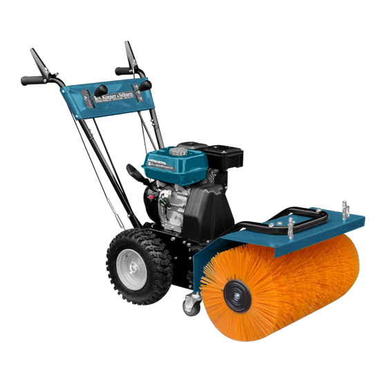
Page 5: Main Components
MAIN COMPONENTS 1. Chassis Fig. 1 2. Damper 3. Fuel tank 4. Control handle 5. Control panel 6. Brush protector 7. Brush 8. Casters 9. Wheel 10. Attachment fasteners 11. Engine SCOPE OF SUPPLY A – Handle with pre-installed rods 1 pcs Fig. - Page 6 ASSEMBLY You may need an assistant during assembly. PLEASE NOTE! MOUNTING THE FRONT MOUNTING THE FRONT AND BRUSH CONTROL CABLES AND BRUSH CONTROL CABLES Attach the cable eyelet to the corresponding hole (fig. 3). Fig. 3 The cables are supplied pre-wired to the control panel. PLEASE NOTE! MOUNTING THE CONTROL HANDLE MOUNTING THE CONTROL HANDLE...
-
Page 7: Device Operation
DEVICE OPERATION The engine is supplied without oil and gasoline. PLEASE NOTE! FILLING OIL FILLING OIL Place the engine in a horizontal position. Remove the oil filler plug and add oil to the very edge of the oil filler (fig. 7). FUEL FUEL Only unleaded gasoline is recommended for the generator. - Page 8 Fig. 10 Fig. 11 Fig. 12 Fig. 13 Fig. 14 Do not release the starter handle abruptly or throw it! While holding the starter handle, slowly allow the rope PLEASE NOTE! to return to its initial position. BEFORE GETTING STARTED WITH THE MULTIFUNCTION MACHINE BEFORE GETTING STARTED WITH THE MULTIFUNCTION MACHINE •...
- Page 9 • Always wear appropriate protective clothing such as a long-sleeved button-down shirt, safety goggles or face shield, ear muffs, and a dust mask. • Keep hands, feet, loose clothing, and long hair away from the area of the moving parts. •...
-
Page 10: Operation Tips
Fig. 15 Cleaning with the brush and snow shovel С Before cleaning: 1. Move the brush direction lever (B) to the desired position (see “Brush direction”). А 2. Choose a speed depending on the route and job complexity. 3. Engage the brush drive (C). В... -
Page 11: Stopping The Engine
STOPPING THE ENGINE STOPPING THE ENGINE 1. Move the throttle lever to the idle position and allow the engine to run 12-20 seconds before moving the lever to the “Stop” position. (fig. 20). 2. Set the engine switch to the “OFF” position (fig. 21). Never leave the snow blower unattended with the engine running. -
Page 12: Maintenance And Repair
Fig. 19 Fig. 20 С В С А В А Fig. 21 Fig. 22 В А MAINTENANCE AND REPAIR RECOMMENDED MAINTENANCE SCHEDULE Unit Action Inspection and tightening Check of fasteners Level check Engine oil Replacement Level check Transmission oil Replacement Cleaning Air filter Replacement... -
Page 13: Troubleshooting
Contact your distributor or local representative to have belts replaced. Do not change them yourself. Repair and adjustment of the snow blower must be carried out in a safe place away from traffic and other hazards. Remove spark plug wire before adjusting or servicing. RESIDUAL RISKS RESIDUAL RISKS All residual risks cannot be avoided even if the machine is used according to the instructions. -
Page 14: Terms And Conditions
WARRANTY SERVICE TERMS TERMS AND CONDITIONS: TERMS AND CONDITIONS: The international manufacturer warranty is 1 year. The warranty period starts from the date of purchase. In cases when warranty period is longer than 1 year according to local legislation please contact your local dealer. - Page 16 CONTACTS Deutschland: DIMAX International GmbH Deutschland, Hauptstr. 134, 51143 Köln, www.ks-power.de info@dimaxgroup.de Polska: DIMAX International Poland Sp.z o.o. Polen, Warczawska, 306B 05-082 Stare Babice, www.ks-power.pl info.pl@dimaxgroup.de Україна: ТОВ «Техно Трейд КС», вул. Електротехнічна 47, 02222, м. Київ, Україна www.ks-power.com.ua sales@ks-power.com.ua...
Need help?
Do you have a question about the KS 7HP-MFM 60 and is the answer not in the manual?
Questions and answers