
Summary of Contents for Austin Hughes InfraSolution X Series
- Page 1 Smartcard Access Control for Racks User Manual XMS-02-S, InfraBox GUI & SNMP X-2000 X-1000 X-800 Smartcard Handle Designed and manufactured by Austin Hughes UM-X-800-XMS-02-S-Q420V1 www.austin-hughes.com...
- Page 2 Legal Information First English printing, November 2020 Information in this document has been carefully checked for accuracy; however, no guarantee is given to the correctness of the contents. The information in this document is subject to change without notice. We are not liable for any injury or loss that results from the use of this equipment.
- Page 3 Before Installation ■ It is very important to locate the equipment in a suitable environment. ■ The surface for placing and fi xing the equipment should be stable and level or mounted into a suitable cabinet. ■ Make sure the place has good ventilation, is out of direct sunlight, away from sources of excessive dust, dirt, heat, water, moisture and vibration.
-
Page 4: Table Of Contents
Contents < Part. 1 > Hardware Tips for Hardware Package Contents InfraBox X-1000 / X-2000 Handle X-800P / X-800M Door Sensor Installation ( Inductive / IR / Mechanical ) P.19 < Part. 2 > P.26 < Part. 3 > Environmental Sensor & Peripherals Temp. - Page 5 Intentionally Left Blank UM-X-800-XMS-02-S-Q420V1 www.austin-hughes.com...
-
Page 6: Part. 1 > Hardware 1.1 Tips For Hardware
< Part 1 > Hardware < 1.1 > Tips for hardware Prepare a notebook computer Start To install IP setup utilities Confi gure IP setting For each InfraBox ONE by ONE InfraBox installation Place the rackmount box on the top rear side of the cabinet Smartcard handle installation For front &... -
Page 7: Package Contents
< 1.2 > Package Contents Unpacking The equipment comes with the standard parts shown on the package contents. Check and make sure they are included and in good condition. If anything is missing, or damage, contact the supplier immediately. X-2000 - X-2000 X-1000 InfraBox, 1 pc - 800 MiFARE... -
Page 8: Infrabox X-1000 / X-2000
< 1.3 > InfraBox X-1000 / X-2000 X-1000 X-2000 Power input Temp. LED display x 2 Dual power input ( option ) Smoke / Shock sensor port x 2 Door cable DB-9 connector x 2 LED Light Bar port x 2 Connect to the front and rear handle Port for 3rd party alarm board x 1 “Act in Out”... - Page 9 < 1.3 > InfraBox X-1000 / X-2000 Key hardware Installation Diagram - InfraBox / Handle / Door Sensor Rear Door Front Door InfraBox SmartCard handle Door sensor with 6’ cable Door cable ( door section ) Door cable ( cabinet section ) InfraBox Daisy Chain Connection InfraBox X-2000 InfraBox X-1000...
- Page 10 < 1.3 > InfraBox X-1000 / X-2000 Installation Diagram - PDU / Fan / Sensor / Peripheral Front Door Rear Door Item Qty. Location LED Light Bar front & rear top inside Smoke Sensor rear inside top Flashing LED Beacon front cabinet roof Temp.
- Page 11 < 1.3 > InfraBox X-1000 / X-2000 IP Setup for InfraBox Before place the InfraBox to the cabinet, user MUST confi gure the IP setting for the InfraBox. It takes around 1-2 minutes to complete : 1. Prepare a notebook computer to download the IP setup utilities from the link below : http://www.austin-hughes.com/support/utilities/infrasolutionX/InfraBoxSetup.msi 2.
- Page 12 < 1.3 > InfraBox X-1000 / X-2000 IP Setup for InfraBox 5. Click “ Scan “ to search the connected InfraBox. 6. Change the IP address / Subnet mask / Gateway, then Click “ Save “ to confi m the setting of InfraBox. The default IP address is as below : IP address: 192.168.0.1...
-
Page 13: Handle X-800P / X-800M
< 1.4 > Handle X-800P / X-800M Universal Mounting Cut-out To achieve the highest level of interoperability off ered in the cabinet industry, the X-800 handle applies the universal mounting cut-out. It avoids costly and complicated door customization for the smartcard handle integration. Unit : mm Cut-out Back View... - Page 14 < 1.4 > Handle X-800P / X-800M Installation for Single Point Lock While insert the screws to secure the handle with electrical power screwdriver, please set the torque NOT exceed 8 kgf/cm Rack door 1. Mount the smartcard handle to the universal mounting position. 2.
- Page 15 Pay attention to the following points when install the lock system. Otherwise, it may cause handle distortion and malfunction. 1. Make sure Cam lock can slide into the hole without stress. The cut-out of the cam hole with enough space tolerance. Cam lock hole Cam lock hole Door...
- Page 16 < 1.4 > Handle X-800P / X-800M Installation for ( light-duty rod-latch ) 2 - point Lock Rod latch Rack door While insert the screws to secure the handle with electrical power screwdriver, please set the torque NOT exceed 8 kgf/cm 1.
- Page 17 Pay attention to the following points when install the lock system. Otherwise, it may cause handle distortion and malfunction. 1. Make sure Two ends of latch rod can entry into the top & bottom holes without stress. The top & bottom holes with enough space tolerance. Lock hole Lock hole 2-point lock holes...
- Page 18 < 1.4 > Handle X-800P / X-800M 2 - point Lock Installation for ( rod control system ) Rod control system >>>>> Orignal handle screws While insert the screws to secure Rack door the handle with electrical power screwdriver, please set the torque NOT exceed 8 kgf/cm 1.
- Page 19 Pay attention to the following points when install the lock system. Otherwise, it may cause handle distortion and malfunction. 1. Make sure Two ends of latch rod can entry into the top & bottom holes without stress. The top & bottom holes with enough space tolerance. Lock hole Lock hole 2-point lock holes...
- Page 20 < 1.4 > Handle X-800P / X-800M Important Note for Key lock Under Smartcard mode, always keep key cylinder to 12 o’clock direction. Sensor area Key lock mode Key cylinder to 9 o’clock direction Under key lock mode, even present the Present the smartcard and smartcard, the handle still keeps locked.
- Page 21 < 1.4 > Handle X-800P / X-800M Maintenance Key ( MK-001 ) Improper key usage may cause the cylinder stuck at abnormal direction 1 to 2 o’ clock. Under this circumstance, the maintenance key (MK-001) is required to solve the problem. Please insert the maintenance key to the cylinder with push force for turning it to normal direction 9 or 12 or 3 o’clock.
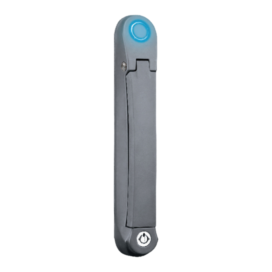
- Page 22 < 1.4 > Handle X-800P / X-800M Handle Operation How to unlock the handle & open the door properly Locked status in Unlocked status in blue green silver white Within 10 seconds after smartcard detection, users should : Flashing Flashing - lift up the handle >>>...
- Page 23 Intentionally Left Blank UM-X-800-XMS-02-S-Q420V1 www.austin-hughes.com...
- Page 24 < 1.5 > Door Sensor - Inductive Sensor Inductive Door Sensor, pair ( S-DSI ) Features Package content light weight Inductive sensor w/ 2m cable x 2 mini size ( 32.5 x 12.2 x 9.2 mm ) 2mm adhesive tape x 6 Mounting bracket x 2 Requirement cabinet frame made of iron...
- Page 25 Suggested Installation steps sensor position - connect to the handle - guide & fi x the cable with cable clips ( bundle with handle package ) - place the sensor at the top of the door, close to the opening side - adjust the sensor with adhesive tape or mounting bracket to ensure the sensing distance between door to frame within 3mm while door in close status...
- Page 26 < 1.5 > Door Sensor - IR Sensor IR Door Sensor, pair ( S-DIR ) Features Magnetic base for easy setup No custom cutting required on doors Light weight & mini size ( 33 x 19 x 7 mm ) 2m cord Requirement rack frame made of ferrous metal ( iron )
- Page 27 Suggested Installation steps sensor position - connect to the handle - guide & fi x the cable with cable clips ( bundle with handle package ) - place the sensor at the top of the door, close to the hinge side - adjust the sensor to ensure the sensing distance between door to frame within 5mm while door in close status - stick the refl...
- Page 28 < 1.5 > Door Sensor - Mechanical Mechanical Door Sensor, pair ( S-DSW ) Package content Low cost / precise Mechanical sensor w/ 2m cable x 2 Size ( 36.3 x 15 x 30.75 mm ) Mounting bracket x 2 2m cord Top View Front View...
- Page 29 Installation steps Suggested - connect to the handle sensor position - place the sensor at the top middle of the door - install the sensor in the custom hole - secure it with bundled mounting screws 6#32x4.5mm x 2 Sensor Operation DOOR CLOSE DOOR OPEN - close door...
- Page 30 < 1.5 > Door Sensor Specifi cation Inductive Door Sensor Mechanical Door Sensor Part no. S-DSI S-DSW Sensitivity Actuation 3.00 mm Travelling Distance 9.25 mm Operating Force 3.5±1 N Sensing distance Max. 3mm Sensing object Ferrous metal Power Requirement Voltage 12VDC, powered by sensor port Current Consumption 100mA...
-
Page 31: Part. 2 > Pdu 2.1 Pdu
< Part 2 > < 2.1 > PDU Under an InfraSolution X network, each InfraBox ( X-2000 series ONLY ) supports InfraPower intelligent PDU x 4 in a daisy chain. Each PDU comes with Temp. & Humid. sensor port x 2 W series : monitored PDU WS series : switched PDU WSi series : outlet level measurement switched PDU... -
Page 32: Part 3 > Environmental Sensor & Peripherals
< Part 3 > Environmental Sensor & Peripherals < 3.1 > Temp. & Humidity Sensor Each InfraBox provides Temp. & Humid. Sensor port x 2. If more TH sensors required, two temp. & humid. sensor ports on each integrated PDU can be applied. Temp. -
Page 33: Smoke Sensor
< 3.2 > Smoke Sensor Smoke sensor comes with a RED LED. When smoke alarm triggers, the RED LED lights on with beep sound continuously. Smoke Sensor Part no. IG-S01-1M Sensitivity Smoke sensitivity 0.15 ~ 0.3 dB/m Alarm Output Solid State Relay 24VDC@1A Alarm LED Audio Alarm... -
Page 34: Shock Sensor
< 3.3 > Shock Sensor Shock sensor comes with a RED LED. When shock alarm triggers, the RED LED lights on continuously. Shock Sensor Part no. IG-V01-1M Sensitivity Detection radius 3.5 m Adjustable sensitivity Internal micro knob with screwdriver cross slot Alarm Output Solid State Relay 12VDC@100mA... -
Page 35: Water Sensor
< 3.4 > Water Sensor Water Sensor Part no. IG-W01-3M Measurement Range Wet or Dry (-20°C to 60°C) Rope Sensor Length Power Requirement Voltage 5VDC, powered by sensor port Power consumption 125 mWatt Connection Extension cable length 3m ( non-detection ) Environmental Operating -20 to 60°C Degree... -
Page 36: Led Light Bar
< 3.5 > LED Light Bar Under InfraSolution X software, the LED light bar can be enabled / disabled / always ON. When the LED light bar is enabled & connected, it will be ON within 10 seconds after the handle lock is released. LED Light Bar Part no. -
Page 37: Led Beacon
< 3.6 > LED Beacon The LED Beacon can be stuck fi rmly by the bundled adhesive tape. LED Beacon Part no. IG-FB03-1M Notifi cation Len Color Blue Light Source White Flash Rate 120 fl ashes per minute Power Requirement Voltage 12VDC, powered by sensor port Current Consumption... -
Page 38: Part. 4 > Xms-02-S Infrabox Gui Software 4.1 Device Monitoring & Setting
< Part 4 > XMS-02-S InfraBox GUI Software < 4.1 > Device Monitoring & Setting Each InfraBox comes with a FREE built-in GUI software ( fi rmware with web GUI & SNMP features ONLY ), XMS-02-S , which allows you, via an I.E. web browser, to see InfraBox’s data and remotely manage the InfraBox over a TCP / IP Ethernet network. - Page 39 < 4.1 > Device Monitoring & Setting In “ PDU Setting “ , you can - Change “ Name “ and “ Location “ of PDU - Change “ Alarm amp. “ , “ Rising alert amp. “ and “ Low alert amp. “ of PDU circuits - Click “...
- Page 40 < 4.1 > Device Monitoring & Setting In “ Outlet Setting “ , you can - Change the “ Name “ of PDU outlet - Change the “ Power up sequence delay “ of PDU outlet ( Switched PDU only ) - Change “...
- Page 41 < 4.1 > Device Monitoring & Setting In < TH details > , you can - Activate / Deactivate the TH sensors of PDU - Change “ Location “ of TH sensors of PDU - Change “ Alarm Setting “ & “ R. Alert Setting “ of TH sensors of PDU - Click “...
- Page 42 < 4.1 > Device Monitoring & Setting In < Access Control > , you can - View the handle model - View & edit the < Rack ID > & < Zone > - Click “ Apply “ to fi nish UM-X-800-XMS-02-S-Q420V1 P.37 www.austin-hughes.com...
- Page 43 < 4.1 > Device Monitoring & Setting In < Door > , you can view - The door status - The door last opened time - The door last closed time - The duration of the door being opened In < Card Access > , you can view - The last smartcard no.
- Page 44 < 4.1 > Device Monitoring & Setting In < Card Assignment> , you can assign, edit or delete user card Card Assignment (1) Direct input the last 8 digits of the card number to the fi eld Card Edition (1) Direct change the existing card numbers in the fi eld Card delete (1) Direct remove the existing card numbers from the fi...
- Page 45 < 4.1 > Device Monitoring & Setting Export & Import Handle Confi guration In < Export > and < Import >, it provides a quick way to confi gure other handles with same or similar confi guration on < Card Assignment >. Steps for Export : 1.
- Page 46 < 4.1 > Device Monitoring & Setting In < Setup >, you can - Enable / disable T / TH sensor, Smoke / Shock sensor & PDU - Change “ Alarm Level “ of T / TH sensor - Change Lamp to “ Disable “ , “ Always ON “ or “ Turn on when door open “ - Click “...
-
Page 47: System Setting
< 4.1 > Device Monitoring & Setting In < Audio and Visual Output Setting >, you can - Enable / Disable the “ Buzzer “, “ Beacon “ & “ Alarm out “ output when the sensor event is triggered <... - Page 48 < 4.2 > System Setting In < Login >, you can - Change the “ Login name “ of the WEB GUI - Change the “ Password “ of the WEB GUI - Enter the password in “ Confi rm password “ & Click “ Apply “ to fi nish In <...
-
Page 49: Snmp
< 4.3 > SNMP Managerment The InfraBox can manage the connected devices ( handles, sensors & PDU up to 4 levels ) via SNMP v2c ( Simple Network Management Protocol ) InfraBox X-1000 series ONLY manages handles via SNMP You can download the SNMP MIB fi le from the link below: http://www.austin-hughes.com/support/utilities/infrasolutionX/X-2000.zip ( X-2000 series ) http://www.austin-hughes.com/support/utilities/infrasolutionX/X-1000.zip ( X-1000 series ) To enable the SNMP support, please take the following steps. - Page 50 < 4.3 > SNMP Managerment 6. The SNMP settings window appears as below 7. Click “ Enable “ in “ SNMP agent “ to start the SNMP agent service 8. Input “ Read community “. Default is “ public “ 9.
- Page 51 Intentionally Left Blank UM-X-800-XMS-02-S-Q420V1 www.austin-hughes.com...
- Page 52 The company reserves the right to modify product specifi cations without prior notice and assumes no responsibility for any error which may appear in this publication. All brand names, logo and registered trademarks are properties of their respective owners. Copyright 2020 Austin Hughes Electronics Ltd. All rights reserved. UM-X-800-XMS-02-S-Q420V1 www.austin-hughes.com...
Need help?
Do you have a question about the InfraSolution X Series and is the answer not in the manual?
Questions and answers