Table of Contents
Advertisement
Quick Links
Advertisement
Table of Contents

Summary of Contents for APE Flex Boost
- Page 1 Programmable Boost Controller ALTERNATIVE PERFORMANCE ENGINEERING, LLC...
-
Page 3: Table Of Contents
What’s Included ................6 Module Passkey ................7 Installation ....................8 Flex Sensor Installation ..............8 Flex Boost Solenoid Connections ............. 8 Wiring Harness ................10 Wiring Harness Connections ............11 Gauge 1 & 2 Installation ..............12 iOS / Android App .................. 13 Flex Boost Features ................ -
Page 5: Introduction
The Alternative Performance Engineering Flex Boost is an advanced electrnoic boost controller, ethanol gauge and generic Bluetooth gauge all in one. Flex Boost combines all of the features of our Flex Boost product with the addition of a programmable boost controller. Boost can be configured based on Ethanol content or RPM and if you add a manifold pressure sensor you can configure an Over-Boost Fail safe. -
Page 6: Getting Started
• The Flex Boost cannot be used with external waste gates that are in a poor, worn or non-serviceable condition. •... -
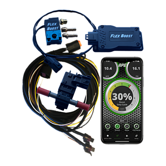
Page 7: What's Included
Check to make sure you have all of the necessary components in your kit: • Flex Boost Module • Wiring Harness • Flex Boost Solenoid and fittings • Flex Fuel Sensor (optional) • Quick Connect Fuel Fittings and hose clamps •... -
Page 8: Module Passkey
Module Passkey On the back of the Flex Boost Module there is a sticker that looks like this. This indicates the Serial Number (SN) and the Passkey (PK) that is used by the IOS or Android app to allow the user to alter any of the default configuration parameters of the device. -
Page 9: Installation
1) Install Flex Fuel Sensor anywhere in the fuel lines. A good place is at the fuel filter. Make sure the Flex Fuel Sensor connector on the Flex Boost wiring harness is able to reach the sensor. 2) You can use the supplied fuel line adapters to connect the Flex Fuel sensor to the fuel filter. - Page 10 Flex Boost Solenoid Connections Internal/Single Port Wastegate Connections Port 1: Brass Muffler Port 2: Wastegate Port 3: Manifold/Turbo Pressure OOST This configuration will give the highest boost when the duty cycle is over 90% and the minimum boost will be set by the wastegate spring.
-
Page 11: Wiring Harness
Wiring Harness Below is the definition for each of the connectors on the supplied wiring harness. Flex Boost Module Connection White Wire: DC Output (0-5V) Purple Wire: E85 Raw Sensor Output (integrated Pull-Up Resistor) Brown Wire: Tach Input Yellow Wire: Switched... -
Page 12: Wiring Harness Connections
Purple Wire: Raw ethanol sensor output that can be sent to an ECU Brown Wire: Can input a tach signal or even a port injection fuel injection signal to let the Flex Boost calculate ROM Yellow Wire: Connect to a Switched 12V input power source... -
Page 13: Gauge 1 & 2 Installation
2) Plug the Flex Boost Module into the harness and mount in your car. 3) Now it is time to start up the APE app on your phone. 4) Use the sensor manufacturers specifications to configure Gauge 1 & 2 in the settings tab. -
Page 14: Ios / Android App
Play Store. Open the app and connect to your device, you should see your serial number listed as something like “APE-FB-10001”. Select your device and hit “Connect” to get to the main dashboard of the app. The app may ask... -
Page 15: Flex Boost Features
Flex Boost Features Ethanol and Fuel Temperature Gauges The Main dashboard screen displays the Ethanol content and fuel temperature as read from the ethanol content sensor. It also has two mini gauges that are used to display the two 0V-5V inputs. -
Page 16: Dc Gauges
DC Gauges Selecting either Gauge 1 or 2 in the top corners will swap that gauge into the center and put the Ethanol Content in the corner. The scaling and visual appearance of the gauges can be configured in the settings tab. If you set the warning range in the settings tab and your gauge hits that range, the gauge will turn red. -
Page 17: Landscape Mode
Landscape mode If you are on the dashboard screen and rotate your phone counter- clockwise, then you the gauges will rotate to a landscape view. If you are on the dashboard screen and rotate your phone clockwise, then you will be taken to the data-logging screen. -
Page 18: Data-Logging Screen
Data-Logging Screen Rotating your device to the right will show the data logging screen. You can only get to the datat logging screen from the main dashboard, so if you are on the boost controller tab and want to see datalogging, you have to go back to the main dashboard tab and then rotate your phone clockwise. -
Page 19: Boost Controller Screen
Boost Controller Screen The Boost Controller screen shows you both of the DC gauge inputs and it shows you the current duty cycle being sent to the Flex Boost Solenoid. Current value read Current value read by Gauge 1 input. -
Page 20: Boost Profile Editing
Boost Profile Editing You can have up to four profiles, and they are completely customizable. See description of all of the settings below. The Flex Boost allows the user to set up the boost controller duty cycle for two different ethanol settings. -
Page 21: Rpm Based Boost Control
RPM Based Boost Control You can raise or lower the Boost Controller duty cycle across four separate configurable RPM bands. You must have the Tach input enabled and configured correctly for this to work. We recommend setting a RPM range below idle, and then setting it to -100% in order to keep the Flex Boost solenoid from clicking when the engine is not running. -
Page 22: Over-Boost Safety
Over-Boost Safety The Flex Boost has the abilityh to configure one of the DC gauge inputs for Over-Boost Safety. You must first configure your Gauge settings and then you can select that gauge in the Over-Boost Safety drop down in the settings tab. -
Page 23: Fuel Calculator Screen
Fuel Calculator Screen The fuel calculator can show you how to mix Ethanol with Gasoline to achieve a desired Ethanol mixture, for example E65. You can use the datalogging screen to help determine if you need to lower your Ethanol mixture. -
Page 24: Settings Screen
This determines which value is output on the Pass Key not used for White wire. E85 (E0 = 0V, E85=5V), Flex Boost Gauge 1 or Gauge 2 Display Name is what Can turn off Gauge is shown when Gauge Display on dashboard is in the Center. -
Page 25: Dc Voltage Output
5V = E85 content. Note: The DC Out signal has a weak drive strength, if feeding into an ECU with a pullup resistor, the Flex Boost may not be able to drive this signal all the way to ground. In this event, calibrate your low voltage point accordingly in your ECU. -
Page 26: Gauge Customization
Gauge Customization You can change the end points in the color bar to change the upper and lower limits shown on the gauge. This can be useful if you have a sensor that displays a much higher range than what is needed for your application. -
Page 28: Warranty
Returns If you are experiencing an issue with your Flex Boost module, please contact us so we can help resolve it. If you wish to return the system, all components must be returned in original packaging, in resalable condition.
Need help?
Do you have a question about the Flex Boost and is the answer not in the manual?
Questions and answers