Table of Contents
Advertisement
Quick Links
OPERATION MANUAL
AIR LEAK TESTER
MODEL LS-1866
No. LS-1866-941B1-H
1 INTRODUCTION
2 GENERAL INFORMATION
AND SPECIFICATIONS
3 LEAK TESTING OVERVIEW
4 FEATURE SUMMARIES
5 INSTALLATION
6 PARTS IDENTIFICATION
AND FUNCTIONS
7 BASIC OPERATIONS
8 COMPENSATION MODE
(MASTER-PRESET)
9 CALIBRATION (CAL) MODE
10 ORIGINAL (ORG) MODE
11 INTERFACE
12 MAINTENANCE AND
TROUBLESHOOTING
13 APPENDIX
Advertisement
Table of Contents
Troubleshooting

Subscribe to Our Youtube Channel
Related Manuals for Cosmo LS-1866

Summary of Contents for Cosmo LS-1866
- Page 1 1 INTRODUCTION 2 GENERAL INFORMATION OPERATION MANUAL AND SPECIFICATIONS AIR LEAK TESTER 3 LEAK TESTING OVERVIEW MODEL LS-1866 4 FEATURE SUMMARIES No. LS-1866-941B1-H 5 INSTALLATION 6 PARTS IDENTIFICATION AND FUNCTIONS 7 BASIC OPERATIONS 8 COMPENSATION MODE (MASTER-PRESET) 9 CALIBRATION (CAL) MODE...
-
Page 3: Table Of Contents
TABLE OF CONTENTS TABLE OF CONTENTS INTRODUCTION ........................... 5 Introduction ............................... 5 Safety Hints .............................. 5 Notes ................................ 6 GENERAL INFORMATION AND SPECIFICATIONS ..............7 General Information ..........................7 Features ..............................7 Specifications ............................9 2.3.1 General Specifications ........................9 2.3.2 Test Pressure Gauge ........................ - Page 4 TABLE OF CONTENTS Names of Test Pressure Gauge Components (Low · Medium / Vacuum Pressure) ......40 7.4.1 Output Mode ..........................40 7.4.2 Setting test pressure limits ......................41 7.4.3 Locking the key of the test pressure gauge ................... 42 7.4.4 Zero reset of the test pressure gauge ....................
- Page 5 3 APPENDIX ..........................87 13.1 EXTERNAL APPEARANCE ........................87 13.2 PNEUMATIC CIRCUIT ........................... 88 13.2.1 INTELLIGENT I AIR CIRCUIT LS-1866 ..................88 13.3 Pressure Unit Conversion Table ......................89 13.4 Flow Unit Conversion Table ........................89 13.5 CE Marking ............................. 89 13.6...
-
Page 7: Introduction
1 INTRODUCTION INTRODUCTION Thank you very much for purchasing COSMO’s LS-1866 Air Leak Tester. This operation manual provides information about the LS-1866 Air Leak Tester, including its functionality, operating instructions, and precautions in handling. Before using the product, read this manual carefully to assure proper handling. After reading, keep the manual in a safe place for reference. -
Page 8: Notes
1 INTRODUCTION CAUTION Do not use the unit in places that are damp, that are Do not disassemble the unit. If disassembled, the unit exposed to direct sunlight or that are outside the could malfunction, resulting in physical harm or temperature range of 5°C to 40°C. -
Page 9: General Information And Specifications
GENERAL INFORMATION AND SPECIFICATIONS LS-1866 is an air leak tester based on a differential pressure method that tests the air tightness of various parts and products. Air leak tester allows not only enhancing a detection capability but also an automated detection process. - Page 10 2 GENERAL INFORMATION AND SPECIFICATIONS Quick mounting brackets • Tester can be removed from the machine easily from the front side by using these brackets. Clamp signal • This tester can control external solenoid valve to drive air cylinder. Use of this feature allows building a simple and low cost machine system.
-
Page 11: General Specifications
2 GENERAL INFORMATION AND SPECIFICATIONS 2.3.1 General Specifications Minimum reading Standard: 0.1 Pa Display range (Guaranteed) Standard: ±999 Pa Sensor range Standard: ±2000 Pa Sensor proof pressure 5 MPa Reading accuracy *1 ±2.5% of rdg ±1Pa for range above 50Pa, ±2Pa for 0-50Pa range (within guaranteed accuracy range) Leak rate reading range 0.00 to ±999mL/min (floating point) -
Page 12: Timer Setting
Be sure that those limits are within the range. 2.3.5 Model Classifications NOTE The maximum working pressure for the vacuum pressure model LS-1866 A B - C (V) is also constrained by atmospheric pressure conditions. Intelligent I Pneumatic Circuit Pneumatic... -
Page 13: Leak Testing Overview
3 LEAK TESTING OVERVIEW LEAK TESTING OVERVIEW After a tested part is charged with an air pressure, the resulting change in its internal pressure is measured to detect a leak. A non-leaking reference part (master) is made available and is charged with a pressure concurrently with the tested part in Leak Testing. -
Page 14: Internal Pressure Changes Of The Tested Part And Master
3 LEAK TESTING OVERVIEW 3.1.2 Internal pressure changes of the tested part and master In the BAL and the DET stage, the differential pressure resulting from leaks rises at a constant rate with time. In the DET stage, the differential pressure sensor (DPS) output is zeroed through an auto-zero operation before a differential pressure reading is produced. - Page 15 Equivalent internal volume [mL] Detection time The LS-1866 uses the above equation for the calculation of the leak rate. Note that the tester uses standard atmospheric pressure for this calculation. If the tested part is tested under standard pressure, 1.013 × 10 Pa, and standard temperature, 20°C, then the tester displays a standard volume per time.
-
Page 16: Estimating The Test Timer
3 LEAK TESTING OVERVIEW Required measurement timer increases under the following conditions: • Test pressure is rather high. • Internal volume of the tested part is large. • Surface area of the tested part is small • Leak specification is small. •... -
Page 17: Feature Summaries
4 FEATURE SUMMARIES FEATURE SUMMARIES 4.1.1 Theory of Master-Preset The measured pressure change in a leak test typically contains both the true leakage and drift errors due to adiabatic compression and change in the ambient temperature. The pressure change due to leak remains consistent over time, while the drift errors tend to decrease over time until completely stabilized. -
Page 18: When To Execute A Master-Preset Process
4 FEATURE SUMMARIES 4.1.3 When to execute a Master-Preset process Master-Preset process is recommended under one of the following conditions: Production part changeover For production lines that produce multiple part models, each model should be assigned to a specific leak tester channel. Therefore, a Master-Preset process is required on the new channel immediately after the model changeover. -
Page 19: Two-Level Limit Setting And Noise Reduction (Nr) Mode
4 FEATURE SUMMARIES Two-level limit setting This leak tester permits setting a small leak limit (Hi-NG) and a large leak large leak limit (HH-NG) in the DET stage. In the normal leak test cycle, nonconforming parts can be screened out according to the amount of leakage. -
Page 20: Sensor Protection
4 FEATURE SUMMARIES If the tested part contains water or an oil, or if the leak tester is used along with water-immersion test, water and/or oil may enter the tester from the tested part during exhaust stage causing malfunctioning. The feature protects sensor from such contamination 4.5.1 Cleaning pneumatic circuit by Exhaust air blow (DL3) Air blow of DL3 is used to clean the pneumatic circuit and prevent DPS from contaminated by blowing off... -
Page 21: Clamp Output
4 FEATURE SUMMARIES While the leak tester is running and during master preset sampling, 24 VDC is generated from the 2P connector on the leak tester rear panel. This output can be used to drive an external clamp cylinder solenoid valve. -
Page 23: Installation
Damage to the hardware or physical injury can result. 5.1.1 Using Quick Mounting Brackets (standard) The LS-1866 comes with mounting brackets that can be attached or detached with two front-panel screws. Use of these mounting brackets allows for better space utilization for installing testers side by side by removing the need to insert a screwdriver along the side of each tester. - Page 24 Place an LS-1866 fitted with mounting brackets A and B somewhat in front of the intended site of installation. • Push the LS-1866 backward to force the tip of the mounting bracket B into the square holes in the mounting base. •...
-
Page 25: Electrical Connection
5 INSTALLATION CAUTION Electrical Shock Hazard Turn off the main power before connection. Connecting power This tester can accept 100 to 240 VAC ±10% at 50/50 Hz single-phased power supply. Make sure to properly connect the ground. The standard power cord supplied with the leak tester is rated 100 to 125 VAC. -
Page 26: Pneumatic Connection
5 INSTALLATION CAUTION Shut off the pressure source before connecting or disconnecting it. 5.3.1 Connection ports Connect a test pressure source to the oil mist separator IN port: Rc1/4. A high test pressure source must be connected to the air filter. Connect a pilot pressure source to the filter IN port: 6mm one-touch joint. -
Page 27: Notes On Source Air
5 INSTALLATION 5.3.3 Notes on source air Air that is supplied from a pressure source must be clean and dry. Water or oils penetrating inside of the leak tester may cause the DP sensor to fail. • Symptoms of a differential pressure sensor failure caused by water and oil. Water or oil present in the source air may result in a significant drift of the DPS offset to produce an offset error or large leak failure, requiring repairs by the manufacturer. - Page 28 5 INSTALLATION Use of O-ring If there is an air space that isn’t pressurized at the side of the O-ring, the O-ring will move and causes a pressure drop. If O-ring groove is so tight, the fixture cannot touch the metal surface of the tested part, which results in damage to the O-ring or erratic reading due to spongy fixturing.
-
Page 29: Master Installation
Various Master Chambers are available depending on the internal volume of the tested part. If Master-Preset compensation is used, Cosmo recommends MC-F02A (200c) that is excellent in thermal stability and compatible with broad range of internal volume from small to large. -
Page 30: Choosing Proper Connection To The Tested Part And The Master
5 INSTALLATION 5.4.3 Choosing proper connection to the tested part and the master Recommended nylon tubing types • Use of rigid nylon tubing that is less liable to expansion from pressure is recommended. • Select a tubing type to suit the volume of the tested part and the test pressure. See the table below for general guidelines. -
Page 31: Leak Tester Installation Environment
5 INSTALLATION Location of Leak tester to Avoid Temperature Fluctuation Avoid direct sunlight 1). Avoid direct wind due to doors opening and closing 2) or heating and cooling vents 3). When above cannot be avoided, use a curtain or screen. However, it is not good to cover the whole test stand area completely because of temperature fluctuations that could occur in the tested part. -
Page 32: Procedure For Installation And Adjustment
5 INSTALLATION Preparations: Prerequisites and precautions • Install the tester as instructed in 5, → "Installation," and 11, → "Interfaces." For adjustment, see Section 6.1.4, → "Leak Test Stages." Connect a pressure source that does not have pressure fluctuations and that has a sufficient flow capacity for the test. If 1 Test pressure source 5.3.2 the source pressure fluctuates put another pressure regulator... - Page 33 5 INSTALLATION Master-Preset: Sampling Master-Preset values. NOTE Generally, a time shorter than the test duration determined in Item 4 above is required. Leak tests can be carried out with high measurement accuracy without needing a long test time if leak data is compensated using the Master-Preset feature.
-
Page 35: Parts Identification And Functions
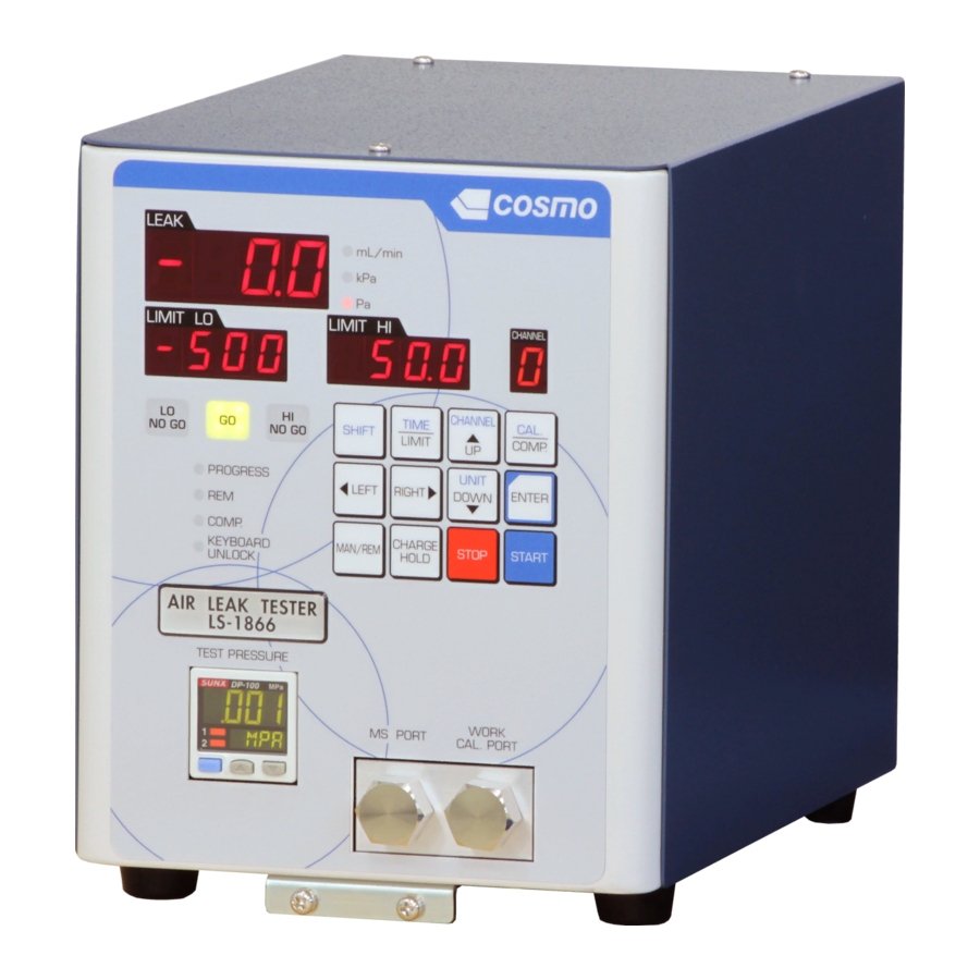
6 PARTS IDENTIFICATION AND FUNCTIONS PARTS IDENTIFICATION AND FUNCTIONS Front Rear Indicators (See Section 6.1.1. → ) Pilot pressure inlet (Connector one-touch joint, filter regulator) Pressure gauge Connect an air pressure regulated through a Provides a digital reading of the test regulator to this port for driving air-operated pressure, and sets and reads test pressure valves. -
Page 36: Indicators
6 PARTS IDENTIFICATION AND FUNCTIONS 6.1.1 Indicators Leak rate indicator Leak rate LO limit indicator MASTER-side limit setting GO LED lamp Acceptance judgement lamp LO NO GO LED lamp Master failure judgement lamp PROGRESS LED lamp Indicates a stage when on or blinking. REM LED lamp On when in remote;... -
Page 37: Keyboard
6 PARTS IDENTIFICATION AND FUNCTIONS 6.1.2 Keyboard TIME/LIMIT key : Used to program or view the stage timers and the limits. (See Sections 7.12 and 7.13. → ) SHIFT key : Enables the function marked in the upper part of each typeface., SFt appears on the leak rate indicator when this key is pressed. -
Page 38: Characters Appearing On The Digital Indicator
6 PARTS IDENTIFICATION AND FUNCTIONS 6.1.3 Characters Appearing on the Digital Indicator Character Symbol Character Symbol Character Symbol... -
Page 39: Leak Test Stages
6 PARTS IDENTIFICATION AND FUNCTIONS 6.1.4 Leak Test Stages Stage Name Symbol Operations • Sealing stabilization wait • Differential pressure offset check Assumes an excessive differential pressure sensor zero point if there is an offset of -300 Pa or less of +300 Pa or more when this stage times out. Charge delay •... -
Page 40: Settings And Led Indications
6 PARTS IDENTIFICATION AND FUNCTIONS Time and limit settings are displayed as stage symbols on the leak rate indicator. Alarms are signaled by either the master failure judgement lamp LO NO GO LED or tested part failure judgement lamp HI NO GO LED blinking together with the stage guidance display to distinguish between a work setting and a tested part setting. -
Page 41: Basic Operations
7 BASIC OPERATIONS BASIC OPERATIONS Turn the power on by pressing the rear-panel power switch. The leak tester starts self-checking its ROM, RAM, and else. It takes about 3 seconds to complete the check. Use the rear panel-mounted regulator to set a test pressure. Adjust the test pressure by turning the knob while observing the front-panel pressure gauge reading. -
Page 42: Names Of Test Pressure Gauge Components (Low · Medium / Vacuum Pressure)
7 BASIC OPERATIONS · · Test Pressure Gauge: Output 1 operation indicator : Lights up when comparative output 1 is ON. Output 2 / analog voltage output operation indicator : Lights up when comparative output 2 is ON. Mode selection key : RUN MODE(This is the pressure detection state) / MENU SETTING MODE / PRO MODE(not use it) Unit display LED display Display of pressure value・output mode・setting value... -
Page 43: Setting Test Pressure Limits
7 BASIC OPERATIONS 7.4.2 Setting test pressure limits The initial setting of the pressure gauge allows programming the common upper and lower limits for all the channels. Setting procedure Pressure limit set mode Upper/lower limit set in RUN mode. Display the setting condition・value in Sub display. -
Page 44: Locking The Key Of The Test Pressure Gauge
7 BASIC OPERATIONS 7.4.3 Locking the key of the test pressure gauge Locking the gauge key prevents the keys from being accidentally pressed while in Measure mode. Key lock set Key lock released 7.4.4 Zero reset of the test pressure gauge Under atmospheric pressure, the reading of the gauge can be reset. -
Page 45: Names Of Test Pressure Gauge Components (High Pressure)
7 BASIC OPERATIONS Test Pressure Gauge LCD display: display the current status of pressure, setting mode, selected indication unit and error code. Operation indicator: Display operation condition of the pressure gauge UP key: Alters the mode or increases ON/OFF set value. DOWN key: Alters the mode or decreases ON/OFF set value. -
Page 46: Setting Test Pressure Limits
7 BASIC OPERATIONS 7.5.2 Setting test pressure limits The initial setting of the pressure gauge allows programming the common upper and lower limits for all the channels. This setting can be altered to programming different limits for even and odd number channel through memory switch selection. -
Page 47: Locking The Key Of The Test Pressure Gauge
7 BASIC OPERATIONS 7.5.3 Locking the key of the test pressure gauge Locking the gauge key prevents the keys from being accidentally pressed while in Measure mode. Keep pressing the key for 5 sec. or longer in measurement mode. The current setting “LoC” or “UnL” is displayed. (Releasing key lock can be done in the same way.) ress the key to select locking or unlocking of the key. -
Page 48: Unlocking The Keyboard
7 BASIC OPERATIONS The leak tester automatically defaults to keyboard lock when turning on the power. Unlock the keyboard to change the settings. To unlock the keyboard Press the ▲UP key and the RIGHT ► key simultaneously for 1 second or longer, and the KEYBOARD UNLOCK LED will light. -
Page 49: Switching Modes
7 BASIC OPERATIONS The leak tester automatically defaults to Measurement mode when turning on the power. To switch to other modes, follow these steps: Press the SHIFT key and the CAL./COMP. key simultaneously to go to Calibration mode. Press the CAL./COMP. key to go to Compensation mode. Press the ENTER key for 1 second or longer go to Original mode. -
Page 50: Viewing Raw Output Of Detected Differential Pressure
7 BASIC OPERATIONS 7.11.2 Viewing raw output of detected differential pressure Press the RIGHT ► key for 1 second or longer while tester is in Measurement mode, and the raw output of detected differential pressure is displayed on the leak rate indicator. This feature is convenient when you want to know the detected differential pressure in case the detected value is displayed in leak rate unit mL/min, or the detected value is compensated. -
Page 51: Limit Setting
7 BASIC OPERATIONS 7.13.1 Viewing During the MASTER-side leak rate limit setting, LO NO GO LED blinks, and during the WORK-side leak rate limit setting, H -NO GO LED blinks. <Operation> Press the TIME/LIMIT key. bAL appears on the leak rate indicator, and the LO NO GO LED blinks, with the setting value appearing on the LO limit indicator. -
Page 52: Unit Selection
7 BASIC OPERATIONS There are two selections available for the unit, the volumetric leak rate, mL/min, or pressure unit, Pa or kPa. The leak unit automatically defaults to Pa or kPa depending on the specifications when turning on the power. NOTE Units can be switched only if the keyboard is unlocked. -
Page 53: Compensation Mode (Master-Preset)
8 COMPENSATION MODE (MASTER-PRESET) COMPENSATION MODE (MASTER-PRESET) Mode to sample Master-Preset values and turn compensation ON and OFF. Master-Preset values can be entered by: • Sampling through keyboard operation (See Section 8.1.2 → ) • Sampling through external signal input automatically in Measurement mode (See Section 8.1.3. -
Page 54: Sampling By Manual Operation
8 COMPENSATION MODE (MASTER-PRESET) 8.1.2 Sampling by manual operation <Operation> Press the START key. The sampling process proceeds in the following sequence: DL1 → CHG → DL2 → BAL(1) → DET(1) → STB → BAL(2) → DET(2) → DL3 → END DET(1) is the DET stage in a normal leak test. -
Page 55: Sampling Externally Through Control I/O Port
8 COMPENSATION MODE (MASTER-PRESET) 8.1.3 Sampling externally through control I/O port <Operation> Press the MAN/REM key in Measurement mode to switch to remote. The MAN LED should light. Turn on the Master-Preset signal. Turn on the Start signal. <Stage> Measurement proceeds in the sequence of the stages: DL1 →... -
Page 57: Calibration (Cal) Mode
9 CALIBRATION (CAL) MODE CALIBRATION (CAL) MODE • Mode to perform leak calibration, DPS calibration, and No-leak tests. • Press the SHIFT key in Measurement mode to display SFt on the leak rate indicator and then press the CAL./COMP. key to enter calibration mode. Each time the RIGHT ► key is pressed, the setup item changes in the following sequence: vE →... -
Page 58: Leak Calibration Using A Leak Master
9 CALIBRATION (CAL) MODE 9.1.3 Leak calibration using a Leak Master Obtain an equivalent internal volume using a Leak Master. <Operation> Connect the Leak Master to the WORK CAL. PORT-side CAL port. Press the SHIFT key to display SFt on the leak rate indicator. Press the CAL./COMP. -
Page 59: Go/No Go Judgement During Leak Calibration
9 CALIBRATION (CAL) MODE CAL then vE will appear on the leak rate indicator, and the calculated equivalent internal volume will be displayed on the leak limit indicator in unit of L. The displayed value will blink. NOTE If the equivalent internal volume is known, the ▲UP and DOWN▼ keys allow manual entry. -
Page 60: Dps Span Inspection
9 CALIBRATION (CAL) MODE CAUTION DPS span calibration is performed by the Cosmo’s representatives. One’s who has been specially trained by Cosmo could also perform it. In such case Cosmo does not guarantee the value after the calibration. 9.3.1 Connecting a Pressure Calibrator This section provides the procedure of the DPS span inspection using the Pressure Calibrator. -
Page 61: Leak Test
9 CALIBRATION (CAL) MODE Initialize the gain coefficient. Pressing the SHIFT and the STOP keys simultaneously for 1 second or longer initializes it to manufacturer’s setting, 1.0. This is a test to verify whether the tester itself is not leaking. The timers for this test is fixed as below CHG timer BAL timer... -
Page 63: Original (Org) Mode
10 ORIGINAL (ORG) MODE ORIGINAL (ORG) MODE Pressing the ENTER key in Measurement mode for 1 second or longer enters Original mode. Original mode consists of the pages listed below. Pressing the RIGHT ► key scroll the pages in the following sequence: P-1 →... -
Page 64: Memory Switch Table
10 ORIGINAL (ORG) MODE 10.2.3 Memory Switch Table No. Setting Function DET stage Judgement timing 1) External stop: b contact pulse External stop: a contact pulse After the tester makes judgement, the judgement signals are held. These signals are cleared by the START, STOP or CHG HOLD signals. The judgement signal is output as pulse. - Page 65 10 ORIGINAL (ORG) MODE Judgement signals are output before an error signal (DL3 stage) to speed up the measurement time. Change the judgement signal to the END stage to avoid the generation of both an acceptance signal and an error signal. The high pressure circuit (H15) verifies the action of the air operated valves by checking the pilot pressure on the basis of pressure switches, not by the air blow (DL3) stage.
- Page 66 10 ORIGINAL (ORG) MODE Serial communication output format Memory switch # Serial communication output format RESERVED Printer format I format T format Selection of Pressurization valve failure detection time・Differential pressure limit Memory switch#23 Time Differential pressure limit 1sec ±100Pa 1sec ±300Pa 1sec ±500Pa...
-
Page 67: Initialization (P-3)
10 ORIGINAL (ORG) MODE Initialization resets all settings to the manufacturer’s settings. <Operation> In the Original mode, press ◄ LEFT or RIGHT ► key several times until P-3 is displayed on the leak rate indicator, and Init is displayed on the HI and LO leak limit indicators. Pressing the ENTER key for 1 second or longer resets all the settings to the manufacturer’s settings. -
Page 68: Noise Reduction (Nr) (P-5)
10 ORIGINAL (ORG) MODE While NR is on, if a measured leak rate exceeds the limit but within the NR limit, NR process starts automatically. In the NR process, the DET stage is iterated a preset number of times. When the tester enters NR process, a timer extension signal is transmitted from external I/O. If the cycle timeout limit program is used by the external controller, use this signal to cancel it. -
Page 69: 1 Interface
12 INTERFACE INTERFACE The control I/O port interfaces the tester to an external device such as PLC with the capabilities to control and receive the test results remotely. This port allows the tester to be integrated into a fully automated line. Connector type: Leak tester side: DB-37P (XM2C-3712-112 OMRON or equivalent) - Page 70 11 INTERFACE Input Photocoupler diode input: 2 groups Input impedance: 3.3 kΩ Input current: 7 mA typ. (24 VDC) Connection method Output Open collector output Load current:100 mA (at 24 VDC). Load when the sum of pins#12 to #18 is 200 mA or less and the sum of pins #31 to #36 is 200 mA or less.
- Page 71 11 INTERFACE Typical PLC connection(NPN) Typical connection with PLC(PNP)
-
Page 72: Channel Selection
11 INTERFACE Channel changes are effected by entering a binary code to pins #21 to 24, pin #21 (CH#3) being the most significant bit (MSB) and pin #24 being the least significant bit (LSB). Channel Channel#3 Channel#2 Channel#1 Channel#0 NOTE Channel 0 (CH0) is selected when Channel#3 to Channel#0 are not selected or all are turned off. -
Page 73: External Signal Timing Charts
11 INTERFACE Leak test start CHANNEL and START signals can be turned OFF while BUSY signal turns ON when the BUSY signal selection is the standard (manufacturer setting). No HH-NG and LL-NG signal will be transmitted unless the leak rate in DET stage exceeds the HH or LL limit. -
Page 74: Serial Communications Interface
This interface port is an asynchronous half duplex serial interface based on EIA-232. This interface provides communication with external devices such as computers (NON-MODEM mode direct connection). Though this port, the LS-1866 transmits leak test data after every test execution and accepts commands from the host. 11.5.1 Interface specifications... - Page 75 11 INTERFACE Name Function Action Wiring Pin # Connected to SD terminal of the RD(RxD) Received data OFF at reception remote equipment. Connected to the RD terminal of SD(TxD) Transmitted data ON at transmission the remote equipment. Connected to the SG terminal of Signal ground the remote equipment.
- Page 76 11 INTERFACE Reading Command Command Function Data unit RLD<CR> Reading test data Leak rate unit RRTO<CR> Reading HH and LL RBHI<CR> Reading BAL_Hi limit (Multi-comparison DT1_Hi) Leak rate unit RBLO<CR> Reading BAL_Lo limit (Multi-comparison DT1_Lo) Leak rate unit RDHI<CR> Reading DET_Hi limit (Multi-comparison DT2_Hi) Leak rate unit RDLO<CR>...
- Page 77 11 INTERFACE Details of commands NOTE “_” represents space (20H). Control commands STT command is effective only during rest stage in measurement mode for remote operation. STP and CHS is effective only in measurement mode for remote operation Response data: ACK or Error •...
- Page 78 11 INTERFACE • HH and LL ratio setting WRTO_VV<CR> Curtailed command Regular command #SS_00_WRTO_VV:GG<CR> Data field Symbol Data type Unit Min. Max. Remarks Identification No. 2 digit integer Command WRTO ASCII code Data 2 digit integer Can be set every 10% from 10 to 90%. Data from “#”...
-
Page 79: Output Formats
Tester is not in a state to execute the command. Checksum error Checksum data does not agree. Ineffective command Command is inappropriate. • Transmitted data from LS-1866 by RLD command (Output format is same as T format.) #SS_00_J_±VV.VV:GG<CR> Data field Data type Unit Min. -
Page 80: Data Format
11 INTERFACE Output format selection By the setting of memory SW_#19 and 20, the format of data output can be selected. RS-232C output format T format I format Printer format • T format: Default format. Only measured leak rates are output in fixed-length. •... - Page 81 11 INTERFACE P format (serial printer output) When an inspection ends, the inspection result is printed in the END stage. TOTAL LEAKGE RESULT [Pa ] [Pa ] [Pa ] GOOD 0003 +0108 +079.0 +029.0 Channel number Judgement Total (Data #) GOOD : Go BAT! : Battery error DPS raw output...
-
Page 82: Checksum
11 INTERFACE 11.5.4 Checksum Checksum is two’s complement of the value that adds every ASCII code in the calculation range. Calculation example: T format Character number Transmitted data ASCII 20 2D 30 30 2E 34 3A Code Lower two digits Note notation notation... -
Page 83: 2 Maintenance And Troubleshooting
12 MAINTENANCE AND TROUBLESHOOTING MAINTENANCE AND TROUBLESHOOTING Periodic inspections help maintain test accuracy and prevent failures. Please perform inspections described in this chapter. Turn on the power of the tester at least 5 minutes before inspection for a warm-up. Check the oil mist separators and filter (Start-up check). Drain any accumulated water and wash the filter if dirty or dusty. -
Page 84: Error Messages
Water, oils, or other zero point tends to shift or lack of repeatability, DPS may be contamination in DPS contaminated. Have a Cosmo representative replace DPS. Detected in DL1 stage. Test pressure may be out of range of the pressure switch. -
Page 85: Improper Test Pressure
12 MAINTENANCE AND TROUBLESHOOTING 12.4.3 E-4 Improper test pressure When arranging a pressure switch to WORK-side measurement system and not using the original one, E-4 error message might be appeared. In that case, the wrong setting of the test pressure or malfunction of the air-operated valve could be its cause. -
Page 86: Leak Test Troubleshooting
12 MAINTENANCE AND TROUBLESHOOTING 12.5.1 When No-Go judgments occur consecutively No-Go judgement Probable cause Treatment Internal mold cavity of the Perform charge hold applying soap tested part. solution on the sealing, and or Leaks from sealing caused by water-immersion test. machining defects Tested part Volume change caused by... -
Page 87: Locating Leaks In Places Other Than The Leak Tester
12 MAINTENANCE AND TROUBLESHOOTING Press the CHG HOLD key to pressurize the tested part and locate leaks applying soap solution. (See Section7.15 → ) NOTE Do not apply soap solution to a vacuum pressure type tester. Disconnect the tubing and fixture from the WORK-side port and apply regulated micro-low pressure and soap solution to locate the leak. -
Page 89: 3 Appendix
13 APPENDIX APPENDIX... -
Page 90: Pneumatic Circuit
13 APPENDIX 13.2.1 INTELLIGENT I AIR CIRCUIT LS-1866 Pneumatic circuit diagram, low pressure model (L), medium pressure model (M) Pneumatic circuit diagram, vacuum pressure model (V) -
Page 91: Pressure Unit Conversion Table
CE marking is affixed to the CE conformed model of LS-1866. Scope of CE marking conformity is the body of LS-1866. For the power cord supplied with the LS-1866 is as the follows: Power cord rated for 100 to 125 VAC is not conformed. -
Page 92: Information To Users (Fcc Rules)
13 APPENDIX Changes or modifications not expressly approved by Cosmo could void the user’s authority to operate the equipment. (excluding particular specifications) This equipment has been tested and found to comply with the limits for Class A digital device, pursuant to part 15 of the FCC Rules. - Page 93 +86-(0)27-8488-5768 +86-(0)27-8488-9768 Wuhan Office Phone: +82-(0)32-623-6961 Korea Cosmo Korea Fax: +82-(0)32-623-6963 Incheon, Korea Phone: +886-(0)2-2707-3131 Taiwan Taiwan Cosmo Instruments Co., Ltd Fax: +886-(0)2-2701-9541 Taipei Office (Head Office) Phone: +886-(0)4-2270-2286 Taichung Office Fax: +886-(0)4-2270-2267 Phone: +60-(0)3-51626677, +60-(0)3-51627766 Malaysia Cosmowave Sdn. Bhd.
- Page 94 * The specifications are subject to change without notice. http://www.cosmo-k.co.jp/ COSMO INSTRUMENTS CO., LTD. 2974-23 Ishikawa, Hachioji, Tokyo 192-0032 Japan Phone: +81-(0)42-642-1357 Fax: +81-(0)42-646-2439...
Need help?
Do you have a question about the LS-1866 and is the answer not in the manual?
Questions and answers
how can i be able to change the number of decimal places from 1 to 2 displayed on the tester limit setting and reading ?