Table of Contents
Advertisement
Quick Links
INSTALLATION INSTRUCTIONS
INSTALLATION INSTRUCTIONS
RHCL: COMMERCIAL AIR HANDLER WITH VARIABLE
(-)HGG COMMERCIAL AIR HANDLERS
FREQUENCY DRIVE (VFD)
NOMINAL 7.5 THROUGH 20 TON AIR CONDITIONING
R-410A REFRIGERANT
2-STAGE AIR-FLOW
Accredited by the RvA
ISO 9001:2008
Certificate Number: 30164
!
!
PLEASE READ CAREFULLY AND KEEP IN A
SAFE PLACE FOR FUTURE REFERENCE.
DO NOT DESTROY
PLEASE READ CAREFULLY AND KEEP IN A
WARNING
!
SAFE PLACE FOR FUTURE
THESE INSTRUCTIONS ARE INTENDED AS AN AID TO QUALIFIE
LICENSED SERVICE PERSONNEL FOR PROPER INSTALLATIO
WARNING
ADJUSTMENT AND OPERATION OF THIS UNIT. READ THES
!
INSTRUCTIONS THOROUGHLY BEFORE ATTEMPTING INSTALL
THESE INSTRUCTIONS ARE INTENDED AS AN AID TO QUALIFIED,
TION OR OPERATION. FAILURE TO FOLLOW THESE INSTRUCTION
LICENSED SERVICE PERSONNEL FOR PORPER INSTALLATION,
MAY RESULT IN IMPROPER INSTALLATION, ADJUSTMENT, SE
A D J U S T M E N T A N D O P E R A T I O N O F T H I S U N I T . R E A D T H E S E
VICE OR MAINTENANCE POSSIBLY RESULTING IN FIRE, ELECTR
INSTRUCTIONS THOROUGHLY BEFORE ATTEMPTING INSTALLA-
CAL SHOCK, PROPERTY DAMAGE, PERSONAL INJURY OR DEATH
TION OR OPERATION. FAILURE TO FOLLOW THESE INSTRUCTIONS
MAY RESULT IN IMPROPER INSTALLATION, ADJUSTMENT, SER-
VICE OR MAINTEMANCE POSSIBLY RESULTING IN FIRE, ELECTRI-
CAL SHOCK, PROPERTY DAMAGE, PERSONAL INJURY OR DEATH.
DO NOT DESTROY
REFERENCE.
SUPERSEDES 92-42673-
92-106595-02-00
Advertisement
Table of Contents

Summary of Contents for ClimateMaster HCLA2090CAR
- Page 1 INSTALLATION INSTRUCTIONS INSTALLATION INSTRUCTIONS RHCL: COMMERCIAL AIR HANDLER WITH VARIABLE (-)HGG COMMERCIAL AIR HANDLERS FREQUENCY DRIVE (VFD) NOMINAL 7.5 THROUGH 20 TON AIR CONDITIONING R-410A REFRIGERANT 2-STAGE AIR-FLOW DO NOT DESTROY PLEASE READ CAREFULLY AND KEEP IN A SAFE PLACE FOR FUTURE REFERENCE. DO NOT DESTROY PLEASE READ CAREFULLY AND KEEP IN A WARNING...
-
Page 2: Table Of Contents
TABLE OF CONTENTS 1.0 Safety Information..................... 4 2.0 General Information....................6 2.1 Important Information About Efficiency & Indoor Air Quality........6 2.2 Checking Product Received..................6 2.3 Model Number Nomenclature................. 6 2.4 Available Models...................... 6 2.5 Physical Dimensions - Inches [mm]................ 7 2.6 Physical Data ...................... - Page 3 TABLE OF CONTENTS (continued) 3.12 Air-flow......................... 24 3.12.1 Drive Package Data ..................25 3.12.2 Air-Flow Performance Data................26 3.12.3 Component Air-Resistance Data..............27 3.12.4 Selecting The Proper Blower Drive & Motor Sheave Setting......27 3.12.5 Field Supplied Blower Drives................27 3.12.6 Adjusting The Variable Pitch Motor Sheave...........
-
Page 4: Safety Information
1.0 SAFETY INFORMATION WARNING WARNING Disconnect all power to unit before installing or servicing. More than one disconnect switch may be Duct leaks can create an unbalanced system and draw pollutants such as dirt, required to de-energize the equip- dust, fumes and odors into the building causing property damage. Fumes ment. - Page 5 WARNING NOTICE PROPOSITION 65: This appliance con- When used in cooling applications, excessive sweating may occur when unit tains fiberglass insulation. Respi- is installed in an unconditioned space. This can result in property damage. rable particles of fiberglass are known to the State of California to NOTICE cause cancer.
-
Page 6: General Information
2.0 GENERAL INFORMATION 2.1 IMPORTANT INFORMATION ABOUT EFFICIENCY & INDOOR AIR QUALITY 2.2 CHECKING PRODUCT RECEIVED 2.3 MODEL NUMBER NOMENCLATURE 2.4 AVAILABLE MODELS Available 230/230V/3-Phase/60 Hz Models (-)HCLA2090CAR (-)HCLP2090CAR (-)HCLA2090CAS (-)HCLP2090CAS (-)HCLA2090CAT (-)HCLP2090CAT... -
Page 7: Physical Dimensions - Inches [Mm]
2.5 PHYSICAL DIMENSIONS – INCHES [mm] REFRIGERANT STUB SIZES, IN. [mm] MODEL DUAL DUAL SINGLE SINGLE LIQ. SUC. LIQ. SUC. 1/2, 1/2 [13, 13] 7/8, 7/8 [22, 22] 1/2 [13] 1 1/8 [29] 1/2, 1/2 [13, 13] 7/8, 7/8 [22, 22] 5/8 [16] 1 3/8 [35] REFRIGERANT STUB SIZES, IN. - Page 8 REFRIGERANT STUB SIZES, IN. [mm] MODEL DUAL DUAL SINGLE SINGLE LIQ. SUC. LIQ. SUC. 1/2, 1/2 [13, 13] 7/8, 7/8 [22, 22] 1/2 [13] 1 1/8 [29] 1/2, 1/2 [13, 13] 7/8, 7/8 [22, 22] 5/8 [16] 1 3/8 [35] REFRIGERANT STUB SIZES, IN.
-
Page 9: Physical Data
2.6 PHYSICAL DATA (-)HCLA2 (-)HCLA2 (-)HCLP2 (-)HCLP2 Cooling Size Nominal size (tons) 7-1/2 7-1/2 Nominal CFM @ Rated E.S.P. (2nd 3000 @ .25” 4000 @ .30” 3000 @ .35” 4000 @ .35” Stage) # of Blower Speeds 1 st Stage Blower RPM % Standard- 1750 RPM 3 phase 2 HP... -
Page 10: Mayor Components
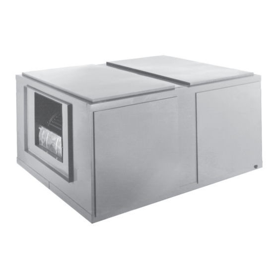
2.7 MAJOR COMPONENTS EVAPORATOR FILTERS COIL EITHER CABINET MOTOR SIDE REFRIGERANT CONNECTION LOCATION Unit shown with side panel removed for coil connections and air filter access. Low Voltage Terminal Block (TB2) Control Box Line Voltage Terminal Block (TB1) Variable Frequency Drive (VFD) Note: Remove panel with unit data plate to access this compartment... -
Page 11: Importance Of Proper Indoor/Outdoor Match-Ups
2.8 IMPORTANCE OF PROPER INDOOR/OUTDOOR MATCH-UPS www.ahridirectory.org 2.9 IMPORTANCE OF A QUALITY INSTALLATION IMPORTANT:... -
Page 12: Installation
3.0 INSTALLATION 3.1 TOOLS & REFRIGERANT 3.1.1 TOOLS REQUIRED FOR INSTALLING AND SERVICING R-410A MODELS Manifold Sets: Ambient and Tube Thermometers Crescent Wrench Manifold Hoses: Allen Wrench Manifold Gauge Recovery Cylinders: Brazing Recovery Rods Cylinders NOTICE R-410A systems operate at higher pressures than R-22 systems. -
Page 13: Applications & Orientation
3.2 APPLICATIONS & ORIENTATION IMPORTANT: 3.2.1 HORIZONTAL DISCHARGE FIGURE 2 HORIZONTAL DISCHARGE VERTICAL VERTICAL RETURN AIR RETURN AIR OPTION #1 OPTION #2 HORIZONTAL SUPPLY AIR RETURN AIR ST-A1293-02 HORIZONTAL DISCHARGE 3.2.2 VERTICAL UP DISCHARGE ST-A1293-02 FIGURE 3 VERTICAL UP DISCHARGE SUPPLY AIR VERTICAL RETURN AIR... -
Page 14: Applications Requiring Electric Heat
3.2.3 APPLICATIONS REQUIRING ELECTRIC HEAT FIGURE 4 APPLICATIONS REQUIRING ELECTRIC HEAT 3.2.4 SUSPENDING UNIT 3.2.5 INSTALLATION IN AN UNCONDITIONED SPACE 3.2.6 INSTALLATION IN CORROSIVE ENVIRONMENTS... -
Page 15: Auxiliary Overflow Pan
3.3 AUXILIARY OVERFLOW PAN 3.4 CLEARANCES 3.5 DUCTWORK WARNING Do not, under any circumstances, connect return ductwork to any other heat producing device such as fireplace insert, stove, etc. Unauthorized use of such devices may result in fire, carbon monoxide poisoning, explo- sion, personal injury or property damage. -
Page 16: Refrigerant Line Connections & Charging
3.7 REFRIGERANT LINE CONNECTIONS & CHARGING 3.7.1 PREPARATION 3.7.2 CONFIGURING AIR-HANDLER FOR A SINGLE OR DUAL REFRIGERANT CIRCUITS FIGURE 5... -
Page 17: Refrigerant Lines
3.7.3 REFRIGERANT LINES SUCTION EQUIV. LIQUID LINE O.D. LENGTH TO LINE O.D. EVAP. (FT.) 10 [35kW] 0-50 [0-15m] 5/8 [26mm] 1 3/8 [35mm] 51-100 [16-30m] 5/8 [26mm] 1 5/8 [41mm] 101-150 [31-46m] 5/8 [26mm] 1 5/8 [41mm] 3.7.4 LIQUID LINE FILTER DRIER... -
Page 18: Brazing
3.7.5 BRAZING 3.7.6 LEAK TESTING 3.7.7 EVACUATION 3.7.8 REFRIGERANT CHARGING 3.8 TXV SENSING BULB ATTACHMENT IMPORTANT: FIGURE 6 BULB LOCATION – HORIZONTAL SECTION OF VAPOR LINE... -
Page 19: Condensate Drain
3.9 CONDENSATE DRAIN IMPORTANT: IMPORTANT: FIGURE 7 CONDENSATE DRAIN TRAP 3.10 THERMOSTAT... -
Page 20: Electrical Wiring
3.11 ELECTRICAL WIRING 3.11.1 POWER WIRING • IMPORTANT: 3.11.1.1 NO-HEAT APPLICATIONS 3.11.1.2 ELECTRIC HEAT APPLICATIONS IMPORTANT: 3.11.2 GROUNDING WARNING The unit must be permanently grounded. Failure to do so can result in electri- cal shock causing personal injury or death. -
Page 21: Electrical Data - Without Electric Heat
3.11.3 ELECTRICAL DATA – WITHOUT ELECTRIC HEAT AIR HANDLER MOTOR RECOMMENDED MAXIMUM MINIMUM DRIVE MINIMUM COPPER OVERCURRENT "RATING MODEL NUMBER CIRCUIT "MOTOR PACKAGE WIRE SIZE/ MAX. RUN PROTECTION VOLTS PHASE PLATE AMPACITY LRA" IN FEET AMPS AMPS" (-)HCLA2090C 208/230 #14 / 165 (-)HCLA2090D #14 / 275 (-)HCLA2090C... -
Page 22: Electric Heater Kit Identification Label
3.11.6 ELECTRIC HEATER KIT IDENTIFICATION LABEL FIGURE 8 3.11.7 CONTROL WIRING IMPORTANT: TABLE 1 3.11.7.1 NO-HEAT APPLICATIONS 3.11.7.2 ELECTRIC HEAT APPLICATIONS 3.11.7.3 CONFIGURING OUTDOOR UNIT TRANSFORMER FOR 208V APPLICATIONS... -
Page 23: Wiring Connection Diagrams
3.11.8 WIRING CONNECTION DIAGRAMS... -
Page 24: Air-Flow
3.12 AIR-FLOW The air-handler is equipped with a Variable Frequency Drive (VFD) that provides a reduction in air-flow in the continuous fan mode, 1 stage cooling mode, and 1 stage heat pump heating mode. Full air-flow is delivered for the 2 stage of cooling mode, 2 stage of heat pump heating mode, and all stages of electric heat. - Page 25 3.12.2 AIR-FLOW PERFORMANCE DATA (DRY COIL) - RHCLP2120...
-
Page 26: Air-Flow Performance Data
3.12.2 AIR-FLOW PERFORMANCE DATA (DRY COIL) - RHCL(-)2090 - CONT. -
Page 27: Component Air-Resistance Data
3.12.3 COMPONENT AIR-RESISTANCE DATA 1800 2200 2600 3000 3400 3800 4200 4600 5000 [L/s] [850] [1038] [1227] [1416] [1605] [1793] [1982] [2171] [2360] Electric Heater 20KW, 30KW .060 [.015] .100 [.025] .140 [.034] .160 [.040] .230 [.057] .320 [.080] .410 [.102] .500 [.124] .600 [.150] Mixing Box (R/A Damper Open) .006 [.001] .008 [.002] .012 [.003] .024 [.006] .038 [.009] .053 [.013] .068 [.017] .080 [.020] .095 [.024] Discharge Grille (Set Max. -
Page 28: Drive Belt Alignment & Adjustment
3.12.7 DRIVE BELT ALIGNMENT & ADJUSTMENT FIGURE 9 Place belt on the groove of the blower sheave and motor sheave to obtain the approx- imate alignment and belt tension. Remove the belt and align the blower sheave and motor sheave using a straight edge. When both sheaves are properly aligned, re-install belt. -
Page 29: Checking Indoor Air-Flow Rate
4.3 CHECKING INDOOR AIR-FLOW RATE 4.3.1 ESTIMATING AIR-FLOW RATE USING EXTERNAL STATIC PRESSURE A common method of checking indoor is to measure the external static pressure that the air-handler is working against and then referring to the air-flow data in Section 3.12. Measuring external static pressure to a high degree of precision in the field is challeng- ing, so keep in mind that the air-flow rate determined by this method is an estimate, but is accurate enough for all practical purposes. -
Page 30: Sequence Of Operation
4.5 SEQUENCE OF OPERATION 4.5.1 COOLING & HEAT PUMP HEATING MODES When the 2-stage thermostat calls for 1st stage of cooling or heat pump heating and the thermostat fan setting is set to the AUTO position, the G signal from the thermostat causes the Variabe Frequency Drive (VFD) to ramp the motor to the low speed air-flow level (37.5 Hz) which is 63% of full air-flow. -
Page 31: Field Installed Accessories & Kits
5.0 FIELD INSTALLED ACCESSORIES & KITS ACCESSORY MODEL SIZE NET WEIGHT DESCRIPTION NUMBER USED ON (LBS) [kg] RXHC-C74W 090,120 200 [91] Hot Water Coil RXHC-C76W 150,180,240 200 [91] RXHC-C74S 090,120 200 [91] Steam Coil RXHC-C76S 150,180,240 200 [91] RXHF-B74A 090,120 90 [41] Filter Frame Coil RXHF-B76A... -
Page 32: Mixing Box Kits
5.2 MIXING BOX KITS ACCESSORY MODEL RXHM-A74F COOLING SEASON—Thermostat set at “Cool” and “Fan Auto,” outside air damper goes to “minimum fresh air” position HEATING SEASON—Damper always stays at “minimum fresh when cooling thermostat closes, energizing mechanical cool- air” position while fan motor is operating. Outside air damper ing. - Page 33 5.2 MIXING BOX KITS (continued) Field - Installed Mixing Box Dimensions TOP VIEW ENTHALPY CONTROL FRONT VIEW SIDE VIEW FLANGED DUCT OPENING IN. [mm] AIR HANDLER MODEL NO. SIZES USED ON LENGTH IN. [mm] WIDTH IN. [mm] “X” RXHMBC-74H 090, 120 42 [1067] [1229] 27 [686]...
-
Page 34: Discharge Plenum, Discharge Grille, & Inlet Grille Kits
5.3 DISCHARGE PLENUM, DISCHARGE GRILLE, & INLET GRILLE KITS... -
Page 35: Filter Frame Kits
5.4 FILTER FRAME KITS The filter rack accessory can be connected directly to the hot FILTER PRESSURE DROP: water/steam coil accessory. IN. [mm] MODEL RXHF-B74A [1308] [610] [638] [1203] [505] [52] [ ] Designates Metric Conversions... -
Page 36: Hot Water & Steam Coils
5.5 HOT WATER & STEAM COILS [ ] Designates Metric Conversions... -
Page 37: Maintenance
6.0 MAINTENANCE For continuing high performance, and to minimize possible equipment failures, it is essential that periodic maintenance be performance on this equipment. This section provides general guidelines on what items require periodic maintenance and the recom- mended frequency for maintenance. 6.1 AIR-FILTERS Check the system filter every 30-90 days or as often as found to be necessary depend- ing on the application. -
Page 38: Diagnostics
7.0 DIAGNOSTICS Problem Possible Cause (Suggested Fix) Blower motor will not • Failed run capacitor (H voltage only) operate or no air-flow • Failed motor (replace) • Loose wiring connection or broken wire (check connections & wiring) • Failed transformer on outdoor unit (replace) •... -
Page 39: Wiring Diagram
8.0 WIRING DIAGRAM... - Page 40 97B0136N01 | CM 0418...
Need help?
Do you have a question about the HCLA2090CAR and is the answer not in the manual?
Questions and answers