Table of Contents
Advertisement
Quick Links
- 1 Table of Contents
- 2 Operation Parameters
- 3 Technical Data
- 4 Control Gear Construction
- 5 Control Circuit
- 6 Connection Controller Diagram
- 7 Appendix 1 Circuit Diagram of "Cbx Upc3 3X400V 2X1Vfd <2,2Kw" Control Gear
- 8 Appendix 2 Circuit Diagram of "Cbx Upc3 3X400V 2X1Vfd <11Kw" Control Gear
- Download this manual
Advertisement
Table of Contents

Related Manuals for VTS Medical Systems uPC3 3x400V 2x1VFD 2,2kW

Summary of Contents for VTS Medical Systems uPC3 3x400V 2x1VFD 2,2kW
- Page 1 Control gear for Supply and Supply-Exhaust Air Handling Units The control gear complies with European Standard IEC 61439-2: Power switchgear and control gear assemblies ver.1.3 (10.2019) VTS reserves the right to implement changes without prior notice...
-
Page 2: Table Of Contents
Table of contents Table of contents ........................................2 SAFETY INSTRUCTIONS AND ALARMS! ..................................3 Technical data ........................................4 Control gear construction ....................................4 Main internal elements:..................................... 4 Operation parameters ....................................... 4 Short-circuit and overload protection................................. 5 Relay pump ........................................5 Control circuit........................................ -
Page 3: Safety Instructions And Alarms
SAFETY INSTRUCTIONS AND ALARMS! Prior to installation and use of the unit, please read this Manual carefully. Installation, connection and maintenance shall be executed by a qualified specialist considering the local rules, normative acts and practice. Prior to connecting peripherals to the board, please read the Manual. The Company shall not assume any liability for personal injuries or damage to property in case of failure to observe these safety requirements, if the product is modified without manufacturer’s consent Electrical power switching and unit maintenance shall be performed only by qualified employee following the manufacturer manual and applicable... -
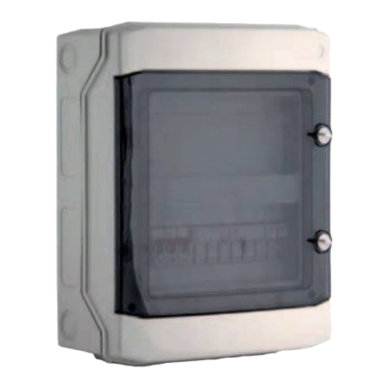
Page 4: Technical Data
Technical data Control gear construction Casing with external mains switch and RJ11 port for connecting the HMI Advanced control panel Main internal elements: short-circuit and overload protection assemblies connection units CAREL µPC3 XS controller Operation parameters System ... -
Page 5: Short-Circuit And Overload Protection
Control circuit Short-circuit and overload protection Relay outputs Supply VFD, EC motors 1F1M – 1F5M (gG32A) (NO1, NO2, NO3) – C1; (NO4, NO5, NO6)-C2; NO7-C7 Exhaust VFD, EC motors 2F1M – 2F5M (gG32A) Analog inputs Water pump, rotary wheel drive F1 (B6) ... - Page 6 Table I/O (for application ver. to 1.0.005) UPC3 UPC3 Supply Analog Inputs +24V DC Temp. Supply -24V DC Temp. Return (Room) / PreHeater (for Compact AHU) Digital Inputs Temp. External Fire Alarm Temp. Exhaust Heater Alarm / DXH Alarm Temp. Water Heater Cooler Alarm / DXH Alarm Temp.
-
Page 7: Connection Controller Diagram
Connection controller diagram VTS reserves the right to implement changes without prior notice... -
Page 8: Dimensions And Weight
Dimensions and weight CBX NAME Weight [kg] Dimensions (w x h x d) uPC3 3x400V 2x1VFD <2,2kW 3,85 390x317x150 uPC3 3x400V 2x1VFD <11kW 390x317x150 uPC3 3x400V 2x2VFD <11kW 540x317x150 uPC3 3x400V 2x3VFD <11kW 657x455x160 uPC3 3x400V 2x4VFD <11kW, 2x5VFD <7,5kW 693x455x160 3x400V 1x1VFD <11kW 3,95... -
Page 9: Cabling
Cabling Connect power leads of the control gear and frequency converter of the fan drive according to the Electric diagram. The wire cross-sections have been selected for long term current capacity for cables arranged in the air (supported on brackets, cable racks, in perforated trays) with spacing from the wall of min. - Page 10 Table A Motor rated Motor rated FC supply FC protection Motor cable Control gear power supply cable Control gear rated current power current cable [mm 2 ] [mm 2 ] [mm 2 ] [kW] supply AHU supply- exhaust supply- 3~230V / 50Hz 1~230V / 50Hz supply AHU L1 1~230V...
- Page 11 Table B Motor power 7,5kW 11kW 2x4kW 2x5,5kW 2x7,5kW 2x11kW 3x4kW 3x5,5kW [kW] only supply 17,0 16,5 22,0 23,0 22,5 28,0 18,0 17,5 23,0 24,0 23,5 29,0 32,0 31,5 37,0 44,0 43,5 49,0 26,0 25,5 31,0 35,0 34,5 40,0 0,55kW 0,75kW 1,1kW 1,5kW...
- Page 12 Table B Motor power 3x7,5kW 3x11kW 4x4kW 4x5,5kW 4x7,5kW 4x11kW [kW] only supply 47,0 46,5 52,0 65,0 64,5 70,0 34,0 33,5 39,0 46,0 45,5 51,0 62,0 61,5 67,0 86,0 85,5 91,0 0,55kW 0,75kW 1,1kW 1,5kW 2,2kW 5,5kW 7,5kW 11kW 2x4kW 2x5,5kW 2x7,5kW 2x11kW...
- Page 13 Table C Motor power [kW] 0,55kW 0,75kW 1,1kW 1,5kW 2,2kW 5,5kW 7,5kW 11kW 2x4kW 2x5,5kW 2x7,5kW 2x11kW 3x4kW 3x5,5kW 3x7,5kW 3x11kW 4x4kW 4x5,5kW 4x7,5kW 4x11kW 0,55kW 0,75kW 1,1kW 1,5kW 2,2kW 5,5kW 7,5kW 11kW 2x4kW 2x5,5kW 2x7,5kW 2x11kW 3x4kW 3x5,5kW 3x7,5kW 3x11kW 16 (2x) 16 (2x)
-
Page 14: Appendix 1 Circuit Diagram Of "Cbx Upc3 3X400V 2X1Vfd <2,2Kw" Control Gear
Appendix 1 Circuit diagram of “CBX uPC3 3x400V 2x1VFD <2,2kW” control gear 2x1 motors 1x230V / 3x400V from 0,75kW to 2,2kW VTS reserves the right to implement changes without prior notice... - Page 15 VTS reserves the right to implement changes without prior notice...
-
Page 16: Appendix 2 Circuit Diagram Of "Cbx Upc3 3X400V 2X1Vfd <11Kw" Control Gear
Appendix 2 Circuit diagram of “CBX uPC3 3x400V 2x1VFD <11kW” control gear 2x1 3x400V from 0,75kW to 11kW VTS reserves the right to implement changes without prior notice... - Page 17 VTS reserves the right to implement changes without prior notice...
-
Page 18: Appendix 3 Circuit Diagram Of "Cbx Upc3 3X400V 2X2Vfd <11Kw" Control Gear
Appendix 3 Circuit diagram of “CBX uPC3 3x400V 2x2VFD <11kW” control gear 2x2 motors 3x400V from 0,75kW to 11kW VTS reserves the right to implement changes without prior notice... - Page 19 VTS reserves the right to implement changes without prior notice...
-
Page 20: Appendix 4 Circuit Diagram Of "Cbx Upc3 3X400V 2X3Vfd <11Kw" Control Gear
Appendix 4 Circuit diagram of “CBX uPC3 3x400V 2x3VFD <11kW” control gear 2x3 motors 3x400V from 0,75kW to 11kW VTS reserves the right to implement changes without prior notice... - Page 21 VTS reserves the right to implement changes without prior notice...
-
Page 22: Appendix 5 Circuit Diagram Of "Cbx Upc3 3X400V 2X4Vfd <11Kw, 2X5Vfd <7,5Kw" Control Gear
Appendix 5 Circuit diagram of “CBX uPC3 3x400V 2x4VFD <11kW, 2x5VFD <7,5kW” control gear 2x5 motors 3x400V from 0,75kW to 11kW VTS reserves the right to implement changes without prior notice... - Page 23 VTS reserves the right to implement changes without prior notice...
-
Page 24: Appendix 6 Circuit Diagram Of "Cbx Upc3 3X400V 1X1Vfd <11Kw" Control Gear
Appendix 6 Circuit diagram of “CBX uPC3 3x400V 1x1VFD <11kW” control gear 1x1 motors 3x400V from 0,75kW to 11kW VTS reserves the right to implement changes without prior notice... -
Page 25: Appendix 7 Circuit Diagram Of Control Circuit
Appendix 7 Circuit diagram of control circuit Suitable for all type of control gears VTS reserves the right to implement changes without prior notice... - Page 26 VTS reserves the right to implement changes without prior notice...
Need help?
Do you have a question about the uPC3 3x400V 2x1VFD 2,2kW and is the answer not in the manual?
Questions and answers