Advertisement
Quick Links
Manufacturer
Hoffmann Supply Chain GmbH
Franz-Hoffmann-Str. 3, 90431 Nuremberg
Germany
www.hoffmann-group.com
1✕
927140
2✕
927142
4✕
4✕
927140
927140
M6
8✕
8✕
927142
927142
A
1
2
3
B
1
2
2✕
C
2✕
de
GridLine Rückwand/Ablageboden
1.
Identifikationsdaten
Version
02 Originalbedienungsanleitung
Erstellungsdatum 07/2020
2.
Allgemeine Hinweise
Bedienungsanleitung lesen, beachten, für späteres
Nachschlagen aufbewahren und jederzeit verfüg-
bar halten.
3.
Sicherheit
3.1
BESTIMMUNGSGEMÄSSE VERWENDUNG
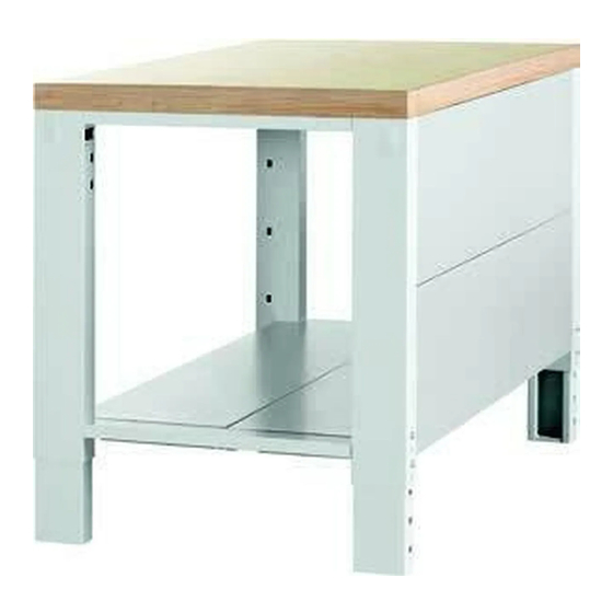
Rückwand oder Ablageboden zur Montage an Fußteil
der GridLine vario Werkbank.
Montage als Ablageboden nur in Kombination mit
Knotenblechen Nr. 971722.
Größe 1000 zur Montage als Rückwand an Eck-Stütz-
fuß.
Ablageboden zur Aufbewahrung von Werkstücken und
Werkzeugen.
Rückwand als Sichtschutz und zur Stabilisierung der
Werkbank.
Nur an Werkbank mit zwei Fußteilen montieren.
Nur an entsprechenden Bohrungen montieren.
Maximale Tragfähigkeiten beachten.
3.2
PERSÖNLICHE SCHUTZAUSRÜSTUNG
Nationale und regionale Vorschriften zur Sicherheit und
Unfallverhütung beachten. Schutzkleidung wie Fußschutz
und Schutzhandschuhe müssen entsprechend der bei der
jeweiligen Tätigkeit zu erwartenden Risiken gewählt und
bereitgestellt werden.
4.
Montagehinweise
i
Bei Montage als Rückwand sind im hinteren Bereich keine
Knotenbleche notwendig.
4.1
KÄFIGMUTTERN EINSETZEN
A
i
Je Rückwand: Am Kopf- oder Fußende je Fußteil zwei Kä-
figmuttern in Ausstanzung auf Innenseite montieren.
Je Ablageboden: An unterer Querverstrebung je Fußteil zwei
Käfigmuttern in Ausstanzung auf Innenseite montieren.
1.
Käfigmutter von vorne schräg in Ausstanzung
einsetzen.
2.
Mit Schraubendreher nach hinten schieben,
festklipsen.
4.2
RÜCKWAND/ABLAGEBODEN
B /
C
i
Rückwand auf Rückseite der Werkbank montieren.
Ablageboden in untere Querverstrebung der Fußteile mon-
tieren.
Bei Montage Ausstanzungen Kabelkanäle beachten.
GARANT GridLine Rückwand/
Ablageboden
927140 - 927142
Montageanleitung
Installation instructions |
Instrucciones de montaje |
Instructions de montage |
Istruzioni di montaggio |
Instrukcja montażu
Rückwand/Ablageboden mit zwei Sechskantschrauben
M6 pro Fußteil mit Käfigmuttern verschrauben.
5.
Technische Daten
Abmessungen
Artikelnummer
Größe
Breite
927140,
1000
900 mm
927142
1500
1400 mm
2000
1900 mm
Tragfähigkeiten Ablageboden
Artikelnummer
Tragfähigkeit flächenverteilt
927140,
100 kg
927142
5.1
BELASTUNGSMATRIX
i
Belastungsangaben für GridLine vario Werkbank mit
Plattenlänge 1000 – 2000 mm.
Kombinationsmöglichkeiten
1×Arbeitsplatte
1×Arbeitsplatte
2×Fußteile
2×Fußteile
2×Rückwand ein-
1×Schubladenge-
zeln
häuse hängend
2×Knotenbleche
2×Rückwand ein-
zeln
2×Knotenbleche
en
GridLine rear panel/storage shelf
1.
Identification data
Version
02 Translation of the original in-
struction manual
Date created
07/2020
2.
General instructions
M6✕12
Read the instructions for use, follow them and
keep them available for later reference.
3.
Safety
3.1
INTENDED USE
Rear panel or storage shelf for installation on the sup-
port leg of the GridLine vario workbench.
Installation as a storage shelf only in conjunction with
the stabilising plate No. 971722.
Size 1000 for installation as a rear panel on a corner
support leg.
Storage shelf for storage of workpieces and tools.
Rear panel as a modesty board and for stabilising the
workbench.
Perform installation only on a workbench with two
support legs.
Mount only on suitable holes.
Comply with the maximum load capacity.
3.2
PERSONAL PROTECTIVE EQUIPMENT
Comply with the national and regional regulations for sa-
fety and accident prevention. Protective work wear such as
safety shoes and safety gloves appropriate for the risks as-
sociated with the intended activities must be selected and
provided.
4.
Installation instructions
i
When installed as a rear panel, no stabilising plate is ne-
cessary.
4.1
USE CAGE NUTS
A
i
For each rear panel: At the top end or foot end of each
support leg, install two cage nuts on the inside punched re-
cess.
For each storage shelf: At the lower cross brace of each sup-
port leg, install two cage nuts on the inside punched recess.
1.
Insert the cage nuts obliquely from the front in the
punched recess.
2.
Use a screwdriver to push them back and clip them se-
curely into position.
4.2
REAR PANEL / STORAGE SHELF
B /
C
i
Install the rear panel at the rear of the workbench.
Install the storage shelf in lower cross brace of each support
leg.
During installation, leave the punched recesses for the
cable ducts clear.
Secure the rear panel/support shelf to each support
foot with two M6 hex-head screws with cage nuts.
5.
Technical data
Dimensions
Article num-
Size
Width
ber
927140,
1000
900 mm
927142
1500
1400 mm
Article num-
Size
ber
de
2000
Load capacities of storage shelves
Article num-
Load capacity, distributed
ber
en
927140,
100 kg
927142
5.1
LOADING MATRIX
i
Loading data for GridLine vario workbench with worktop
es
length 1000 – 2000 mm.
Available combinations
1×worktop
1×worktop
2×support legs
2×support legs
fr
2×rear panels
1×suspended
2×stabilising pla-
drawer casing
tes
2×individual
rear panels
it
2×stabilising
plates
Panel posterior/estante de
es
pl
almacenamiento GridLine
1.
Datos de identificación
Versión
Fecha de creación
2.
Indicaciones generales
Lea, observe y conserve el manual de instrucciones
de uso para consultas posteriores, y téngalo siemp-
Tiefe
re a mano.
300 mm
3.
Seguridad
300 mm
3.1
USO CONFORME A LO PREVISTO
300 mm
Panel posterior o estante de almacenamiento para el
montaje en pie soporte del banco de trabajo GridLine
vario.
Montaje como estante de almacenamiento solo en
combinación con chapas de nudos n.º 971722.
Tamaño 1000 para el montaje como panel posterior en
el pie de soporte de esquina.
Estante de almacenamiento para guardar piezas de tra-
bajo y herramientas.
Panel posterior como protección visual y para la estabi-
Flächenverteilte,
lización del banco de trabajo.
ruhende Last
Montar solo en banco de trabajo con dos pies soporte.
600 kg
Montar solo en las perforaciones correspondientes.
Tener en cuenta las capacidades de carga máximas.
3.2
EQUIPO DE PROTECCIÓN INDIVIDUAL
Tener en cuenta las normas nacionales y regionales en
cuanto a seguridad y prevención de accidentes. La ropa de
protección como protección para los pies y guantes pro-
tectores se han de seleccionar y disponer de acuerdo con
los riesgos propios de la actividad correspondiente.
4.
Indicaciones para el montaje
i
En caso de montaje como panel posterior no se necesita
ninguna chapa de nudos en la zona posterior.
4.1
COLOCAR LAS TUERCAS DE JAULA
A
i
En cada panel posterior: En los extremos inferior o supe-
rior de cada pie soporte montar dos tuercas de jaula en el re-
corte por la superficie interior.
En cada estante de almacenamiento: En el arriostramiento
transversal inferior de cada pie soporte montar dos tuercas de
jaula en la perforación por la superficie interior.
1.
Inserte la tuerca enjaulada diagonalmente desde el
frente en el corte.
2.
Empujarla hacia atrás con un destornillador y engan-
charla.
4.2
PANEL POSTERIOR/ESTANTE DE
ALMACENAMIENTO
B /
C
i
Montar el panel posterior en la parte posterior del banco
de trabajo.
Montar el estante de almacenamiento en el arriostramien-
to transversal inferior de los pies soporte.
En el montaje prestar atención a los recortes de los
canales para cable.
Atornillar el panel posterior/estante de almacenamien-
to a las tuercas de jaula con dos tornillos de cabeza he-
xagonal M6 por pie soporte.
5.
Especificaciones técnicas
Medidas
Número de
Tamaño
artículo
927140,
1000
927142
1500
2000
Capacidad de carga estante de almacenamiento
Número de
Capacidad de carga distribuida en la su-
artículo
perficie
927140,
100 kg
927142
5.1
MATRIZ DE CARGA
i
Datos de carga para banco de trabajo GridLine vario con
longitud de tablero 1000-2000 mm.
Posibilidades de combinación
1 tablero de traba-
1 tablero de
jo
trabajo
2 pies soporte
2 pies soporte
2 paneles poste-
1 carcasa de
riores individuales
cajones sus-
2 chapas de nudos
pendida
2 paneles pos-
teriores indivi-
duales
Depth
2 chapas de
nudos
300 mm
300 mm
Width
Depth
Paroi arrière/Plateau de rangement
fr
GridLine
1900 mm
300 mm
1.
Données d'identification
Version
Date de création
2.
Remarques générales
Lisez, respectez et conservez le mode d'emploi à
des fins de consultation ultérieure, et gardez-le
toujours à disposition.
Distributed non-dy-
3.
Sécurité
namic load
3.1
UTILISATION NORMALE
600 kg
Paroi arrière ou plateau de rangement pour montage
sur un piètement d'un établi GridLine vario.
Montage comme plateau de rangement uniquement
en combinaison avec les goussets 971722.
Réf. 1000 pour montage comme paroi arrière sur un
pied d'appui d'angle.
Plateau pour le rangement de pièces et d'outils.
Paroi arrière comme protection contre les regards in-
discrets et pour stabilisation de l'établi.
Monter uniquement sur des établis avec deux piète-
ments.
Monter uniquement sur les trous correspondants.
Respecter les charges admissibles maximales.
3.2
EQUIPEMENT DE PROTECTION INDIVIDUELLE
02 Traducción del manual de
Respecter les réglementations nationales et régionales en
instrucciones original
matière de sécurité et de prévention des accidents. Les
07/2020
vêtements de protection, tels que les chaussures et les
gants, doivent être choisis et mis à disposition en fonction
des risques prévus pendant l'activité concernée.
4.
Consignes de montage
i
En cas de montage comme paroi arrière, il n'est pas néces-
saire d'installer des goussets à l'arrière.
4.1
MISE EN PLACE DES ÉCROUS CAGE
A
i
Par paroi arrière : monter deux écrous cage par piète-
ment dans la découpe sur la paroi intérieure en haut ou en
bas du pied.
Par plateau de rangement : monter deux écrous cage par
piètement dans la découpe sur la paroi intérieure au niveau
du renfort transversal inférieur.
1.
Insérez l'écrou cage en diagonale dans la découpe
avant.
2.
Pousser vers l'arrière à l'aide d'un tournevis, clipser fer-
mement.
4.2
PAROI ARRIÈRE/PLATEAU DE RANGEMENT
B /
C
i
Monter la paroi arrière à l'arrière de l'établi.
Monter le plateau de rangement dans le renfort transversal
inférieur des piètements.
Lors du montage, tenir compte des découpes des con-
duites de câbles.
Visser la paroi arrière/le plateau de rangement aux
écrous cage à l'aide de deux vis à 6 pans M6 par piète-
ment.
5.
Caractéristiques techniques
Dimensions
Code article Réf.
927140,
1000
927142
1500
2000
Charges admissibles du plateau de rangement
Code article Charge admissible répartie sur la surface
927140,
100 kg
927142
5.1
TABLEAU DES CHARGES
i
Indications de charge pour les établis GridLine vario avec
longueur de plan de travail de 1 000 – 2 000 mm.
Possibilités de combinaisons
1×plan de travail
2×piètements
2×parois arrière
individuelles
2×goussets
it
Anchura
Profundidad
Parete posteriore/mensola GridLine
1.
Dati identificativi
900 mm
300 mm
Versione
1400 mm
300 mm
1900 mm
300 mm
Data di creazione
2.
Note generali
Leggere il manuale d'uso, rispettarlo, conservarlo
per riferimento futuro e tenerlo sempre a portata
di mano.
3.
Sicurezza
3.1
USO PREVISTO
Parete posteriore o mensola da montare alle strutture
portanti del banco da lavoro GridLine vario.
Caga distribuida en
Montaggio come mensola solo in combinazione con i
la superficie, en re-
raccordi a gomito n. art. 971722.
poso
Dim. 1000 adatta per il montaggio come parete poste-
600 kg
riore al piedino di appoggio angolare.
Mensola per la custodia di pezzi e utensili.
La parete posteriore funge da protezione visiva e ga-
rantisce una maggiore stabilità del banco da lavoro.
Montare solo sui banchi da lavoro con due strutture
portanti.
Montare solo nei fori corrispondenti.
Rispettare la portata massima prevista.
02 Traduction du manuel
d'instructions original
07/2020
Largeur
Profondeur
900 mm
300 mm
1400 mm
300 mm
1900 mm
300 mm
Charge statique,
uniformément
répartie
1×plan de tra-
600 kg
vail
2×piètements
1×caisson de
tiroirs suspen-
du
2×parois arriè-
re individuelles
2×goussets
02 Traduzione del manuale
di istruzioni originale
07/2020
Advertisement

Subscribe to Our Youtube Channel
Related Manuals for GARANT GridLine 927140


Summary of Contents for GARANT GridLine 927140
- Page 1 Article num- Size Width Depth Paroi arrière/Plateau de rangement GARANT GridLine Rückwand/ GridLine 2000 1900 mm 300 mm Ablageboden Load capacities of storage shelves Données d'identification Article num- Load capacity, distributed Version 02 Traduction du manuel 927140 - 927142 d'instructions original 927140, 100 kg...
- Page 2 DISPOSITIVI DI PROTEZIONE TYLNA ŚCIANA/PÓŁKI ANTINFORTUNISTICI Osservare le norme nazionali e regionali in materia di sicu- Tylną ścianę zamontować z tyłu stołu warsztatowego. rezza e prevenzione degli infortuni. L’abbigliamento di Półkę zamontować na dolnym usztywnieniu poprzecznym protezione, come scarpe di sicurezza e guanti protettivi, segmentu nóg.
Need help?
Do you have a question about the GridLine 927140 and is the answer not in the manual?
Questions and answers