Advertisement
VITALink® MC/RC90
Fire-Resistive Cable Certified by UL and ULC
VITALink® MC/RC90 Cables
Systems 120/120A/60
Installation Instructions
These instructions apply to listed fire-resistive cable. See applicable systems
under "Listings/Certifications/Compliance" on this page. See NFPA 70 Article
728 for a description of Fire-Resistive Cable Systems and their requirements.
Compliance and verification is summarized on the last page. This document
outlines the minimum installation requirements.
The requirements for fire resistive rated systems are more stringent
modifications to the installation rules in the NEC and CE Code. Industry
standard installation practices and workmanship shall be exercised in all
installations. Follow NEC or CE Code rules for cables installed in areas that are
fire protected (Ex. Electrical rooms, etc). Read all instructions before starting.
Description
RSCC's VITALink® MC/RC90 cable is both UL and cUL listed electrically and fire-
resistive rated for a maximum of 2 hours to UL 2196/ULC S139 for USA and
Canada in sizes 14 AWG through 750 kcmil. The cable is compliant with the
NEC
1
and Canadian Electrical Code (CE CODE) requirements. The installation
instructions pertain to installing the cable for a 2 hour system therefore, the
cable system described within can be used for RSCC's 1 hour or 2 hour fire
resistive rated VITALink® MC/RC90 systems.
VITALink® MC/RC90 cable is rated at 600 volts maximum (phase to phase) and
is compliant with the NEC
1
requirements for Type MC and and RC90 respectively.
Cable sizes and constructions range from 14 AWG through 750 kcmil and
single conductor to twelve conductor. A complete list of available
constructions is provided within this document and on UL's website under
FHJR R15365 for USA and FHJR7 R15365 for Canada.
Once a fire resistive rated splice is introduced into the system, please limit the
system use to the hourly fire resistance rating, max voltage and current
allowed for the splice.
RSCC Wire & Cable LLC © 2020 • 20 Bradley Park Road • East Granby, CT 06026 USA • 800-327-7625 Tel: 860-653-8300 • Fax: 860-653-8321 •
and Canadian Electrical Code (CE CODE)
Materials Required
Only the components listed in these instructions shall be used to maintain the
respective fire resistive rating. Further details on the materials beyond the list
below are provided inside the document.
1. VITALink® MC/RC90 Cable with or without an overall polymeric
with or without ground(s) or segmented
2. Steel mounting components.
For more information on the certification, please see the system published in
the UL website.
Tools Required
• Utility Knife
• Socket Wrench
• Screw Driver
Listings/Certifications/Compliance
The fire resistive cable Certified by UL to UL 2196 and ULC to ULC S139 for use
in the following systems:
2 Hour FHIT/FHIT7 120
2 Hour FHIT/FHIT7 120A
1 Hour FHIT/FHIT7 60
VITALink® MC/RC90 Cable
• Type MC per UL 1569
• Type RC90 per CSA C22.2 No. 123
• See VITALink® MC/RC90 data sheet for other cable listings and certifications
groundwire(s).
• Pipe Cutter
• Cable Cutter
r-scc.com
IM-120-0
Rev 0
7/31/2020
jacket, and
1/7
Advertisement
Table of Contents

Summary of Contents for MARMON VITALink MC
- Page 1 VITALink® MC/RC90 IM-120-0 Fire-Resistive Cable Certified by UL and ULC VITALink® MC/RC90 Cables Rev 0 Systems 120/120A/60 7/31/2020 Materials Required Installation Instructions Only the components listed in these instructions shall be used to maintain the These instructions apply to listed fire-resistive cable. See applicable systems respective fire resistive rating.
- Page 2 VITALink® MC/RC90 IM-120-0 Fire-Resistive Cable Certified by UL and ULC VITALink® MC/RC90 Cables Rev 0 Systems 120/120A/60 7/31/2020 General This document outlines the minimum installation requirements for installing a cable to the systems described above. Electrical Circuit Integrity Systems consist of components and materials that are intended for installation as protection for specific electrical wiring systems, with respect to the disruption of electrical circuit integrity upon exterior fire exposure.
- Page 3 VITALink® MC/RC90 IM-120-0 Fire-Resistive Cable Certified by UL and ULC VITALink® MC/RC90 Cables Rev 0 Systems 120/120A/60 7/31/2020 supported/secured to a 2 hour structure no greater than three feet for EMT or IMC is acceptable for wall penetrations or short sections. Conduits lengths greater than 5 ft.
- Page 4 VITALink® MC/RC90 IM-120-0 Fire-Resistive Cable Certified by UL and ULC VITALink® MC/RC90 Cables Rev 0 Systems 120/120A/60 7/31/2020 J-800 1-Piece Figure 1 Tray Cables laid in steel tray shall neatly arranged and be secured with steel banding or steel ties every four feet. Cables shall be installed snug, but not excessively where cable is damaged.
- Page 5 VITALink® MC/RC90 IM-120-0 Fire-Resistive Cable Certified by UL and ULC VITALink® MC/RC90 Cables Rev 0 Systems 120/120A/60 7/31/2020 Terminating at Switchgear/Equipment When entering an electrical room or other protected area for termination on equipment/cabinets, a junction box is required on the end of the fire resistive rated cable in the fire rated room per the following: Junction Box Min.
- Page 6 VITALink® MC/RC90 IM-120-0 Fire-Resistive Cable Certified by UL and ULC VITALink® MC/RC90 Cables Rev 0 Systems 120/120A/60 7/31/2020 Parts and Configurations UL Inspection Cables This section is required by UL. All cables listed in FHJR R15365 for the USA and FHJR7 R15365 for Canada sizes 14 AWG through 750 kcmil with or without and overall polymeric jacket, and Print to Include with or without ground(s) or segmented groundwire(s).
- Page 7 VITALink® MC/RC90 IM-120-0 Fire-Resistive Cable Certified by UL and ULC VITALink® MC/RC90 Cables Rev 0 Systems 120/120A/60 7/31/2020 Conductor Size RSCC Cable PN Nom Armor Nom Jacketed Cable Connector PN Connector Hub Connector (AWG/kcmil) Prefix OD (In) OD (In) “WSE-WT-“ Series Hole Punch Body OD Trade Size...
- Page 8 VITALink ® 2 Hour Fire Rated Cable UL FHIT 120/ULC S139 FHIT7 120 Installation Manual...
- Page 9 All rights reserved. No part of this manual may be reproduced or utilized in any form or by any means, electronic or mechanical, including photocopying, recording or by any information storage and retrieval system, without permission in writing from the RSCC Wire & Cable LLC. Information subject to change without notice.
-
Page 10: Table Of Contents
® VITALink Installation Manual Technical Manual 2015 Issue 3 Table of Contents Section Page 1. Introduction ..................1 2. Materials ................... 5 3. Handling and Storage............... 5 4. Pulling Calculations ................9 5. Pre-Installation ................18 6. Installation ..................23 7. -
Page 11: Introduction
1. Introduction This manual covers installation, and termination Fire Resistive Cable Issues: recommendations for VITALink MC cable. It is One of the options available to designers was ® assumed that the cable has been properly sized to specify a cable system which was qualified to and the installation properly designed. - Page 12 Termination Simplicity Tools required to terminate VITALink ® Tools required to terminate Type MI. RSCC Wire & Cable LLC © 2015 • 20 Bradley Park Road • East Granby, CT 06026 • 800-327-7625 • 800-653-8300 • Fax: 860-653-8321 • www.vitalinkcable.com...
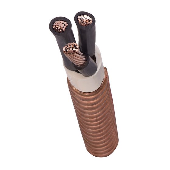
- Page 13 ® VITALink MC Transit 2-Hour Fire Rated Power Cable www.vitalinkcable.com Jacket Armor Conductor Low Smoke Zero Halogen (LSZH) Continuously welded and corrugated copper 90°C*, 600 Volt Annealed copper Class “B” strand NEC Type MC UL Listed UL Electrical Circuit Integrity System (FHIT 120) Insulation Inner Jacket Proprietary Fire-Roc™...
- Page 14 ® VITALink MC Transit 2 Hour Fire Rated Power Cable Consult factory for availability and minimum quantity requirements Nominal Core Nominal Armor Nominal Cable Approximate Size Number of Diameter Diameter Diameter over Outer Jacket Net Weight Product Code (AWG kcmil) Conductors (In) (In)
-
Page 15: Materials
Recommendations for fittings and other materi- The design should allow additions, replacements, and other changes to be made easily, at minimum als for use with VITALink MC are shown in cost, and with minimum interruption of service. Appendix 1. Other commercially available mate- rials may work as well. - Page 16 How To Handle Cable Reels Y E S Always load and store reels Upended heavy reels will often upright on their flanges be damaged. block securely. Reels can be hoisted with a Do not lift by a single reel flange. properly secured shaft extend- Cable or reel may be damaged.
- Page 17 should be handled utilizing equipment designed damage the cable surface by preventing the for that purpose. Reels of cable must not be reel flanges from bearing the total weight. dropped from any height, particularly from trucks Table 1 provides capacities of standard RSCC or other transporting equipment.
- Page 18 Table 1. VITALink MC* Length Capacities On Standard Shipping Reels Flange (Inches) Traverse (Inches) Drum (Inches) Tare Wt: (Lbs) Max. Net: (Lbs) 6,000 6,000 6,000 9,000 15,000 14,000 Maximum Diameter Reel Capacity In Feet 0.700 3,300 6,058 12,520 16,021 26,243 27,146 0.800...
-
Page 19: Pulling Calculations
4. Pulling Calculations When cables are pulled into raceways or trays, dependent upon the method of attachment to they are likely to be subjected to physical the cable, the allowable sidewall bearing pres- stresses that they will never again be required sure, and the construction of the cable. - Page 20 The maximum value for sidewall pressure applied. When pulling by gripping the conduc- depends on the cable design. For VITALink MC tors with a pulling eye or bolt, the maximum ten- it is normally 400 pounds per foot of bend, with sion is usually limited to 10,000 pounds.
- Page 21 Table 3. Maximum Tension Based On Copper Conductor Tensile Strength Limit Conductor Equivalent Size Circular Mil Area (AWG or Kcmil) (Kcmil) (Pounds) (Pounds) (Pounds) 4.11 – 6.53 – 10.38 – 16.51 – 26.24 – 41.74 – 1,002 1,336 52.62 – 1,263 1,684 66.36...
- Page 22 Table 4. Maximum Tension Based On SWP Limits For Various Sheave Diameters Maximum Tension Based On SWP Limit - T Sheave (Pounds) Inner Diameter (Inches) SWP = 400 Pounds/Foot SWP = 300 Pounds/Foot 1,000 1,083 When pulling multiple cables together, addi- tension based on sidewall pressure limits for tional forces may be encountered based on various sheave diameters.
- Page 23 Estimated Pulling Tension T = Tension coming bend in pounds The installer should calculate estimated pulling = Accumulated tension going into the bend tensions for all cables to be pulled, to insure that in pounds the allowable values established in the previous sections are not exceeded.
- Page 24 VITALink MC. For cases not shown please call distinct cases occur. There are bends which the RSCC Engin eering Depart ment. Note, bend...
- Page 25 Table 7. VITALink MC — Minimum Bend Radius Normal Min. Bend Radius (Inches) Product No. of Conductor Size Armor Diameter Code Conductors (AWG/Kcmil) Training Pulling (Inches) VM02014-100 0.78 VM03014-100 0.82 VM04014-100 0.89 VM02012-100 0.82 VM03012-100 0.89 VM04012-100 0.94 VM02010-100 0.89 VM03010-100 0.94...
- Page 26 Note, the sheave to minimize sidewall pressure constraints. diameter is 2 times the sheave radius (see Table 8. Minimum Effective Sheave Diameter Minimum Effective Sheave Diameter (Inches) Cable Diameter VITALink MC (Inches) 0.75 1.00 1.25 1.50 1.75 2.00...
- Page 27 Cable Sheave Radius Cable Figure 5. Single Sheave Effective Radius Cable Cable PROPER IMPROPER Figure 6. Typical Multiple Sheave Arrangement RSCC Wire & Cable LLC © 2015 • 20 Bradley Park Road • East Granby, CT 06026 • 800-327-7625 • 800-653-8300 • Fax: 860-653-8321 • www.vitalinkcable.com...
-
Page 28: Pre-Installation
5. Pre-Installation This section deals with factors that should be cantly damage or impair the operation or per- considered prior to installation. It is highly rec- formance of electrical cables. While different ommended that cable installations be pre- cable constructions may have varying degrees planned. - Page 29 Installation Equipment taken when working around energized cables and equipment. Any cable lubricant spilled on Where mechanical assistance is required, the floor should be cleaned up or covered pulling equipment of adequate capacity such as immediately. a winch that provides a steady continuous pull Cables should not be pulled around corners on the cable should be used.
- Page 30 where the tension is near zero, so that sidewall Cable should only be pulled into clean raceways pressure will be very low. If not properly utilized, or cable trays. Prior to installing cable, all debris these devices may cause damage. Therefore, should be removed.
- Page 31 • Pulling in the proper direction. Where practi- tion is performed which indicates the ten- sion to be well within allowable limits. cal, a cable pull should begin nearest the end having the greater degrees of bends and exit 2. Monitoring the actual tension applied using a the end having the least degrees of bends.
- Page 32 For VITALink MC, both the armor and leading section of the assembly should be conductors should be gripped simultaneously.
-
Page 33: Installation
UL System 120/ ULC S139 FHIT7 120 (4ft). General VITALink MC is installed and supported in much the same manner as other armored cables whether surface mounted, suspended, in cable tray or direct buried. The requirements of... - Page 34 Paralleling installation and work back toward the reel, straightening as you go. Straighten by hand if Conductors to be joined in parallel should be possible, do not use tools such as a hammer or 1/0 AWG or larger. See NEC Article 310.10(H) screwdriver, since this may deform the armor.
- Page 35 to the pull rope and/or the conductor in order to are designated for use in a specific system(s) prevent relative movement of the conductors for which corresponding ratings have been and armor. Utilize supplementary pulling lines developed and are not intended to be inter- with luffing grips as applicable.
- Page 36 Installation in Raceways Installation In Cable Trays Installations in raceways need special consider- When hand feeding (laying) cable in trays and ations, so please consult the RSCC Engineering trenches having open tops or removable covers, Department. it is recommended that: •...
- Page 37 Cables should be placed neatly, and orderly across the full width of the tray to maintain a VITALink MC may be installed in conduit in con- uniform level. The cable should be properly crete or earth. Refer to the section on installa- spaced for ampacity concerns.
-
Page 38: Post Installation
A sufficient length of cable should be removed d) Splice VITALink MC to the wire using an ap - from the pulling end to ensure that an adequate proved method. Note a transition splice may length of undamaged cable is available for ter- be required based on ampacity considerations. - Page 39 Cable Terminating • Generally, a seal should not be applied around the connector. Contact the RSCC Engineering General procedures for terminating are provided Department for further information. below. Be advised that RSCC cannot be respon- • Strip the insulation from each conductor for a sible for the effectiveness of a termination or distance equal to the depth of the terminal lug splice because we have no control over the...
- Page 40 Table 11. Box Size per NEC 314.28 Minimum Box Length for Straight Through Splice Conduit Conduit AWG/Kcmil Size Size AWG/Kcmil Size Size 1.25 1.25 1.25 1.25 1.25 Minimum Box Size for Angle Splice Conduit Conduit AWG/Kcmil Size Size AWG/Kcmil Size Size 1.25 1.25...
- Page 41 Jacket Removal (when provided) To remove the outer jacket: 1. Measure the length of jacket to be removed and mark. With a sharp knife score around the jacket to about half its thickness. Do not score the armor. (Figure 11) Figure 11 2.
- Page 42 Armor Removal 1. Mark where the armor is to be cut by wrap- ping tape around the cable as a guide. Use a tubing cutter to cut the armor. The cutting wheel should be adjusted at the crest of a corrugation and rolled back and forth in ever increasing arcs while advancing the wheel until a 360 degree turn can be made without...
- Page 43 Inner Jacket Removal 1. Mark where jacket is to be cut by wrapping tape around the cable as a guide. Use a knife to longitudinally cut back inner jacket appropriate distance. Leave inner jacket on where possible for additional protection. An adequate length of free conductor should be provided per NEC/CEC.
- Page 44 Please call the RSCC Engineering Depart ment for additional informa- tion and to request the following publications in pdf format: • VITALink MC Taped Splice Kit — Pig Tail Crimp • VITALink MC Two-Way Taped Splice Kit Cable Test...
-
Page 45: Glossary Of Terms
8. Glossary of Terms Ampacity - The current, in amperes, that a Fire-Roc™ - RSCC trade name for a proprietary conductor can carry continuously under the insulation capable of passing the UL 2 hour fire conditions of use without exceeding its tem- test as part of a qualified system. - Page 46 600 volts. Pull Rope - A high strength line which is VITALink MC attached to the cable to allow it to be pulled. - RSCC trade name for a con- ®...
-
Page 47: References
9. References AEIC G5, “Underground Extruded Power Cable IEEE 518, “Guide for the Installation of Electrical Pulling Guide”. Equipment to Minimize Electrical Noise Inputs to Controllers from External Sources”. ANSI/NFPA 70, “National Electrical Code”. IEEE 525, “IEEE Guide for the Design and Installation of Cable Systems in Substations”. - Page 48 10. Appendix 1 A list of MC connector manufacturers for outside of the fire zone: Company Name Series Cooper Crouse-Hinds Hawke Cable Glands America N701 Hubbell Killark Electric Thomas & Betts Corporation NOTE: For MC connector in the fire zone, see UL FHIT 120/ULC S139 FHIT7 120. Information provided is believed to be accurate, but company should be contacted for information on products and use.
- Page 49 Notes: RSCC Wire & Cable LLC © 2015 • 20 Bradley Park Road • East Granby, CT 06026 • 800-327-7625 • 800-653-8300 • Fax: 860-653-8321 • www.vitalinkcable.com...
- Page 51 RSCC Wire & Cable LLC 800-327-7625 • Tel: 860-653-8300 • Fax: 860-653-8301 www.r-scc.com ISO 9001/QS 9000 REGISTERED East Granby, CT 20 Bradley Park Road East Granby, CT 06026 Tel: 860-653-8300 Fax: 860-653-8301 800-327-7625 © 2015 RSCC Wire & Cable LLC RSCC VIT-MC-04 (May 2015)
Need help?
Do you have a question about the VITALink MC and is the answer not in the manual?
Questions and answers