
Subscribe to Our Youtube Channel
Summary of Contents for Environnement MP101M
- Page 1 TECHNICAL MANUAL MP101M SUSPENDED PARTICULATE BETA GAUGE MONITOR - APRIL 2014 - 111 bd Robespierre, 78300 POISSY - -TEL. 33(0)-1.39.22.38.00 – FAX 33(0)-1.39 65.38.08 http://www.environnement-sa.com...
- Page 2 Unless otherwise stipulated, the warranty period shall have a duration of twelve months from the date of delivery within the meaning of article 6 paragraph 2 of the «ENVIRONNEMENT S.A: 2013 INTERNATIONAL GENERAL TERMS AND CONDITIONS OF SALES», even if the shipment or assembly is postponed for any reason outside the seller's control.
-
Page 3: Table Of Contents
2–8 2.4. ORGANIZATION OF MEASUREMENTS 2–8 2.5. REGULATED SAMPLING TUBE (RST) 2–11 CHAPTER 3 OPERATION INITIAL START-UP 3–4 PROGRAMMING THE MP101M 3–7 DESCRIPTION OF THE DIFFERENT SCREENS 3–10 CHAPTER 4 PREVENTIVE MAINTENANCE 4.1. SAFETY INSTRUCTIONS 4–2 4.2. MAINTENANCE CALENDAR 4–3 4.3. - Page 4 MP101M Environnement Duplication prohibited CHAPTER 5 CORRECTIVE MAINTENANCE 5.1. LIST OF FAULTS AND CORRECTIVE ACTIONS 5–4 5.2. MODULE BOARD OF MP101M 5–8 5.3. GENERAL CONNECTION DIAGRAM 5–9 CHAPTER 6 APPENDIX LIST OF FIGURES Table 3–1 – DB25 Connections 3–3 Table 3–2 – MUX signals (Acceptable limits on channel 1 to 16 of the multiplexer) 3–46...
- Page 5 Figure 0–2 – Source dimensions (in mm) 0–12 Figure 0–3 – Radioactive clover 0–15 Figure 0–4 – Signaling label 0–16 Figure 1–1 – MP101M presentation 1–2 Figure 1–2 – Keyboard and display 1–4 Figure 1–3 – Front face with the door closed 1–5 Figure 1–4 –...
- Page 6 MP101M Environnement Duplication prohibited INDEX OF PAGES Page Date Page Date Page Date 04.2014 09.2013 3-41 09.2013 09.2013 09.2013 3-42 09.2013 09.2013 09.2013 3-43 09.2013 09.2013 09.2013 3-44 09.2013 09.2013 09.2013 3-45 09.2013 04.2014 2-10 09.2013 3-46 09.2013 09.2013 2-11 09.2013...
- Page 7 MP101M Environnement Duplication prohibited Page Date Page Date 4-25 09.2013 4-26 09.2013 4-27 09.2013 4-28 09.2013 09.2013 09.2013 09.2013 09.2013 09.2013 09.2013 09.2013 09.2013 09.2013 5-10 09.2013 09.2013 09.2013 SEPTEMBER 2013 0–7...
- Page 8 MP101M Environnement Duplication prohibited Page intentionally blank SEPTEMBER 2013 0–8...
-
Page 9: Safety Guidelines
MP101M Environnement Duplication prohibited SAFETY GUIDELINES THIS CHAPTER REFERS TO FRENCH REGULATIONS AND IS INCLUDED SOLELY FOR THE PURPOSE OF EXAMPLE AND INFORMATION. FOR OPERATION OF THE ANALYZER OUTSIDE FRENCH TERRITORY, PLEASE REFER TO THE REGULATIONS IN FORCE FOR RADIATION PROTECTION IN THE COUNTRY IN WHICH IT IS TO BE USED. -
Page 10: Reminder Of Principal Statutory Technical Precautions
When the sealed source is definitively removed from service, the end-used have to yield the source to an authorized organism in his country. If there is no this kind of organism who deals with radioactives wastes, radioactive source shall be return to ENVIRONNEMENT SA, after receive the written agreements from ENVIRONNEMENT SA. -
Page 11: Presentation Of Equipment
MP101M Environnement Duplication prohibited SAFETY GUIDELINES PRESENTATION OF EQUIPMENT 0.3.1 DESCRIPTION The source is secured in the rotary cylinder which is integrated in the upper block of the Beta gauge. Figure 0–1 – Beta gauge source holder A warning label is placed on the front side of the upper block of the receiver. -
Page 12: Figure 0-2 - Source Dimensions (In Mm)
MP101M Environnement Duplication prohibited SAFETY GUIDELINES 0.3.3 A RADIOACTIVE SOURCE Radio-element Carbon 14 Sealed, Shape classified C34343 under ISO2919 standards Activity 1,6MBq+/-15%, means 1,84MBq maximum Type - energy : 0,160 MeV Emission Period of the radioelement 5730 years Ø 22 Ø... -
Page 13: Risks Assessments
MP101M Environnement Duplication prohibited SAFETY GUIDELINES RISKS ASSESSMENTS Measurements of dose rate were taken by the IRSN, French expert of radioprotection. The intensity of emission flow is the same one for each type of source used in the analyzers of particles. -
Page 14: Risk Analyses
In normal use, the personnel, using MP101M, is not defined as exposed worker, and is not classified into category A or B. The acceptable exposure values are those valid for the public. -
Page 15: Radiation Protection Recommendations
MP101M Environnement Duplication prohibited SAFETY GUIDELINES RADIATION PROTECTION RECOMMENDATIONS 0.6.1 SIGNALS A label indicating the presence of a radioactive source can be put outside on the analyzer door. In this case, it is necessary to use the black radioactive clover on yellow background. To take care not to use other types of clover. -
Page 16: Safety Instructions - Example
MP101M Environnement Duplication prohibited SAFETY GUIDELINES SAFETY INSTRUCTIONS - EXAMPLE SAFETY INSTRUCTIONS This analyzer contains a radioactive source of Carbon-14, activity 1.6 MBq+/-15% THE EMISSION HEAD containing the source is sealed by special screws The presence of source is indicated by the following label : Figure 0–4 –... -
Page 17: Technical Controls Of Radioprotection
Duplication prohibited SAFETY GUIDELINES TECHNICAL CONTROLS OF RADIOPROTECTION Environnement SA recommends to the users of the analyzers containing a radioactive source, to periodically carry out the technical checking of radioprotection, in particular : Monthly checks, using, for instance, the Contamination Test described in the 4.3.10 sheet of chapter 4 of the technical manual of the analyzer. - Page 18 MP101M Environnement Duplication prohibited Page intentionally left blank SEPTEMBER 2013 0–18...
-
Page 19: General - Characteristics
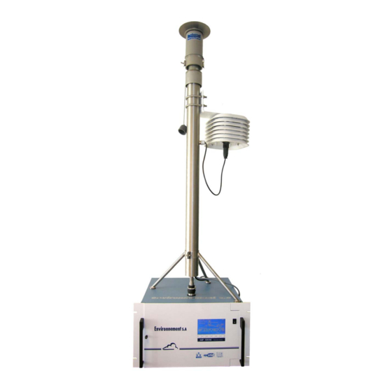
1–23 1.2.5.2. PM USEPA designation 1–23 1.2.5.3. EN12341 designation 1–24 Figure 1–1 – MP101M presentation 1–2 Figure 1–2 – Keyboard and display 1–4 Figure 1–3 – Front face with the door closed 1–5 Figure 1–4 – Front face, overview of collector assembly and beta gauge 1–7... - Page 20 MP101M Environnement Duplication prohibited GENERAL – CHARACTERISTICS Figure 1–1 – MP101M presentation SEPTEMBER 2013 1–2...
- Page 21 GENERAL 1.1.1. PRESENTATION (FIGURE 1–1) The MP101M system is used to measure suspended particulate matter in the ambient air. Sampled air can also be monitored continuously for possible natural radioactivity, with programmed alarm in the event of a threshold overshoot.
- Page 22 MP101M Environnement Duplication prohibited 1.1.2. DESCRIPTION 1.1.2.1. Front face Refer to Figure 1–2 and Figure 1–3. The front panel of the analyzer is formed by a fixed part and a hinged door giving access to the collector and Beta gauge assembly.
- Page 23 MP101M Environnement Duplication prohibited Figure 1–3 – Front face with the door closed SEPTEMBER 2013 1–5...
- Page 24 MP101M Environnement Duplication prohibited Door open (Figure 1–4) : The door is opened by turning the locking knob clockwise. The following components are then accessible : – The reference gauge (1) The reference gauge is located in a specific housing protected from dust.
- Page 25 MP101M Environnement Duplication prohibited (1) reference gauge, (3) source holder, (4) flexible channel, (5) capstan, (6) disengageable pinch roller, (7) take-up reel, (8) Geiger-Müller tube detector, (9) pressure assembly, (10) pay-out reel. Figure 1–4 – Front face, overview of collector assembly and beta gauge SEPTEMBER 2013 1–7...
- Page 26 Rear panel Refer to Figure 1–5. The rear panel of the MP101M contains the electrical connectors and the air outlet connector. It is designed as a drawer containing various mechanical elements on its internal part. – Air outlet (bottom-left side) ...
- Page 27 MP101M Environnement Duplication prohibited Rear panel drawer. On its inner face, the rear panel is designed as a drawer for receiving various mechanical parts (refer to Figure 1–6) : The axis of pay-out reel (1), The axis of take-up reel (2), ...
- Page 28 MP101M Environnement Duplication prohibited 1.1.2.3. Components location Refer to Figure 1–7. The components inside the unit are accessed by simply unscrewing the knurled knobs (Rep. 9, Figure 1–5) at the rear of the unit and removing the upper cover. The housing is divided into three parts, separated by two aluminium plates: ...
- Page 29 MP101M Environnement Duplication prohibited – Details of the Flow regulation part (Figure 1–8) The main components are: one motor-driven valve (1), a block with a 2.8 mm diameter flat orifice (3). The hydrostatic pressure drop observed on passage at the throttle in the fluid circuit is used to deduce the velocity of flow and the flow rate.
- Page 30 MP101M Environnement Duplication prohibited 1.1.3. ASSOCIATED EQUIPMENT – Sampling assembly, – Pump assembly, – Recorders, PC (optional) 1.1.3.1. Sampling assembly See section 1.2.5. It consists of : – A standard sampling head, interchangeable according to application : TSP, PM10 US EPA* or EN12341 ...
- Page 31 MP101M Environnement Duplication prohibited 1.2. CHARACTERISTICS 1.2.1. TECHNICAL CHARACTERISTICS Measurement principle Cyclic measurement by Beta rays gauge Type of measurement and units – Density deposited in µg/cm – Concentration in µg/m Units of flow l/mn, m Units of volume litres, m...
- Page 32 MP101M Environnement Duplication prohibited Concentration measurement range on one period: Minimum detectable concentration Duration of scan period in µg/m on one period in hours /h flow rate Concentration measurement range on one cycle : Minimum detectable concentration Duration of cycle in hours in µg/m...
- Page 33 MP101M Environnement Duplication prohibited Output signals up to 8 analog outputs (programmable full scale ) 0-1 V, 0-10 V, 0-20 mA, or 4-20 mA with galvanic isolator on option (depending on the number of ESTEL boards option present) Power supply...
- Page 34 MP101M Environnement Duplication prohibited 1.2.4. INSTALLATION CHARACTERISTICS The MP101M monitor can be integrated in a standard cabinet for installation indoors or in a sealed enclosure for use outdoors. 1.2.4.1. Composition MP101M standard cabinet This is a standard 19-inch cabinet designed to receive 32 "deep" units (useful depth = 750 mm).
- Page 35 Installing the MP101M The MP101M is set on the aluminium base plate and blocked by inserting the studs of the rear legs into the holes provided for this purpose on the mounting plate. SEPTEMBER 2013...
- Page 36 Installing the regulated sampling tube (RST) Place the sampling head in its housing and adjust the height to ensure tightness between the head channel and the channel of the MP101M, without crushing it (see diagram below). Sampling head Gasket of tightness...
- Page 37 MP101M Environnement Duplication prohibited Figure 1–10 – Regulated sampling tube (RST) Fasten the meterological sensors on the external part of the sampling tube and connect the head heating to the socket marked “tube heating” on the rear panel. Connect the 15 points connector to the socket marked “TIMH sensor”...
- Page 38 It is highly recommended to provide a system for securing the head in position to prevent it from moving downward and bearing on the MP101M box. In all cases, the head must remain easily removable for maintenance purposes, for example.
- Page 39 It is absolutely necessary to refer to Chapter 0, Safety Guidelines section, pages 0-10 to 0-18, relative to equipment implementing radioactive sources. The MP101M monitor must be handled with care to avoid damage to the various connectors and fittings on the rear panel.
- Page 40 MP101M Environnement Duplication prohibited Figure 1–12 – Outline dimensions SEPTEMBER 2013 1–22...
- Page 41 1.2.5.1. USEPA designation The PM automatic analyzer of particles, MP101M model, is nominated USEPA equivalent method as defined by the code of federal laws CFR 40, Part 53, when it operates under the following conditions: 1. Use of a sampling head specified in the 40 CFR 50, appendix L paragraph 7.3.2** and 7.3.4.4*** or in the previous model “flat-topped 246b”.
- Page 42 1.2.5.3. EN12341 designation The PM automatic analyzer of particles, MP101M model, is certified EN12341, when it operates under the following conditions : 1. Use of a sampling head equipped with a fractionation (screening) device equivalent to the EN12341, and with a reference tube RST*100, RST*150 or RST* 200 consisting of a temperature and humidity sensor.
-
Page 43: Principle Of Operation
MP101M Environnement Duplication prohibited CHAPTER 2 PRINCIPLE OF OPERATION 2.1. BETA GAUGE PRINCIPLE (FIGURE 2–1 AND FIGURE 2–2) 2–3 2.2. FLOW REGULATION PRINCIPLE 2–6 2.3. ACQUISITION AND PROCESSING OF MEASUREMENT PARAMETERS 2–8 2.4. ORGANIZATION OF MEASUREMENTS 2–8 2.5. REGULATED SAMPLING TUBE (RST) 2–11... - Page 44 MP101M Environnement Duplication prohibited PRINCIPLE OF OPERATION Sampling head Sample tube Filter Emiter unit Beta gauge Receiver unit Vacuum pump Flow regulation device Figure 2–1 – General functional diagram SEPTEMBER 2013 2–2...
-
Page 45: Beta Gauge Principle (Figure 2-1 And Figure 2-2)
MP101M Environnement Duplication prohibited 2.1. BETA GAUGE PRINCIPLE (FIGURE 2–1 AND FIGURE 2–2) A BETA gauge consists of a radioactive source of Carbon 14 ( C) radioelement, emitting soft Beta radiation and a radioactive radiation detector: Geiger-Müller (G.M.) tube. The G.M. is mounted at a given distance downstream of the filter ribbon which gathers the particles suspended in the air. - Page 46 MP101M Environnement Duplication prohibited The measurement method is governed by the following relations: a) Blank filter at start of cycle e -k (m Count without absorbent (see Remark) Corrected count, in counts per second, on blank filter (air + filter) (see NOTE)
- Page 47 MP101M Environnement Duplication prohibited m Density of particles deposited. Density of air (mg/cm ) at temperature of T In the two relations a) and b), this gives: k ( m + m 2 - m 1 ) and: ...
-
Page 48: Flow Regulation Principle
MP101M Environnement Duplication prohibited 2.2. FLOW REGULATION PRINCIPLE The sample is taken at a constant volume flow rate with compensation of load loss due to the filter and progressive depositing of dust. The flow rate is therefore controlled and maintained at the selected reference value of 1.0 m... - Page 49 MP101M Environnement Duplication prohibited The internal sensors of temperature and pressure coupled with the meterological sensors of regulated sampling tube (RST) line enable to measure the “volumetric” flow rate in the atmospheric conditions: The flow rate is thus controlled and maintained constant to the nominal setting value (1 m /h) at level of sampling head.
-
Page 50: Acquisition And Processing Of Measurement Parameters
MP101M Environnement Duplication prohibited 2.3. ACQUISITION AND PROCESSING OF MEASUREMENT PARAMETERS The temperature and pressure sensor outputs are transmitted via an analog multiplexer with 16 input channels to the D/A converter on the Module board (4) in figure 1–7. The signals are converted into digital signals and sent to the microprocessor. - Page 51 The average concentration is calculated as follow : If the MP101M is configured to operate in cycles and periods, it is possible to display on the screen (as additional information), the value of the cumulated concentration at the end of every scanning period.
- Page 52 MP101M Environnement Duplication prohibited at the end of the next period, the cumulated concentration is given by : at the end of the cycle, the cumulated concentration is given by : ...
-
Page 53: Regulated Sampling Tube (Rst)
MP101M Environnement Duplication prohibited NOTE : The concept of dew point is an important basis concept about the operation of cooling dryers of compressed air. Calculation methods : Magnus-Tetens Formula Field of validity: T : measured temperature : 0° C < T < 60 °C*0.15 ... - Page 54 MP101M Environnement Duplication prohibited Figure 2–5 – Regulated sampling tube (RST) line assembly SEPTEMBER 2013 2–12...
- Page 55 MP101M Environnement Duplication prohibited The sampling temperature control is managed by the software of the device in the following way: Sampling is carried out at atmospheric temperature. A continuous measurement of external relative humidity is carried out, ...
- Page 56 MP101M Environnement Duplication prohibited This page is intentionally left blank SEPTEMBER 2013 2–14...
-
Page 57: Operation
OPERATION INITIAL START-UP 3–4 3.1.1 PRELIMINARY OPERATIONS (FIGURE 3–1) 3–4 3.1.2 STARTING UP THE UNIT 3–5 PROGRAMMING THE MP101M 3–7 3.2.1 SELECTION AND MODIFICATION OF PROGRAMMABLE PARAMETERS 3–7 3.2.1.1 Screen areas definition 3–7 3.2.1.2 Definition of main functions of the keyboard 3–8... -
Page 58: Figure 3-1 - Fluids And Electric Connection
MP101M Environnement Duplication prohibited TESTS Arm7 inputs - outputs 3.3.6.2 3–47 TESTS Mother board inputs - outputs 3.3.6.3 3–48 TESTS Gauge test 3.3.6.4 3–52 TESTS Mass test 3.3.6.5 3–55 3.3.7 I2C CARD(S) 3–59 I2C CARD(S) Estel card(s) 3.3.7.1... - Page 59 MP101M Environnement Duplication prohibited OPERATION The information given in Table 3-1 is necessary for the user to install the unit. It identifies the connection points necessary for correct operation of the serial communication. Table 3-1 – DB37 and DB25 connector links...
-
Page 60: Initial Start-Up
MP101M Environnement Duplication prohibited INITIAL START-UP The monitor is checked and calibrated in factory before delivery. 3.1.1 PRELIMINARY OPERATIONS (FIGURE 3–1) Start-up first consists in carrying out the following preliminary operations: Visually examine the interior of the instrument to ensure that no component has been damaged during transport. - Page 61 MP101M Environnement Duplication prohibited 3.1.2 STARTING UP THE UNIT Carry out, in the following order, the INSTALLATION / STARTING UP procedure described below : 1/ Press down the ON/OFF push-button located on the front panel to start the unit. The synoptic screen is displayed and the instrument passes into the "WARM-UP"...
- Page 62 MP101M Environnement Duplication prohibited Then adjust the value of Head temperature: it must be equal to : The Atmos. temperature, if the Relative humidity is lower than 60%, The Atmos. temperature, + 5°C, if the RH relative humidity is higher than 60%.
-
Page 63: Programming The Mp101M
MP101M Environnement Duplication prohibited PROGRAMMING THE MP101M 3.2.1 SELECTION AND MODIFICATION OF PROGRAMMABLE PARAMETERS The keyboard is located under the LCD screen. The bottom line gives the function of each key for the current screen. The title of the menus and the selected fields are displayed in reverse video. By default, the first line of the menus is selected. - Page 64 MP101M Environnement Duplication prohibited 3.2.1.2 Definition of main functions of the keyboard The availability of these functions is context dependent. Used to display the previous menu or to abort the current operation (parameter programming, [] etc.) Used to select the required sub-menu and the parameter to be modified. It is also used to []...
- Page 65 MP101M Environnement Duplication prohibited The diagram of menu and sub-menu tree of the software is given in the Figure 3–2. MAIN MENU I2C CARD(S) EASUREMENT ALIBRATION TORED DATA ESTS ONFIGURATION Date/time/ Tabular MUX signals ESTEL card(s) Instantaneous Beta gauge Language...
-
Page 66: Description Of The Different Screens
MP101M Environnement Duplication prohibited DESCRIPTION OF THE DIFFERENT SCREENS 3.3.1 MAIN MENU This screen is used to select the menus giving access to the analyzer operating parameters. Select the menu with the [] or [] keys, validate the selection with the [ ] key. - Page 67 MP101M Environnement Duplication prohibited 3.3.2 MEASUREMENT This screen enables the user to select the measurement display mode: instantaneous, average, synoptic or graphic, to display the alarms and to check the status of the current cycle. SEPTEMBER 2013 3–11...
- Page 68 MP101M Environnement Duplication prohibited MEASUREMENT Instantaneous 3.3.2.1 This screen displays the instantaneous values of the programmed measurement parameters. It is possible to visualize three channels per page displayed. To access the next channels, it is necessary to press down the [>>] key and display the next page.
- Page 69 MP101M Environnement Duplication prohibited MEASUREMENT Average 3.3.2.2 This screen displays the averages of the instantaneous values of the programmed measurement parameters. Definition of keys specific to this screen: For this screen, the [Start], [Stop] and [>>] keys have the same functions as for the ...
- Page 70 MP101M Environnement Duplication prohibited MEASUREMENT Synoptic 3.3.2.3 This screen represents the physical measurement components of the instrument and displays the measurement channels values of the operation parameters. The [Start] key enables to start the cycles programmed in the « CONFIGURATION Measurement mode »...
- Page 71 MP101M Environnement Duplication prohibited Description of the sequence chain when the system starts up ([Start] key): 1 – the pressure panel goes down. 2 – the filter paper is fed for a distance equivalent to one step, and is put in place under the filter- holder.
- Page 72 MP101M Environnement Duplication prohibited MEASUREMENT Graphic 3.3.2.4 This screen is used to adjust the parameter for graphic plot of measurement channel values: it enables the user to define: The measurement channel to display. The max. and min. display scales.
- Page 73 MP101M Environnement Duplication prohibited MEASUREMENT Alarm display 3.3.2.5 This screen displays operation faults in case of alarm. The type of alarm is indicated on the left side of the display, followed by its value. In the other columns are displayed the minimum and maximum threshold values related to the parameter which triggered the alarm, and its measurement unit.
- Page 74 MP101M Environnement Duplication prohibited MEASUREMENT Current cycle 3.3.2.6 This screen is used to visualize the status of the current cycle and period as well as the date and time to start the next cycle. Date and time field indicates the present date and hour.
- Page 75 MP101M Environnement Duplication prohibited 3.3.3 CALIBRATION This menu is used to access calibration of Beta gauge and sampling flow rate. NOTE : The « Beta gauge » sub-menu is not displayed when the analyzer is in Measurement mode. SEPTEMBER 2013...
- Page 76 MP101M Environnement Duplication prohibited CALIBRATION Beta gauge 3.3.3.1 The screen shown below displays: the Beta calibration coefficient (K) determined during the previous calibration, the value of the reference gauge used for the calibration, the number of consecutive calibrations necessary to obtain a calibration value, ...
- Page 77 MP101M Environnement Duplication prohibited Press down the [Start] key to launch the calibration. > This screen is used to monitor the phases sequence using the « » cursor. The instrument enters into the « Initialization » phase, the filter paper is fed for one step, and the pressure plate is placed into high position, against the filter paper.
- Page 78 MP101M Environnement Duplication prohibited The « 1/10 » ratio indicates that the instrument carries out the first blank of a 10 calibrations series. The instrument will repeat 10 times the blank measurement, as programmed in the Calibration number field. Between each « Blank », the GM counter is switched off.
- Page 79 MP101M Environnement Duplication prohibited The instrument checks the reference gauge, then the cursor moves to « Calibration » and the instrument starts the calibration. In the next field, the instantaneous value of counting is displayed on the left, and the average value of counting is displayed on the right.
- Page 80 MP101M Environnement Duplication prohibited It gives the summary of the last calibration with : The number of calibration cycles performed, the counting duration for each cycle, the value of the reference gauge, stated into µg/cm The average values of blanks and calibrations with the average of their respective measurement temperatures.
- Page 81 MP101M Environnement Duplication prohibited Press down the [<<<] key to return to the previous screen, and press down the [Spans] key to display the screen shown below: This screen displays : The detail of measurements carried out on the reference gauge with the value of filter temperature for each measurement, ...
- Page 82 MP101M Environnement Duplication prohibited CALIBRATION Linearizations 3.3.3.2 This screen enables the user to linearize the measurements of periodic, cyclic and average concentration, when using another analyzer as reference…(reference defined according to the standards EN12341, EN14907, or USEPA). Parameters for the EPA designated instruments are set at the factory and should NOT be changed by the user since it would affect the validity of the measurements.
- Page 83 MP101M Environnement Duplication prohibited CALIBRATION Flow rate 3.3.3.3 This screen indicates the flow rate F coefficient of the instrument, the calibration method, to be selected between « Flow meter » or « Gas meter », and the previous calibration date with the indicated method.
- Page 84 MP101M Environnement Duplication prohibited This screen displays date and hour of the last calibration, the pressure and temperature values to which flow-rate was calibrated, and flow-rate parameters with the calculated values of the new F coefficient. Pressures fields : ...
- Page 85 MP101M Environnement Duplication prohibited Press down the [Start] key to start the calibration. This screen enables the user to monitor the phases sequence with the « > » cursor : the device enters into « Initialization » phase, the filter paper is fed for one step, and the pressure plate is placed in the up position, against the filter paper.
- Page 86 MP101M Environnement Duplication prohibited Pressure fields : P1 field: pressure value upstream the critical orifice, P2 field: pressure value downstream the critical orifice, Atm. field: atmospheric pressure. Temperature fields : Filter field : temperature at filter level, ...
- Page 87 MP101M Environnement Duplication prohibited If the span flow rate does not correspond to the flow rate measured by the instrument (difference > 1,5 l/min), repeat the calibration procedure. Quit the display by pressing down the [] key, then the [Stop] key.
- Page 88 MP101M Environnement Duplication prohibited CALIBRATION Pressures 3.3.3.4 This screen enables the user to calibrate the values of the three pressure sensors : Upstream pressure, Downstream pressure, Atmospheric pressure. Using a reference sensor (barometric), adjust the A and B values for the three sensors using the [], [], [] keys.
- Page 89 MP101M Environnement Duplication prohibited 3.3.4 CONFIGURATION This menu gives access to the following functions: Response time programming. Analog output configuration. Unit modification and offset adjustment. Alarm thresholds programming, and activation and assignment of alarm relays. ...
- Page 90 MP101M Environnement Duplication prohibited CONFIGURATION Measurement mode 3.3.4.2 This screen allows the user to program: The sampling cycle duration, configurable from 1h to 96 hours : the standard value is 24 hours. The measurement period during each cycle, configurable from 10 minutes to 48 hours : the US EPA standard value is 1 hour.
- Page 91 MP101M Environnement Duplication prohibited Start type fields: the [] key is used to select one of the 3 possible choices: Immediate: by pressing down the [Start] key in the « MEASUREMENT Instantaneous » and « MEASUREMENT Synoptic »...
- Page 92 MP101M Environnement Duplication prohibited Press down the [>] key to display the next screen. Contamination test field : if this field is activated (ON position), the analyzer will check the radioactive contamination at the end of each measurement cycle. This checking will be carried out with the Geiger counter, without using the radioactive source.
- Page 93 MP101M Environnement Duplication prohibited Maintenance field: when this field is ON, it enables the user to trigger one of the alarm relays. Light screen Off delay field allows the user to program the time delay after which, without any action on keyboard, the screen passes to stand-by mode.
- Page 94 MP101M Environnement Duplication prohibited CONFIGURATION Offsets / Units / Conversions 3.3.4.4 This screen is used to program the offset on the eight channels available in this screen : this value is added to the measurements value. It is also used to program the measurement unit, as for the conversion coefficients: CONFIGURATION ...
- Page 95 Communication protocol: Mode 4,JBUS, PRN. Mode4 is a communication protocol proper to Environnement SA, designed to send and receive data. It works according to master/slave mode. JBUS protocol is an industrial protocol designed to dialog with automatons. It works according to master/slave mode.
- Page 96 MP101M Environnement Duplication prohibited CONFIGURATION Communication Network configuration 3.3.4.7 To establish the communication between a local network and the analyzer it is necessary to configure an IP (Internet Protocol) address and a subnet mask that can be recognized by this analyzer.
- Page 97 MP101M Environnement Duplication prohibited CONFIGURATION Communication UDP server 3.3.4.8 UDP stands for User Datagram Protocol. The analyzer network communication runs only under this protocol. UDP applications use datagram sockets to establish host-to-host communications. These sockets bind the application to service ports that function as the endpoints of the data transmission.
- Page 98 MP101M Environnement Duplication prohibited 3.3.5 STORED DATA Stored data are accessed and managed directly from the Main menu. They are the average of analyzer measurements within a defined time interval. This screen allows the parameter « Data recording period » to be set from 1 to 1440 min (i.e., 24 hours).
- Page 99 MP101M Environnement Duplication prohibited Editing stored data in tabular form: This screen shows the list of stored data according to parameters defined in the previous screen. The running mode (measurement, zero, calibration, etc.) during a data storage period is coded in the status column.
- Page 100 MP101M Environnement Duplication prohibited Editing stored data in histogram form This screen displays records in columns, with each column corresponding to the average measurements within the data-recording period as defined in the « STORED DATA » screen. Only one channel is displayed at a time. The information line gives the date and hour of the first record, the channel name, the full scale with unit and the data recording period (alternately blinking).
- Page 101 MP101M Environnement Duplication prohibited 3.3.6 TESTS This screen gives access to the following sub-menus: Parameters checking for maintenance operation. Manual control of various elements. Mother board control. Arm7 board control. NOTE : In this screen, the « Gauge test » and « Mass test » items are not displayed when the analyzer is making measurements.
- Page 102 MP101M Environnement Duplication prohibited Table 3-2 – Multiplexer (MUX) signals (Acceptable limits on channel 1 to 16 of the multiplexer) Chan Abbreviations Parameters Lower Normal Upper limit (Displays) limit Ground - 50 mV 0 mV + 50 mV + 5 V...
- Page 103 MP101M Environnement Duplication prohibited TESTS Arm7 inputs - outputs 3.3.6.2 When this menu is available, no backup of output modification is carried out. This menu displays the status of the switches on the DNP-Arm7 board. It enables testing of the ON/OFF switch of the Back light of the LCD.
- Page 104 MP101M Environnement Duplication prohibited TESTS Mother board inputs - outputs 3.3.6.3 This screen is used to test the analog inputs/outputs of the mother board: Correct operation of the motor. Pump and Geiger counter controls. 3.3.6.3.1 Motor for moving on filter ribbon : To parameter the motor for moving on filter ribbon, proceed in the order : ...
- Page 105 MP101M Environnement Duplication prohibited Mark out the filter paper with a pen line to indicate the right side of the nozzle. Press down the [s] key again to restart the motor : after the motor stop, mark out the filter paper with a second pen line to indicate the right side of the nozzle.
- Page 106 MP101M Environnement Duplication prohibited 3.3.6.3.3 Moving plate motor: Using the [] [] keys, go to the Plate field of screen (1). On the last line of screen (1), press down the [Test] key : the screen shown below is displayed : ...
- Page 107 MP101M Environnement Duplication prohibited 3.3.6.3.4 Valve motor : Using the [] [] keys, go to the Valve field of screen (1). On the last line of screen (1), press down the [Test] key : the « Valve » screen is displayed.
- Page 108 MP101M Environnement Duplication prohibited TESTS Gauge test 3.3.6.4 This sub menu enables one to check the measurement stability of the Beta Gauge. This gauge test consists in checking the zero of the system by carrying out a series of « blank » measurements on the same part of filter paper, then to calculate the standard deviation of this measurement series.
- Page 109 MP101M Environnement Duplication prohibited When the cursor indicates « Start », press down the [Start] key to launch the Gauge test. The analyzer carries out an initialization by moving ahead a new part of filter paper towards the measurement position. Then, it controls the pump switching-on which will operate during 120 seconds in order to dry the filter paper.
- Page 110 MP101M Environnement Duplication prohibited This screen displays the report of the last gauge test performed. It indicates the number of measurement cycles done, the countings duration, the blank value of start, the average obtained for the n countings, the dust measurement and the standard deviation of this measurement, stated in µg/cm...
- Page 111 MP101M Environnement Duplication prohibited TESTS Mass test 3.3.6.5 This sub menu enables one to check the mass measurement stability of a reference gauge. The purpose of the test is to calculate the measurement accuracy and repeatability for a reference gauge whose density was predefined.
- Page 112 MP101M Environnement Duplication prohibited When the cursor indicates « Start », press down the [Start] key to launch a mass test. The screen shown above is replaced by this one : The analyzer carries out an initialization by moving ahead a new part of filter paper towards the measurement position.
- Page 113 MP101M Environnement Duplication prohibited Figure 3–4 – Putting in place the reference gauge Then the analyzer carries out the number of mass measurements programmed (10 in this screen) on the reference gauge. When these 10 measurements are finished, the cursor moves to the « Pull out reference gauge »...
- Page 114 MP101M Environnement Duplication prohibited SEPTEMBER 2013 3–58...
- Page 115 MP101M Environnement Duplication prohibited 3.3.7 I2C CARD(S) This menu enables the user to visualize the effective communications of various modules and to configure the various ESTEL, RST and CPM boards. I2C CARD(S) Estel card(s) 3.3.7.1 Refer to the technical manual of the ESTEL board (provided in appendix).
- Page 116 MP101M Environnement Duplication prohibited I2C CARD(S) RST board 3.3.7.2 This screen allows the user to test the RST line and RST board operation, and to linearize the following parameters: Atmospheric temperature. Temperature of the sampling head. ...
- Page 117 MP101M Environnement Duplication prohibited I2C CARD(S) CPM board 3.3.7.3 This sub menu is available in the « I2C Card(s) » menu, if the CPM option is available into the analyzer. SEPTEMBER 2013 3–61...
- Page 118 MP101M Environnement Duplication prohibited 3.3.8 USB FLASH DRIVE The USB FLASH DRIVE function enables the user to backup data and configuration of the analyzer, and to carry out updates of the software. The MP101MLCD is equipped with a USB socket located in the internal face of its panel door, as indicated on the Figure 3–5:...
- Page 119 MP101M Environnement Duplication prohibited USB FLASH DRIVE Flash drive information 3.3.8.1 The « USB FLASH DRIVE Flash drive information » screen gives information about the storage capacity on the USB disk as well as its free space. SEPTEMBER 2013...
- Page 120 MP101M Environnement Duplication prohibited USB FLASH DRIVE Backup data 3.3.8.2 This function enables the user to copy (backup) onto the USB disk all data stored in the flash memory of the analyzer. The user must confirm the backup by pressing down the [>>] key.
- Page 121 MP101M Environnement Duplication prohibited USB FLASH DRIVE Erase flash drive data 3.3.8.3 This function is used to delete the data stored in the USB disk. The user has to confirm the erase of the USB disk content by pressing down the [Yes] key.
- Page 122 MP101M Environnement Duplication prohibited USB FLASH DRIVE Withdraw 3.3.8.5 NOTE : As for PC applications, never withdraw the disk without respecting the withdraw procedure, because of the risk of loosing data or resetting the analyzer. In the « USB FLASH DRIVE » menu, select the « Withdraw » sub menu using the [] and [] keys, ...
-
Page 123: Preventive Maintenance
MP101M Environnement Duplication prohibited CHAPTER 4 PREVENTIVE MAINTENANCE 4.1. SAFETY INSTRUCTIONS 4–2 4.2. MAINTENANCE CALENDAR 4–3 4.3. MAINTENANCE OPERATION SHEETS 4–3 4.4. EQUIPMENT NECESSARY FOR MAINTENANCE 4–27 Figure 4–1 – Diagram of the Picolino pump 4–5 Figure 4–2 – Diagram of the KNF pump 4–7... - Page 124 Use of this equipment in a manner not approved by Environnement SA as it can cause harm to the equipment or operating personnel. Inappropriate maintenance of the analyzer. – A periodic inspection is required.
- Page 125 4.2. MAINTENANCE CALENDAR By its design, the MP101M requires very limited maintenance. However, the unit must be regularly serviced to ensure proper performance over time. The routine maintenance schedule shown below is an example, and this schedule can vary according to operating conditions.
- Page 126 MP101M Environnement Duplication prohibited MAINTENANCE SHEET Monitor serial No.: OPERATION SHEET : 4.3.1 Scope : Check of Picolino pump assembly (impellers PAGE : 1/2 Periodicity : 1 year pump) Replacement parts : Maintenance kit of PICOLINO VTE3 pump assembly ref. SAV-K-000145 Dates Procedure (see Figure 4–1) :...
- Page 127 MP101M Environnement Duplication prohibited MAINTENANCE SHEET Monitor serial No.: OPERATION SHEET : 4.3.1 Scope : Check of Picolino pump assembly (impellers PAGE : 2/2 Periodicity : 1 year pump) Replacement parts : Maintenance kit of PICOLINO VTE3 pump assembly ref. SAV-K-000145 Figure 4–1 –...
- Page 128 MP101M Environnement Duplication prohibited MAINTENANCE SHEET Monitor serial No.: OPERATION SHEET : 4.3.2 Scope : Check of KNF pump assembly PAGE : 1/2 Periodicity : 1 year Replacement parts : Maintenance kit of KNF pump, ref. V02-K-0012 Dates Procedure (see Figure 4–2) : 1/ Stop the measurement cycle and disconnect the pump from the analyzer before any intervention.
- Page 129 MP101M Environnement Duplication prohibited MAINTENANCE SHEET Monitor serial No.: OPERATION SHEET : 4.3.2 Scope : Check of KNF pump assembly PAGE : 2/2 Periodicity : 1 year Replacement parts : Maintenance kit of KNF pump ref. V02-K-0012 Dates (A) pump body, (B) hexagon socket head screw, (C) cylinder head, (D) diaphragm screw, (E)
- Page 130 MP101M Environnement Duplication prohibited MAINTENANCE SHEET Monitor serial No.: OPERATION SHEET : 4.3.3 Scope : Sampling heads cleaning PAGE : 1/4 Periodicity : 1 month European standardized sampling heads : (Figure 4–3) Dates Loosen the settling ring and separate the head from the sampling tube by simple vertical –...
- Page 131 MP101M Environnement Duplication prohibited SEPTEMBER 2013 4–9...
- Page 132 MP101M Environnement Duplication prohibited MAINTENANCE SHEET Monitor serial No.: OPERATION SHEET : 4.3.3 Scope : Sampling heads cleaning PAGE : 2/4 Periodicity : 1 month Dates Figure 4–3 – Cleaning of the sampling heads PM10 EN12341 and PM2.5 EN14907 SEPTEMBER 2013...
- Page 133 MP101M Environnement Duplication prohibited MAINTENANCE SHEET Monitor serial No.: OPERATION SHEET : 4.3.3 Scope : Sampling heads cleaning PAGE : 3/4 Periodicity : 1 month Dates Figure 4–4 – Cleaning of the US-EPA standardized PM10 inlet SEPTEMBER 2013 4–11...
- Page 134 MP101M Environnement Duplication prohibited MAINTENANCE SHEET Monitor serial No.: OPERATION SHEET : 4.3.3 Scope : Sampling heads cleaning PAGE : 4/4 Periodicity : 1 month Dates Figure 4–5 – Cleaning of the US-EPA standardized VSCC SEPTEMBER 2013 4–12...
- Page 135 MP101M Environnement Duplication prohibited MAINTENANCE SHEET Monitor serial No.: OPERATION SHEET : 4.3.4 Scope : Multiplexer (MUX) signals verification PAGE : 1/1 Periodicity : 30months Dates Procedure : 1/ Go to the « TESTS MUX Signals » screen. 2/ Compare the voltages values for each multiplexer inlet with the values written down in the control sheet provided with the analyzer.
- Page 136 MP101M Environnement Duplication prohibited Page intentionally left blank SEPTEMBER 2013 4–14...
- Page 137 MP101M Environnement Duplication prohibited MAINTENANCE SHEET Monitor serial No.: OPERATION SHEET : 4.3.5 Scope : Replacement of filter ribbon PAGE : 1/3 Periodicity : from 1 to 3 years Periodicity: W alarm « END » HEN THE PAPER IS DISPLAYED...
- Page 138 MP101M Environnement Duplication prohibited Monitor serial No.: OPERATION SHEET : 4.3.5 Scope : Replacement of filter ribbon PAGE : 2/3 Periodicity : from 1 to 3 years Periodicity : W « END » HEN THE PAPER IS DISPLAYED YEARS ACCORDING TO PROGRAMMING...
- Page 139 MP101M Environnement Duplication prohibited Monitor serial No.: OPERATION SHEET : 4.3.5 Scope : Replacement of filter ribbon PAGE : 3/3 Periodicity : from 1 to 3 years Periodicity : W « END » HEN THE ALARM PAPER IS DISPLAYED YEARS ACCORDING TO...
- Page 140 MP101M Environnement Duplication prohibited Page intentionally left blank SEPTEMBER 2013 4–18...
- Page 141 MP101M Environnement Duplication prohibited MAINTENANCE SHEET Monitor serial No.: OPERATION SHEET: 4.3.6 Scope : Verification of pressure exerted on the filter PAGE : 1/2 Periodicity : 1 year Dates Procedure : 1/ Stop any measurement in progress, if necessary. ...
- Page 142 MP101M Environnement Duplication prohibited MAINTENANCE SHEET Monitor serial No.:: OPERATION SHEET: 4.3.6 Scope : Verification of pressure exerted on the filter PAGE : 2/2 Periodicity : 1 year Dates 8/ Check that the filter ribbon does not move while the capstan is turning. If this is the case, then the pressure on the ribbon is correct.
- Page 143 Carry out a flow rate test and a leak rate test after each replacement of filter ribbon. If necessary, repeat a flow rate calibration. 1/ FLOW RATE TEST : Remove the MP101M from its sampling line. – Connect a flow meter (equipped with the fitting P02-1571) on the sample inlet.
- Page 144 The pump starts-up and the analyzer indicates the flow rate measured. – Plug the sampling inlet (directly on the MP101M or upstream the sampling line) – Check, on the screen, the flow rate fall to a value of < 5 l/min.
- Page 145 MP101M Environnement Duplication prohibited SEPTEMBER 2013 4–23...
- Page 146 MP101M Environnement Duplication prohibited MAINTENANCE SHEET Monitor serial No.: OPERATION SHEET : 4.3.8 Scope : Calibration of sampling flow rate PAGE : 1/1 Periodicity : 6 months Dates Procedure : Refer to the paragraph 3.3.3.2. It is recommended to carry out a flow rate calibration : During analyzer initial start-up, –...
- Page 147 MP101M Environnement Duplication prohibited MAINTENANCE SHEET Monitor serial No.: OPERATION SHEET : 4.3.9 Scope : Beta gauge calibration PAGE : 1/1 Periodicity : 6 months Dates Procedure : Refer to paragraph 3.3.3.1. It is recommended to carry out a Beta gauge calibration : During analyzer initial start-up, –...
- Page 148 MP101M Environnement Duplication prohibited MAINTENANCE SHEET Monitor serial No.:: OPERATION SHEET: 4.3.10 Scope : Contamination test PAGE : 1/1 Periodicity : 1 month Dates Procedure : 1/ Go to the « TESTS Mother board Inputs / Outputs ». 2/ Go to Plate then press down the [Test] key then the [ s ] key under Mov. Down.
- Page 149 MP101M Environnement Duplication prohibited MAINTENANCE SHEET Monitor serial No.:: OPERATION SHEET: 4.3.11 Scope : Beta gauge check (gauge test, mass test) PAGE : 1/1 Periodicity : 6 months Dates 1/ Gauge test Carry out a gauge test by following the instructions described in paragraph 3.3.6.4.
- Page 150 MP101M Environnement Duplication prohibited MAINTENANCE SHEET Monitor serial No.:: OPERATION SHEET: 4.3.12 Scope : Verification / replacement of temperature and PAGE : 1/1 Periodicity : 6 months relative humidity sensors. Procedure : Dates 1/ Go to the « I2C CARD(S) RST board »...
- Page 151 MP101M Environnement Duplication prohibited 4.4. EQUIPMENT NECESSARY FOR MAINTENANCE Designation References Quantity Recommended spare parts MP101M-09-RSP V01-0014-B Wired motor for valve/source/pressure assembly Socket assembly for T°C and humidity sensor M04-0045-B-SAV M02-5055-A GM detector equipped without GM tube ...
-
Page 152: Figure 2-2 - Beta Gauge
M04-0004-B-SAV Upper sampling channel F09-5003-B-SAV Wired motor for valve/source/pressure assembly V01-0014-B Temperature sensor of MP101M wired source D01-1164-A Paper moving on : Wired motor for moving on paper (230V/50Hz) V01-0015-A Wired motor for moving on paper (115V/60Hz) V01-0016-A ... - Page 153 MP101M Environnement Duplication prohibited Maintenance kits (1 year) : Designation Reference Quantity MP101M-K2-SAV Maintenance kit for 1 year – KNF pump This kit includes : M04-370-392 Paper roll RF100 ref:10 370 392 V02-K-0012-A Maintenance kit for KNF PUMP (V02-0012-A) G12-VS-22-FPM ...
- Page 154 MP101M Environnement Duplication prohibited Page intentionally left blank SEPTEMBER 2013 4–32...
-
Page 155: Corrective Maintenance
Environnement Duplication prohibited CHAPTER 5 CORRECTIVE MAINTENANCE 5.1. LIST OF FAULTS AND CORRECTIVE ACTIONS 5–4 5.2. MODULE BOARD OF MP101M 5–8 5.3. GENERAL CONNECTION DIAGRAM 5–9 Table 5–1 – List of faults and correctives actions 5–4 Table 5–2 – Configuration of Module board 5–8... - Page 156 MP101M Environnement Duplication prohibited Page intentionally left blank SEPTEMBER 2013 5–2...
- Page 157 MP101M Environnement Duplication prohibited CORRECTIVE MAINTENANCE Corrective maintenance of the monitor should only be performed by qualified personnel using the information provided in this document. The monitor automatically and continuously self-tests its main components. Any malfunction detected is indicated by a plain-language message on the display and a buzzer.
-
Page 158: List Of Faults And Corrective Actions
MP101M Environnement Duplication prohibited 5.1. LIST OF FAULTS AND CORRECTIVE ACTIONS Table 5–1 – List of faults and correctives actions DISPLAY CAUSE POSSIBLE ACTIONS – The ground potential is – Connect a voltmeter between the Pt16 test lower than - 0,05 V or point and a screw used to settle the board on higher than 0,05 V. - Page 159 MP101M Environnement Duplication prohibited DISPLAY CAUSE POSSIBLE ACTIONS Threshold D. – The periodic or cyclic – Change the measurement units: replace measurement exceeds µg/m by mg/m in the « CONFIGURATION the superior allowed Offsets and units » screen. value (1000 µg/m –...
- Page 160 MP101M Environnement Duplication prohibited DISPLAY CAUSE POSSIBLE ACTIONS Paper end – The counter which – Change the filter paper ribbon. began at 1200 has – Go to the « CONFIGURATION counted down and Measurement Mode » screen, and reset the reached a value of zero.
- Page 161 MP101M Environnement Duplication prohibited Page intentionally left blank SEPTEMBER 2013 5–7...
-
Page 162: Module Board Of Mp101M
MP101M Environnement Duplication prohibited 5.2. MODULE BOARD OF MP101M Table 5–2 – Configuration of Module board Jumper mark Symbols Function Symbols Function RS323 RS422 RS232 RS422 RS232 RS422 HT Geiger reading 600 V HT Geiger Pic RST address Pic RST address SEPTEMBER 2013 5–8... - Page 164 MP101M Environnement Duplication prohibited Page intentionally left blank SEPTEMBER 2013 5–10...
- Page 165 MP101M Environnement Duplication prohibited APPENDICES Appendix 1 : ESTEL BOARD Appendix 2 : DNP-ARM7 BOARD SEPTEMBER 2013 6–1...
- Page 166 MP101M Environnement Duplication prohibited Page intentionally left blank SEPTEMBER 2013 6–2...
- Page 167 Information contained in this document is likely to be modified without notice. The designer reserves the right to modify the equipment without revising this document. Therefore, information in this document does not represent a commitment on behalf of ENVIRONNEMENT S.A. ENVIRONNEMENT S.A. all rights reserved.
- Page 168 ESTEL Board Environnement Duplication prohibited ESTEL BOARD FUNCTION AND USE TECHNICAL CHARACTERISTICS CONFIGURATION PROGRAMMING ESTEL CARD(S) Analog output 1.4.1 ESTEL CARD(S) Analog input 1.4.2 ESTEL CARD(S) Relay 1.4.3 ESTEL CARD(S) Remote controls 1.4.4 INSTALLATION AND REPLACEMENT OF ESTEL BOARD 1.5.1...
- Page 169 ESTEL Board Environnement Duplication prohibited ESTEL BOARD The ESTEL board is a universal logic board of analog inputs/outputs for the 2M series analyzers. This board is optional, and it is possible to install two ESTEL boards in an analyzer. FUNCTION AND USE The ESTEL board has four functions: ...
- Page 170 ESTEL Board Environnement Duplication prohibited CONFIGURATION PIN N° CONNECTION PIN N° CONNECTION 14-33 Relay contact 1 Analog output 1 20 GND 13-32 Relay contact 2 12-31 Relay contact 3 Analog output 2 21 GND 11-30 Relay contact 4 10-29 Relay contact 5...
- Page 171 ESTEL Board Environnement Duplication prohibited Table 1 – Configuration of ESTEL board – index A Jumper Symbols Nature of operations marks ESTEL selection, board N° 1 ESTEL selection, board N° 2 ST1, ST2, ESTEL selection, board N° 3 ESTEL selection, board N° 4...
- Page 172 ESTEL Board Environnement Duplication prohibited Table 2 – Configuration of ESTEL board – index B Jumper marks Symbols Nature of operations ESTEL selection, if one board ESTEL selection, if two boards ST5, ST6, ST7 ESTEL selection , if three boards...
- Page 173 ESTEL Board Environnement Duplication prohibited Specific configuration for 0–5 volt output instead of 0–10 volts Four possible configurations allow for output of 0–5 volts: Board configured for 0–10 volts with addition of a divider (by 2) bridge: The user carries out the operation when specifying the acquisition system.
- Page 174 ESTEL Board Environnement Duplication prohibited PROGRAMMING The analyzer automatically detects the presence of one or two ESTEL boards and provides menus that let the user adjust and configure each board. ESTEL board programming and configuration is carried out from the « ESTEL card(s) » menu of the « Carte(s) I2C » screen.
- Page 175 ESTEL Board Environnement Duplication prohibited ESTEL CARD(S) Analog output 1.4.1 This screen lets the user assign parameters to the analog outputs for the ESTEL board whose number is highlighted in the « No » field. These parameters are as follows: ...
- Page 176 ESTEL Board Environnement Duplication prohibited ESTEL CARD(S) Analog input 1.4.2 Each ESTEL board has four analog inputs: this screen is used to program the following characteristics of these analog inputs: « Name » fields are used to enter a name of up to eight alphanumeric characters.
- Page 177 ESTEL Board Environnement Duplication prohibited ESTEL CARD(S) Relay 1.4.3 The « Relays » fields are used to set relays according to the following conditions: Disable Relay not assigned General alarm Any operating fault triggers the relay Range over range ...
- Page 178 ESTEL Board Environnement Duplication prohibited ESTEL CARD(S) Remote controls 1.4.4 This screen displays the assignment of remote control inlets. The available assignment choices are « Inactive », « Stop mode », « Zero Ref. », « Zero », « Span », « Auto span ».
- Page 179 ESTEL Board Environnement Duplication prohibited INSTALLATION AND REPLACEMENT OF ESTEL BOARD User’s safety recommendation : Switch off the analyzer and unplug the main cable before any maintenance work of the analyzer. Analyzer’s safety recommendation: Respect the connection of ESTEL board / Module board at J20 when reassembling.
- Page 180 ESTEL Board Environnement Duplication prohibited If the analyzer is already equipped with an ESTEL board, follow step 1.5.4. If the analyzer is not equipped with ESTEL board, follow step 1.5.5. 1.5.4 Dismount ESTEL board. (1) Module board (2) ESTEL board...
- Page 181 ESTEL Board Environnement Duplication prohibited 1.5.6 Install board inside analyzer. ANALYZER SWITCHED OFF (1) Vertically insert board inside its slot. (2) Rescrew board on the slot. (3) Replace connector on ESTEL board. (4) Reconnect module board at J20. (5) Replace cover on analyzer. See 1.5.3...
- Page 182 ESTEL Board Environnement Duplication prohibited EXTERNAL CONNECTION OPTIONS Five different ESTEL external connection options are available: DESIGNATION REFERENCE MARK Figure 3 External ESTEL connection P10-1337-A Cable D02-INF-37-37M-M-A Tie-point block interface board C10-0012-A DIN track...
- Page 183 ESTEL Board Environnement Duplication prohibited Figure 3 – External connection option Figure 4 – External connection option + four insulated outputs JUNE 2009...
- Page 184 ESTEL Board Environnement Duplication prohibited Page intentionally left blank JUNE 2009...
- Page 185 Information contained in this document is likely to be modified without notice. The designer reserves the right to modify the equipment without revising this document. Therefore, information in this document does not represent a commitment on behalf of ENVIRONNEMENT S.A. ENVIRONNEMENT S.A. all rights reserved.
- Page 186 DNP-ARM7 board Environnement Duplication prohibited DNP-ARM7 BOARD FUNCTION AND USE TECHNICAL CHARACTERISTICS DNP-ARM7 BOARD CONFIGURATION Table 1 – Inlet/outlet descriptions for the DNP-Arm7_V1 board Table 2 – Switch S1 description for the DNP-Arm7_V1 board Table 3 – Serial link configuration of the DNP-Arm7_V1 board Table 4 –...
- Page 187 DNP-ARM7 board Environnement Duplication prohibited DNP-ARM7 BOARD The DNP-Arm7 board is a rapid calculation and interfacing board for the measurement modules of the 2M series. It is optionally provided with the analyzers, which require very short response times. FUNCTION AND USE The DNP-Arm7 board provides four functions: ...
- Page 188 DNP-ARM7 board Environnement Duplication prohibited DNP-ARM7 BOARD CONFIGURATION Upper guiding-mark of the board Figure 1 – DNP-Arm7_V1 board NOVEMBER 2009...
- Page 189 DNP-ARM7 board Environnement Duplication prohibited Table 1 – Inlet/outlet descriptions for the DNP-Arm7_V1 board Connector Connector Nature of operations Nature of operations marks marks JTAG (in-factory tests) JP13 Board power supply Extension JP15 Life LED I2C bus JP16 ON/OFF switch JP17 Module n°1 ON/OFF...
- Page 190 DNP-ARM7 board Environnement Duplication prohibited Table 2 – Switch S1 description for the DNP-Arm7_V1 board DIP Switch Symbols Nature of operations By default ON battery down position S1-8 OFF battery up position ON AutoStart down position S1-7 OFF AutoStart up position IP Address = 192.101.0.1...
- Page 191 DNP-ARM7 board Environnement Duplication prohibited Table 3 – Serial link configuration of the DNP-Arm7_V1 board Jumper By default Symbols Nature of operations marks COM2-TX towards RS4i up position COM2-TX towards module down position COM2-RX towards RS4i up position COM2-RX towards module...
- Page 192 DNP-ARM7 board Environnement Duplication prohibited Page intentionally left blank NOVEMBER 2009...
- Page 193 DNP-ARM7 board Environnement Duplication prohibited Upper guiding-mark of the board Figure 2 – DNP-Arm7_V2 board NOVEMBER 2009...
- Page 194 DNP-ARM7 board Environnement Duplication prohibited Table 4 - Inlet/outlet descriptions for the DNP-Arm7_V2 board Connector Connector Nature of operations Nature of operations marks marks JTAG (in-factory tests) JP13 Board power supply Extension JP15 Life LED I2C bus JP16 ON/OFF switch JP17 Module n°1 ON/OFF...
- Page 195 DNP-ARM7 board Environnement Duplication prohibited Table 5 – Switch S1 description for the DNP-Arm7_V2 board DIP Switch Symbols Nature of operations By default OFF Reset ON Reset ON Battery OFF Battery ON AutoStart OFF AutoStart IP Address = 192.101.0.1 Programmed IP Address...
- Page 196 DNP-ARM7 board Environnement Duplication prohibited Table 6 – Serial link configuration of the DNP-Arm7_V2 board Jumper By default Symbols Nature of operations marks COM2-TX towards RS4i up position COM2-TX towards module down position COM2-RX towards RS4i up position COM2-RX towards module...
Need help?
Do you have a question about the MP101M and is the answer not in the manual?
Questions and answers