Advertisement
Quick Links
Advertisement

Summary of Contents for Partner AD-215F
- Page 1 Alfred Kiosk AD-215F ASSEMBLY INSTRUCTION...
-
Page 2: Accessory Box
Installation Part list ※ Accessory Box ( 910K19PS11700 _ Counter-top_Stand) Item P/T Part Number Rear Cover 25003PS107100 TMT-70_Base RP-700_Linked_bracket 21002500SB004 TMT-70_Linked_bracket 25003500SB006 Backet_TMT-70II_plate Screw_M3x9_with_washer 2101100030601 4 (PE bag) Umbrella_head_screw_M4x8 2101124040802 5 (PE bag) Flat_head_screw_M3x4 2101100030405 2 (PE bag) Free cutting steel_M4x5 2102000040500 2 (PE bag) Cable Tie... - Page 3 Installation Part list ※ Accessory Box ( 910K19PS11701 Counter-top + Plate) Item P/T Part Number Rear Cover 25003PS107100 TMT-70_Base RP-700_Linked_bracket 21002500SB004 TMT-70_Linked_bracket 25003500SB006 Free cutting steel_M4x5 2102000040500 2 (PE bag) Screw_M3x9_with_washer 2101100030601 4 (PE bag) Umbrella_head_screw_M4x8 2101124040802 5 (PE bag) Flat_head_screw_M3x4 2101100030405 2 (PE bag)
- Page 4 Installation Part list ※ Accessory Box ( 910K19PS12700 _ Counter-top_Plate) Item P/T Part Number Hexagon_socket_screw_M6x15 4 (PE bag) Lock Key...
- Page 5 Installation Part list ※ Accessory Box ( 910K19PS12701 Floor_Stand+Wheels) Item P/T Part Number Hexagon_Socket_Screw_M6x15 8 (PE bag) Wheel_Casters 25003AD215002 Handles_A-748 Screw_M5x7 Lock Key...
- Page 6 Unlock And Open the Printer Door With The Key.
- Page 7 Remove Printer Base By Removing M3x6 Flat Screw.
- Page 8 Printer Installation, please proceed to following step for corresponding Printer:] - Step 3: Partner Tech RP-700 - Step 4: Epson TMT-70 - Step 5: Star MC...
- Page 9 Printer Installation Part list: RP-700 ※ Printer: RP-700 Item P/T Part Number RP-700 Printer Base RP-700 Linked_bracket 21002500SB004 Flat_head_screw_M3x6 2101100030618...
- Page 10 (21002500SB004) RP-700 RP-700 Place _Linked_Bracket together with...
- Page 11 RP-700_ RP-700 Fasten Linked_Bracket with 3 pcs Screws on...
- Page 12 RP-700_ RP-700 Assemble Linked_Bracket and _ Linked_ Base with 4 pcs M3_Screws.. For Counter-top+Plate, Continue to Step 6...
- Page 13 Printer Installation Part list: Epson TMT-70 ※ Printer: Epson TMT-70 Item P/T Part Number TMT-70 Printer Base TMT-70_Linked_bracket 25003500SB006 Flat_head_screw_M3x6 2101100030618...
- Page 14 TMT-70 TMT-70 Place _Linked_Bracket together with...
- Page 15 TMT-70_ TMT-70_ Fasten Linked_Bracket with 3 pcs Screws with printer_Base For Counter-top+plate, Continue to Step 6...
- Page 16 Printer Installation Part list: STAR-MC ※ Printer: Star-MC Item P/T Part Number Star-MC_Printer Base 21004PS117111 TP_2.6x8L_Screw...
- Page 17 Fasten STAR_MC_Printer_Base with 2 pcs TP2.8_Screws on STAR_MC_Printer. For Counter-top+Plate, Continue to Step 6...
- Page 18 Align Counter-top_plate by applying 2 pcs M4_free-cutting_screw to attached with the Counter-top Stand.
- Page 19 Once In Position, then Pull Counter-top_Stand forward to lock in to place.
- Page 20 mbrella Fasten 2 pcs of U _head_screw_M4x8 to lock Counter-top_stand with Counter-top_plate.
- Page 21 Place the installed Printer +Printer_Base (depends on Printer Model from Step 3~5) Into Counter-top_Stand and fasten with M3x6 Countersunk Screws. Counter-top_Stand installation is Complete. Please Proceed to Step_20 for A7 installation or/and Step 13 for Floor-type Application.
- Page 22 Scanner Installation, please proceed to following step for corresponding Model: - Step 11: Honeywell CF-3680 FM3051 - Step: 12: Newland...
- Page 23 Release 4 pcs M3_screw on Scanner Bracket that attached on the back of the Printer_Door.
- Page 24 CF-3680 (Scanner) Place and Scanner Bracket together, then fasten with 4pcs M3_screw to lock with the Printer_Door.(the back) CF-3680 Scanner installation is Complete. Please Proceed to Step_20 for A7 installation or/and Step 13 if for Floor-type Application.
- Page 25 Newland FM3051 (Scanner) Place and Scanner Bracket together, then fasten with 4pcs M3_screw to lock with the Printer_Door.(the back) Newland FM3051 Scanner installation is Complete. Please Proceed to Step_20 for A7 installation or/and Step 13 if for Floor-type Application.
- Page 26 Align The Floor Base with Floor_stand. Be Aware of The Floor Base Facing when Installation.
- Page 27 Applying 4pcs of M6x15L Screw to lock the Base Plate with The Stand.
- Page 28 Align Floor_stand by Appling M4_free_cut_screw to attached with Counter- top_stand (Without Counter_Top_Plate)
- Page 29 Once in Position, then Pull Counter-top_Stand forward to lock in to place.
- Page 30 Align the Holder against Holder holes position at the rear-end of Counter-top stand. Applying 2 pcs M5x7_Screw to Lock the Holder.
- Page 31 Align Wheel Kit against bottom of Floor_Base, and Lock with 4 pcs M6x15_Screw.
- Page 32 Place the Printer Base (with or without Printer) and Fasten with M3x6_flat_screw. Lock the Printer Door with the Key. Floor_Stand installation is Complete. Please Proceed to Step_20 for A7 installation.
- Page 33 Apply 2 pcs M4_free-cutting_screw on A7, then mounting A7 with Counter- Umbrella_head_screw_ top_stand by 2 pcs M4x8 through VESA holes. (Applicable for Both Counter-top and Floor-type Application.)
- Page 34 Slide-in Rear cover from the top. Apply 2 pcs M3x4L_Screw to Lock Rear Cover. (Applicable for both Counter-top and Floor-type application.)
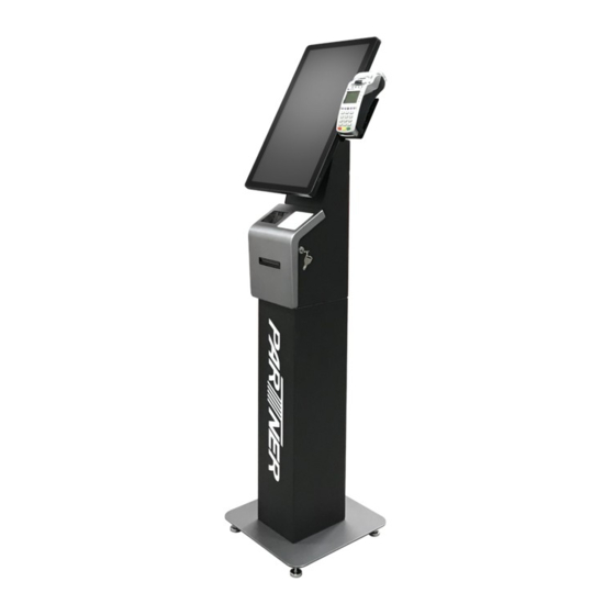
- Page 35 AD-215F Attached Payment Bracket...
- Page 36 Payment Bracket Installation, please proceed to following step for corresponding Payment Terminal: - Step 1: attached with A7. Verifone_VX-805A / Ingenico iUC285 Ingenico iPP320 / IDTECH AUGUSTA - Step 2: attached at Printed Door. Verifone_VX-805A / Ingenico iUC285 Ingenico iPP320 / IDTECH AUGUSTA - Step 3: attached at Printed Door.
- Page 37 Installation Model list ※ A7-Payment_bracket Fit Model (790AD21509000) Model(Payment) Apply Screw (Model / Bracket) Verifone_VX-805A M2x6L - 2pcs / M3x6L - 3pcs Ingenico iUC285 M4x6L - 2pcs / M3x6L - 3pcs Ingenico iPP320 M2.6x6L_Washer - 1pcs / M3x6L - 3pcs IDTECH AUGUSTA M3x6L - 2pcs / M3x6L - 3pcs...
- Page 38 Release 2 pcs M2.5x6L_Screw on A7_I/O_Cover, then Assemble I/O_Cover and A7-Payment_Bracket with 3 pcs M3x6L_screw.
- Page 39 Place Back I/O_Cover and Fasten it with 2 pcs M2.5x6L_Screw on A7. Place Payment terminal On A7-Payment_Bracket with the Screw.
- Page 40 Installation Model list ※ Payment_bracket_Option_A Fit Model (790PS11702102) Model(Payment) Apply Screw (Model / Bracket) Verifone_VX-805A M2x6L - 2pcs / Nylok_M3x4L - 4pcs Ingenico iUC285 M4x6L - 2pcs / Nylok_M3x4L - 4pcs Ingenico iPP320 M2.6x6L_Washer - 1pcs / Nylok_M3x4L - 4pcs IDTECH AUGUSTA Nylok_M3x4L - 1pcs / Nylok_M3x4L - 4pcs...
- Page 41 Assemble Payment_bracket_Option_A and Front_Door with 4 pcs M3x6L_screw.
- Page 42 Place Payment terminal On Payment_bracket_Option_ with the Screw.
- Page 43 Installation Model list ※ Payment_Bracket_Option_B Fit Model (790PS11702100) Model(Payment) Apply Screw (Model / Bracket) Verifone_VX-520 M3x9L_Washer - 2pcs / Nylok_M3x4L - 4pcs PAX_Q80 M3x9L_Washer - 2pcs / Nylok_M3x4L - 4pcs...
- Page 44 Assemble Payment_bracket_Option_ and Front_Door with 4 pcs M3x6L_screw.
- Page 45 Place Payment terminal On Payment_bracket_Option_ with the Screw.
Need help?
Do you have a question about the AD-215F and is the answer not in the manual?
Questions and answers