Advertisement
INSTRUCTION MANUAL
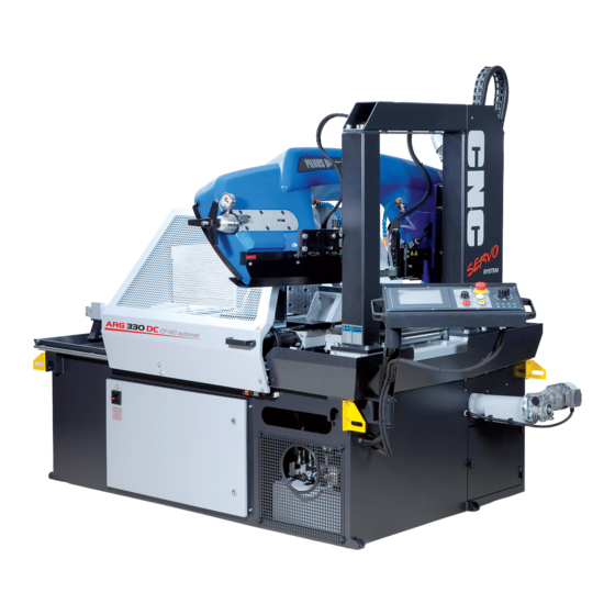
ARG 260 CF-NC automat • ARG 300 CF-NC automat
ARG 300 DCT CF-NC automat • ARG 330 CF-NC automat
ARG 330 DC CF-NC automat • ARG 520 DC CF-NC automat
2. PART
Pilous - pásové pily, spol. s r.o., Železná 9, 619 00 Brno, Czech Republic
tel.: 00 420 543 252 010
, e-mail:pilous@pilous.cz
, www.pilous.cz
Advertisement
Table of Contents

Related Manuals for Pilous ARG 260 CF-NC


Summary of Contents for Pilous ARG 260 CF-NC
- Page 1 ARG 300 DCT CF-NC automat • ARG 330 CF-NC automat ARG 330 DC CF-NC automat • ARG 520 DC CF-NC automat 2. PART Pilous - pásové pily, spol. s r.o., Železná 9, 619 00 Brno, Czech Republic tel.: 00 420 543 252 010 , e-mail:pilous@pilous.cz...
- Page 3 4.2. Control Valve - Saw Blade Feed to the Cut The control valve allows for a continuous setting of the velocity of saw blade feed towards the cut or stabilizing the saw arm in any position by mechanical closing. The optimum value of descent can be determined very easily by ear. The saw blade movement must be noiseless, free from vibrations.
- Page 4 ARG 260 NC - movable vice movable jaw fixed jaw locking handles hydraulic cylinder of the movable jaw 3 - 8 mm Release the locking handle and pull the hydraulic cylinder with moveable jaws up to the distance of 3-8 mm from the material. Lock the handle.
-
Page 5: Setting The Cutting Angle
ƒ, „, … Repeat points until the vice is completely closed and therefore adjusted. You can watch the video with instructions on www.pilous.cz. Vices ARG 300 CF-NC, ARG 300 DCT CF-NC, ARG 330 CF-NC, ARG 330 DC CF-NC Loosen all M8 LOCK NUTS and all M8 VICE PLAY SETTING SCREWS. - Page 6 Caution: Danger of injury by the sharp teeth of the saw blade. Use protective gloves. Do not reach between the wheels and the saw blade. 4.5.1. Removal of protective covers of the saw blade in ARG 260 CF-NC, ARG 300 CF-NC, ARG 300 DCT CF-NC, ARG 330 CF-NC, ARG 330 DC CF-NC Connect the machine to the mains and press the POWER SWITCH.
- Page 7 4.5.2. Removal of protective covers of the saw blade in ARG 520 DC CF-NC Connect the machine to the mains and press the POWER SWITCH. The TOTAL STOP button is unlocked. Press the SAFETY button in order to display the MAIN MENU. Start the MANUAL MODE, switch on the HYDRAULIC UNIT - START. Start the uplift of the arm and stop it above the fixed jaw of the vice, or even at the maximum lift of the arm.Close the CONTROL VALVE of the damping cylinder (see Section 4.2.), start the arm descent and by gradual releasing of the control valve, descend the arm to about 70 mm above the fixed jaw of the vice.
- Page 8 4.6. Setting the arm descent endpoint only in ARG 520 DC CF-NC Lower position end switch stops the arm descent. When cutting square or rectangular sections (I sections, U sections, etc.), it is necessary that the cutting edges of the saw blade slide under the bearing surface of the vice along the whole cutting width. Only in this way complete cut through the material can be secured.
- Page 9 4.8. Replacement, Tensioning and Adjustment of the Saw Blade A timely replacement of the saw blade is needed to achieve good cutting performance, surface finish quality and compliance with workpiece dimensions. Blunt saw blades cause high consumption of electrical power, scarf cuts and rough cutting surfaces. One of the decisive factors affecting the quality of the cut and the life of the cutting tool is the correct and sufficient saw blade tension.
- Page 10 - see section 4.6. Put back the protective covers of the saw blade, turn on the POWER SWITCH, press the SAFETY BUTTON and the hydraulic unit. Carry out the cutting. You can watch the video with instructions on www.pilous.cz.
- Page 11 COOLANT VALVE GUIDE HEAD SCREW HARDENED STEEL MOVABLE FIXED BLADE GUIDE SCREW GUIDE BAR GUIDE BAR MOVING GUIDE HEAD FIXED GUIDE HEAD FIXED HARDENED STEEL BLADE GUIDES ECCENTRIC BEARING SCREW SAW BLADE ECCENTRICALLY MOVABLE HARDENED ARRANGED BEARINGS STEEL BLADE GUIDES HARDENED STEEL HARDENED STEEL BLADE GUIDES WIDTH...
- Page 12 FLOATING HARDENED STEEL BLADE GUIDES LINER BOLTS HARDENED STEEL BLADE GUIDES PRESSURE SCREW MOVING GUIDE HEAD FIXED GUIDE HEAD CONTROL CYLINDER LINER FLOATING HARDENED STEEL BLADE GUIDES SPRINGS ECCENTRICALLY ARRANGED BEARINGS GUIDE HEAD BOLTS CONTROL SYSTEM ROLLER BOLTS OF FIXED HARDENED STEEL BLADE GUIDES CONTROL SYSTEM BEARINGS CONTROL HEAD Correct saw...
-
Page 13: Hydraulic Unit
MAIN SWITCH is turned on. The units in all machines are identical, only the ARG 520 DC CF-NC includes an extra block - marked in grey. Hydraulic unit ARG 260 CF-NC, ARG 300 CF-NC, ARG 300 DCT CF-NC, ARG 330 CF-NC, ARG 330 DC CF-NC ELECTRIC MOTOR... - Page 14 The hydraulic unit is fitted with a PRESSURE REDUCTION VALVE. It enables setting the required vice clamping force depending on the kind of the workpiece within the range: 13-35 bar in ARG 260 CF-NC, ARG 300 CF-NC, ARG 300 DCT CF-NC, ARG 330 CF-NC, ARG 330 DC CF-NC, 15-30 bar in ARG 520 DC CF-NC.
-
Page 15: Cooling System
4.11. Cooling System The pump and the coolant tank, which are mounted in the machine base, are the basic elements of the cooling system. The coolant pump conveys the coolant via hoses, valves and guide heads to the saw blade. The main cooling via the guide heads is complemented by an additional cooling system. -
Page 16: Security Check
5. Commissioning 5.1. Security Check Is everything in perfect condition with regard to safety and technical condition? Are all protective devices mounted properly? 5.2. Cutting Procedure Danger of injury! No cover on the saw blade in the cutting area! High risk of injury in the operating area of the blade! 1) Unlock the arm. -
Page 17: Machine Maintenance
AUTOMATIC MODE (see Section 4.1.2) NC MODE 0 9 : 2 0 : 0 3 0 8 / 1 0 / 2 0 1 6 SERIES LENGTH PIECES FEED SERIES LENGTH PIECES FEED SERIES KERF START PRIMARY POSITION 1) You have selected AUTOMATIC MODE 2) Turn on the HYDRAULIC UNIT START , unless you have already done so in step 3). - Page 18 - if possible, with the oil spray W44T Turbo spray approx. every 20 hours. Dense rosin oils are not suitable. Their usage can lead to blocking of the threads and breakage of the spring. By using unsuitable oils, the warranty becomes invalid. 6.4.1. Lubrication points in ARG 260 CF-NC...
- Page 19 6.4.2. Lubrication points in ARG 300 CF-NC, ARG 330 CF-NC + ARG 300 DCT CF-NC, ARG 330 DC CF-NC 6.4.3. Lubrication points in ARG 520 DC CF-NC...
- Page 20 6.5. Principles of Hydraulic Unit Maintenance FILLING CAP OIL LEVEL RETURN FILTER TRANSPORT CAP TRANSPORT CAP SCREW M10 TANK The following principles must be adhered to during the assembly of hydraulic circuit elements and piping. The basic rule in cleaning and maintenance is cleanliness and orderliness! The hydraulic circuit consists of very precise elements and it is very difficult, complicated and costly to remove any contamination and its consequences.
- Page 21 6.5.2. Commissioning The hydraulic unit is fitted with two filling holes that are covered by red transport caps during the transport. The cap that is more accessible to the operator has to be removed and replaced by a filling cap with a gauge, otherwise a risk of making the entire system inoperable arises, along with the risk of pump damage.
-
Page 22: Service Intervals
6.5.4. Hydraulic Mineral Oils HM performance class according to CETOP RP 91H European specification in viscosity classes ISO VG 32 and 46. Oils marked as HM 32 are recommended for use in environment with ambient temperatures reaching 0 °C and below 0 °C. HM 46 oil types are recommended for use in environment with ambient temperatures within the range +5 °C and +40 °C. - Page 23 7.2. Failures - Potential Causes and Remedies Possible cause Remedy Failure Saw blade feed cannot start • The power switch is off • Turn on the power switch • The TOTAL STOP button is locked. • Unlock the TOTAL STOP button •...
- Page 24 Faults reported by the system After clicking on the failure message, the machine will switch to a SYSTEM 2 screen on which you can reset the converter (if the failure is resettable). When you press the left RESET button (by the frequency converter) the screen requiring a password will appear. Enter the user password 1234 and the converter reset option will become available (press the left RESET FAILURE button again).
- Page 25 The likely cause of the failure is an open safety cover, malfunction of the BP6 limit switch or a damage to the wiring of the limit switch. After opening the cover in NC mode, the movement of the servo will be blocked. After closing the track cover and pressing the screen with the message, the machine continues working in FAILURE the automatic cycle,...
-
Page 26: Saw Blade Design
8. Saw Blades 8.1. Saw Blade Design Laser welding head High speed steel - material Heat treated alloy steel Saw Blade support strip BIMETAL The prerequisite of the correct cutting power of the machine is the use of high-quality saw blades. In order to achieve a high cutting power, it is recommended to use bimetallic saw blades. - Page 27 8.2. Selection of Tooth Size The selection of the tooth size is of crucial importance for the saw blade service life. Tooth sizes recommended for cutting full materials ARG 260, 300 NC blade 27x0,9 ARG 330 NC blade 34x1,1 ARG 520 NC blade 41x1,3 Material Number of Tooth quality...
-
Page 28: Optimum Workpiece Clamping
8.3. Optimum workpiece clamping Correct workpiece clamping can significantly influence the service life of the saw blade and the cutting accuracy. Moreover, it allows for correct selection of tooth size. To cut material in bundles, we recommend to use upper (vertical) pressure device. In order to achieve the optimum cut (service life and cutting performance), observe these ways of clamping. - Page 29 450-150 140-55 Aluminium alloy castings 50-90 50-80 450-150 140-55 do not Al 99%, thermoplastics, plastics 9. Nameplate Pilous-pásové pily, spol. s r.o. Producer MANUFACTURER Železná 9, 619 00 Brno, CZ Address MANUFACTURER`S ADDRESS Model Year MACHINE MODEL YEAR OF MANUFACTURE Serial No.
- Page 30 10. Electrical Wiring Diagram 10.1. Electrical Wiring Diagram in ARG 260 CF-NC, ARG 300 CF-NC, ARG 300 DCT CF-NC, ARG 330 CF-NC, ARG 330 DC CF-NC v 5.6 21.1.2015 1,0-1,6A 0,25-0,4A 0,6-1A 1L1 3L2 5L3 4T2 6T3 4T2 6T3 230V...
- Page 31 X1:129 COM1 COM2 COM0 Digital inputs CANopen bus PLC Schneider M241 X1:127 24VDC Outputs +24V 0V V1+ V1- 04 V2+ V2- 1 2 3 4 5 X1:149 X1:157 Chips Lighting X1:141 BP1 - blade cover IRC - arm height sensor (accessories) (Only in ARG 330) BP2 - saw blade tensioning...
- Page 32 5.6 21.1.2015 Partlist ARG 260 CF-NC, ARG 300 CF-NC, ARG 300 DCT CF-NC Diagram: Name: Type: Order No.: Limit switch FR993 with the key D1 016830 Limit switch FR615 002491 Limit switch FR6A1 002490 Limit switch FR693 with the key D1...
- Page 33 Diagram Name: Type: Order No.: MO head grip.yellow-lit M22-DL-Y 016736 mo head connection M22-A 006103 mo switch, unit 1on M22-K10 006090 MO led socket white M22-LED-W 006092 MO head sig. white M22-L-W 006095 mo head connection M22-A 006103 MO led socket white M22-LED-W 006092 MO head sig.
- Page 34 Diagram Name: Type: Order No.: The fuse holder Fuse terminal 5x20 tiltable 001779 fuse glass 500mA 004197 The fuse holder Fuse terminal 5x20 tiltable 001779 fuse glass 500mA 004197 The fuse holder Fuse terminal 5x20 tiltable 001779 Fuse glass 012712 The fuse holder Fuse terminal 5x20 tiltable 001779...
- Page 35 10.2. Electrical Wiring Diagram in ARG 520 DC CF-NC v 5.0 21.9.2015 230V 2T1 4T2 6T3 2T1 4T2 6T3 2T1 4T2 6T3 2T1 4T2 6T3 2T1 4T2 6T3 Main switch R/L1 S/L2 T/L3 24V DC U/T1 V/T2 W/T3 HO5RR-F 5Gx2,5 X1: 22 0V DC L1 brown...
- Page 36 X1:67 BP3 - Arm zeroing LMIX BP4 - Lower arm limit T.S.1 T.S.1- Pressure switch of the vice X1:73 X1:74 T.S.2- Blade tension pressure sensor +24V 0V T.S.3- Contact pressure sensor LCD panel H1 - Drive H2 - Safety relay H3 - 24 volt H4 - Blade drive failure COM0...
- Page 37 Diagram: Name: Type: Order No.: End switch Blade cover FR 993 016830 BP1.1 End switch Blade cover FR 993 016830 Blade tensioning end switch FR 615 002491 Arm resetting end switch FR 6A1 002490 Lower position limit switch FR 6A1 002490 Contactor DILEM - 10 (24V DC)
- Page 38 11. Hydraulic Unit Wiring Diagram 11.1. Hydraulic Unit Wiring Diagram in ARG 260 CF-NC, ARG 300 CF-NC, ARG 330 CF-NC, ARG 300 DCT CF-NC, ARG 330 DC CF-NC 10.2 VICE 10.1 VICE = 4,7 l/min = 40 bar UNIT TYPE NUMBER:...
- Page 39 11.2. Hydraulic Unit Wiring Diagram in ARG 520 DC CF-NC HOSE IDENTIFICATION: 1A, 1B - GUIDE FEED 2A, 2B - BLADE TENSIONING VERTICAL 10.2 3A, 3B, 4A, 4B, 5A - ARM CLAMPING 6A, 6B - VICE 7A, 7B - HVP ELECTRIC VALVES IDENTIFICATION: EV1 - CLAMP THE VICE VICE...
- Page 40 12. Accessories 12.1. Laser Guideline Light Laser guidance is a very practical tool for easy identification of the desired length of the cut material without a horizontal side stop both during perpendicular and angular cutting. The desired cutting spot is indicated by a red mark copying the saw blade. Safety warning Caution! Includes a 3R-class laser source.
- Page 41 12.2. Oil Mist Lubrication When using the standard cooling equipment, coolant leakages from the machine often occur, particularly when cutting long sections. Oil mist lubrication is a device that creates oil mist, which is subsequently applied through nozzles directly onto the saw blade that is then cooled and lubricated.
- Page 42 DOSING PUMP SETTINGS Piston vacuum pump doses the lubricant accurately and under CLICK GROOVE No. SUPPLIED VOLUME/STROKE high pressure. 41 mm 30 mm 23 mm GROOVE 1 16 mm 9 mm GROOVE 2 2 mm GROOVE 3 0 mm GROOVE 4 GROOVE 5 GROOVE 6 GROOVE 7...
- Page 43 ø 69 The HVP packet for the saw ARG 260 CF-NC includes a new movable clamping jaw and also a small clamping jaw that has to be connected onto a pre-drilled cast iron fixed clamping jaw in front of the cutting line.
- Page 44 13. Assemblies 13.1. Guide Head Assembly 13.1.1. Guide Head Assembly in ARG 260, 300 ver. 1.12.2018 Pos. Order number Name Type ARG 014056 Guide head moving 013848 Guide head moving 014055 Guide head fixed 013850 Guide head fixed 002207 Allen screw M5x50 260,300 001452 SW M5x25 screw...
- Page 45 13.1.2. Guide Head Assembly in ARG 330 ver. 1.11.2018 Pos. Order number Name Type ARG 013946 Guide head, moving 013947 Guide head, fixed 001997 Hardened steel plate 001402 Drain valve 001890 Guide head slider 014968 Exc. bearing, guide head, big 014967 Exc.
- Page 46 13.2.1. Arm assembly ARG 260 ver. 1.11.2018 Pos. Order number Name Type ARG Pos. Order number Name Type ARG 025548 Arm 260 025555 Blade cover, fixed guide head 025549 Back cover, arm 021915 Drive MRT70, i=30 025550 Upper cover 021916 Drive MRT60, i=25 260 F 025553...
- Page 47 13.2.2. Arm assembly ARG 300 ver. 1.11.2018 Pos. Order number Name Type ARG Pos. Order number Name Type ARG 023378 023377 Ring 002161 Tensioning wheel 025248 Tensioning washer 002160 Blade wheel 014108 Washer 023368 Tensioning bolt 023825 Underlying metal sheet 023369 Tensioning plate 018708...
-
Page 48: Arm Assembly
13.2.3. Arm assembly ARG 330 ver. 1.11.2018 Pos. Order number Name Type ARG Pos. Order number Name Type ARG 020841 Arm 330 020639 Spring holder, movable 012516 Tensioning wheel 020825 Spring holder screw 012515 Blade wheel 022736 Guide head cover column 001767 Tensioning bolt 025607... -
Page 49: Cooling Assembly
13.3. Cooling assembly 13.3.1.Cooling assembly in ARG 260, 300 ver. 1.10.2016 Pos. Order number Name Type ARG Coolant tank 250,300 021375 021291 Sieve 250,300 021376 Coolant tank lid 250,300 015819 Pump 1COP1-17, 20kPa/16l/min, 3x230V/3x400V, 50Hz 250,300 002403 Hose connector, tapered, 3/4”, 8 mm 250,300 001399 PVC hose DN 8x2... - Page 50 13.3.2.Cooling assembly in ARG 330 ver. 1.10.2016 Pos. Order number Name Type ARG 021375 Coolant tank 021291 Sieve 021376 Coolant tank lid 005747 Drain hose 25x320.35m 010155 Pump SAMEC AST 60/180 005458 Hose connector 1/2”x 12-13 001402 Drain valve 001398 Hose clamp 7-13 020311 Additional cooling head...
- Page 51 13.4. Cleaning Brush Assembly ver. 1.6.2017 Pos. Order number Name Type ARG 015542 Gearbox 008015 Spring pusher TL 1,5x14x60 004012 M10 Plastic nut 003548 Brush 002892 Bearing 6001-2RS 015543 Electric motor STM 0,09 kW, 1400 rpm, 230/400 V 50 Hz 003552 Brush liner 003551...
-
Page 53: Eu Declaration Of Conformity
• ČSN EN 614-1+A1:2009 Responsible for drawing up technical documentation: name, company address: Pilous-pásové pily, spol. s r.o., Železná 9, Brno 619 00, CZ, VAT: CZ60727551 This EU Declaration of Conformity is original EU Declaration of Conformity. The last two digits of the year in which the CE mark was placed on the product: 19 In Brno, on: 1.10.