
Summary of Contents for OBO Bettermann ISSMKS
- Page 1 Mediensäule für Schulen Media pole for schools DE ISSMKS Montageanleitung DE ISSMKS Mounting instructions Building Connections...
- Page 2 Mediensäule für Schulen/ Media pole for schools Montageanleitung/Mounting instructions © 2019 OBO Bettermann Holding GmbH & Co. KG Nachdruck, auch auszugsweise, sowie fotomechanische oder elektronische Wiedergabe sind untersagt! Reprinting, even of extracts, as well as photographic or electronic reproduction are prohibited!
-
Page 3: Table Of Contents
DE: Inhaltsverzeichnis DE: Inhaltsverzeichnis Über diese Anleitung . . . . . . . . . . . . . . . . . . . . .5 Zielgruppe . - Page 4 Technical data . . . . . . . . . . . . . . . . . . . . . . . . 48 4 | DE OBO Bettermann...
-
Page 5: Über Diese Anleitung
Über diese Anleitung Über diese Anleitung 1 . 1 Zielgruppe Diese Anleitung richtet sich an folgende Zielgruppen: – Elektrotechnisch geschulte Fachkräfte, die mit der Montage der Mediensäule beauftragt sind – Elektroplaner und Ingenieure, die mit der Planung von Leitungs- führungs-Systemen beauftragt sind Elektrotechnische Arbeiten dürfen nur von elektrotechnisch ge- schulten Fachkräften ausgeführt werden. -
Page 6: Bestimmungsgemäße Verwendung
– DIN EN 50085-1: 2014-05 (VDE 0604-1:2014-05) Elektroinstallationskanalsysteme für elektrische Installationen Teil 1: Allgemeine Anforderungen – DIN EN 50085-2-1: 2012-09 (VDE 0604-2-1:2012-09) Elektroinstallationskanalsysteme für elektrische Installationen Teil 2-1: Besondere Anforderungen für Elektroinstallationskanal- systeme für Wand und Decke 6 | DE OBO Bettermann... -
Page 7: Sicherheit
Sicherheit Sicherheit 2 . 1 Allgemeine Sicherheitshinweise Folgende allgemeine Sicherheitshinweise beachten: – Kontakt mit elektrischem Strom kann zu einem elektrischen Schlag führen. – Elektrotechnische Arbeiten dürfen nur von elektrotechnisch geschulten Fachkräften ausgeführt werden. 2 .2 Persönliche Schutzausrüstung – Schutzhandschuhe – Sicherheitsschuhe Mediensäule für Schulen 7 | DE... -
Page 8: Informationen Zum Produkt
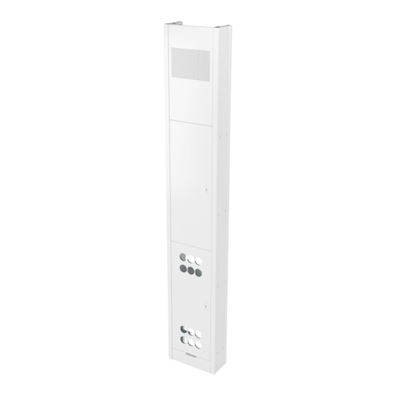
Freiraum für An dieser Postion kann eine Wanduhr optional montiert Wanduhr werden. Der Durchmesser der Wanduhr darf 300 mm nicht überschreiten. Tür Kleinverteiler Die abschließbare Tür dient als Zugriffsschutz für die dahinter liegenden Kleinverteiler. 8 | DE OBO Bettermann... - Page 9 Informationen zum Produkt Nr . Produktname Abbildung Funktion Seitenverkleidung Die Seitenverkleidungen verdecken die äußeren Seiten der Mediensäule. Tür Gerätefeld Die Tür Gerätefeld dient zur Aufnahme verschiedener Steckdosen und Multimedia/Datentechnikanschlüsse. Die Tür schützt das innenliegende Gerätefeld vor Zugriff. Leitungsauslass Durch den Leitungsauslass werden Kabel in die Medien- säule eingeführt, die im Gerätefeld eingesteckt werden.
-
Page 10: Mediensäule Montieren
Umkippen und damit zu schweren körperlichen Verlet- zungen (z.B. Quetschungen) führen. Mediensäule mit zwei Monteuren vorsichtig montieren. 4 . 1 Mediensäule an der Wand montieren Hinweis! Bei den Handlungsschritten 1 bis 3 ist es hilfreich, die Mediensäule auf den Boden zu legen. 1. Mediensäule vom Verpackungsmaterial befreien. 10 | DE OBO Bettermann... - Page 11 Mediensäule montieren Abb . 2: Seitenblende demontieren 2. Befestigungsschrauben an der Seitenverkleidung lösen und beide Seitenverkleidungen abnehmen. Abb . 3: Türen demontieren 3. Scharnierbolzen an den Scharnieren hoch drücken (1.) und anschließend um 90 °drehen (2.). Türen abnehmen. Mediensäule für Schulen 11 | DE...
- Page 12 7. Mediensäule in der vorher definierten Postion an der Wand positionieren und mit geeignetem Befestigungsmaterial befesti- gen. 8. Tür Kleinverteiler und Tür Gerätefeld wieder (in umge- kehrter Reihenfolge) montieren (siehe „4.1 Mediensäule an der Wand montieren“ auf Seite 11). Hinweis! Die Montage der Seitenverkleidung erfolgt zu einem späteren Zeitpunkt. 12 | DE OBO Bettermann...
-
Page 13: Galgen Montieren
Mediensäule montieren 4 .2 Galgen montieren Abb . 5: Galgen montieren 1. Befestigungsschrauben am Galgen lösen, Galgen gegen die Decke schieben (1.) und mit Befestigungsschrauben fixie- ren (2.). 2. Seitenverkleidung montieren. Mediensäule für Schulen 13 | DE... -
Page 14: Mediensäule Anpassen
(1.) und mit den 4 Befestigungsschrauben fixieren (2.). Mediensäule anpassen 5 . 1 Türanschlag wechseln Hinweis! Die Öffnungsrichtung der Tür kann durch das Wechseln der Türen von einer Linkstür auf eine Rechtstür getauscht werden. 1. Tür Gerätefeld und Tür Kleinverteiler demontieren (siehe „4.1 Mediensäule an der Wand montieren“ auf Seite 11). 14 | DE OBO Bettermann... - Page 15 Mediensäule anpassen Abb . 7: Scharnierbleche, Gegenlager Türauflagen und Türanschläge demontie- 2. Türanschläge ,Türauflagen (1.) und Gegenlager (2.) abschrauben und an der gegenüberliegenden Seite montieren (siehe „4.1 Mediensäule an der Wand montieren“ auf Seite 11). Mediensäule für Schulen 15 | DE...
- Page 16 Mediensäule anpassen Abb . 8: Riegelschloss ausbauen 3. Obere und untere Riegelschloss Schraube lösen und Blende, Distanzhülsen sowie Riegelschloss zerlegen. Seitliche Ver- schraubung am Riegelschloss lösen und Profilhalbzylinder entnehmen. 16 | DE OBO Bettermann...
- Page 17 Mediensäule anpassen Abb . 9: Riegelschloss einbauen 4. Riegelschloss und Schließzylinder spiegelverkehrt wieder mon- tieren. Abb . 10: Türen montieren Mediensäule für Schulen 17 | DE...
-
Page 18: Verdrahtungskanäle Demontieren
2. Befestigungsschrauben der Verdrahtungskanäle lösen und Verdrahtungskanäle von oben aus der Mediensäule rauszie- hen. 5 .3 Kleinverteiler demontieren 1. Seitenverkleidung , Tür Kleinverteiler und Seitenblenden demontieren (siehe „4.1 Mediensäule an der Wand montie- ren“ auf Seite 11). 18 | DE OBO Bettermann... - Page 19 Mediensäule anpassen Abb . 12: Blende der Kleinverteiler demontieren 2. Befestigung der Blenden des Kleinverteilers mit einem Schraubenzieher lösen und Blenden abziehen. Abb . 13: Kleinverteiler demontieren 3. Befestigungsblech Kleinverteiler abschrauben (1.) und Klein- Mediensäule für Schulen 19 | DE...
-
Page 20: Mediensäule In Die Schutzmaßnhame Einbeziehen
Abb . 14: Kleinverteiler rausnehmen Mediensäule in die Schutzmaßnhame einbeziehen Hinweis! Der Einbezug in die Schutzmaßnahme erfolgt über einen Erdungs- anschluss im Nutenprofil des Grundgerüstes (Abb. 15). Die Er- dungsleitungen der Türen sind nach vollendeter Montage mit dem Grundgerüst zu verbinden (Abb. 16). Alle weiteren Bauteile sind leitend miteinander verbunden. 6 . 1 Säulenkorpus in die Schutzmaßnahme einbeziehen 1. Seitenverkleidung demontieren (siehe „4.1 Mediensäule an der Wand montieren“ auf Seite 11). 20 | DE OBO Bettermann... - Page 21 Mediensäule in die Schutzmaßnhame einbeziehen Abb . 15: Mediensäule erden 2. Mediensäule über den Erdungspunkt mit einem Kabelschuh erden. 3. Seitenverkleidung montieren. Mediensäule für Schulen 21 | DE...
-
Page 22: Türen În Die Schutzmaßnahme Einbeziehen
Verbindung herstellen. Zubehör montieren 7 . 1 Lautsprecher montieren Hinweis! Die Lautsprecher können über die Hutschienen hinter dem Akus- tikfeld montiert werden. 1. Befestigungsschrauben an der Seitenverkleidung lösen und beide Seitenverkleidungen demontieren (siehe „4.1 Medien- säule an der Wand montieren“ auf Seite 11). 22 | DE OBO Bettermann... - Page 23 Zubehör montieren Lautsprecher montieren Abb . 17: 2. Befestigungsschrauben des Akustikfeldes lösen und Lautspre- cher auf der C-Schiene entsprechend der Herstellervorgaben montieren. Mediensäule für Schulen 23 | DE...
-
Page 24: Steckdosen Montieren
Abb . 18: Steckdosen montieren 1. Hohlwanddosen in den dafür vorgesehenen Bohrungen der Gerätefelder (innen und außen) installieren. 2. Schalt- und Steckgeräte in den Hohlwanddosen installieren. 3. Anschlussleitungen rückseitig bündeln und über die Verdrah- tungskanäle verteilen. 24 | DE OBO Bettermann... -
Page 25: Wanduhr Montieren
Mediensäule demontieren 7 .3 Wanduhr montieren Abb . 19: Wanduhr montieren 1. Wanduhr auf der oberen Blende (Freiraum für Wanduhr nach Herstellerangaben montieren. Mediensäule demontieren Hinweis! Die Mediensäule kann an einer neuen Position erneut montiert werden. 1. Mediensäule analog der Montage demontieren. Mediensäule entsorgen – Verpackung wie Hausmüll –... -
Page 26: Technische Daten
Technische Daten Technische Daten Mediensäule für Schulen ISSMKS Art.-Nr. Mediensäule 6286721 Art.-Nr. Blenden Höhenerweiterung 190 mm: 6286790 Höhenerweiterung 355 mm: 6286796 Höhenerweiterung 520 mm: 6286798 Abmessungen L x B x H 200 x 460 x 2850 mm Gewicht 87,5 kg... - Page 27 EN: Table of contents EN: Table of contents About these instructions . . . . . . . . . . . . . . . . . . 28 Target group .
-
Page 28: About These Instructions
Type of risk! ATTENTION Shows a hazardous situation. If the safety instruction is not ob- served, then damage to the product or the surroundings may occur. Note! Indicates important information or assistance. 28 | EN OBO Bettermann... -
Page 29: Correct Use
About these instructions 1 .4 Correct use The media and communication pole is used to accept electrical installation components and for vertical, multi-storey cable routing. The media and communication pole consists of: – An acoustic panel with punch-outs for noise escape –... -
Page 30: Safety
– Contact with electrical current can lead to an electric shock. – Electrical work may only be carried out by specialist personnel with electrical training. 2 .2 Personal protective equipment – Protective gloves – Safety shoes 30 | EN OBO Bettermann... -
Page 31: Information On The Product
Information on the product Information on the product 3 . 1 System components Fig . 1: Overview of system components No . Product name Figure Function Boom The boom is used to adjust the height of the media pole. Acoustic panel A loudspeaker can optionally be mounted behind the acoustic panel. - Page 32 Small distributor Small distributor panel with 2 low-voltage distributors (2x 36 PUs). Wiring The cables of the devices can be wired and connected via trunking the wiring trunking. 32 | EN OBO Bettermann...
-
Page 33: Mounting The Media Pole
Mounting the media pole No . Product name Figure Function Connection plate The connection plates connect the front and rear frame profiles. Separable cable Cables in the ceiling area can be inserted into the media gland pole with strain relief via the cable glands. Extension panel The extension panel hides the distance between the media pole and the ceiling. - Page 34 4. Position the media pole on the wall. Note! Depending on requirements, the height of the fastening straps can be adjusted. In so doing, distribute the fastening straps evenly over the entire length of the media pole. 5. Position the fastening straps and mark the appropriate pos- ition. 6. Take the media pole away from the wall and pre-drill the marked drill holes. 34 | EN OBO Bettermann...
- Page 35 Mounting the media pole Fig . 4: Screwing the media pole tight 7. Position the media pole in the previously defined position on the wall and fasten using suitable fastening materials. 8. Remount (in reverse order) the small distributor door device panel door (see “4.1 Mounting the media pole on the wall”...
-
Page 36: Mounting The Boom
Mounting the boom 1. Slacken the fastening screws on the boom , push the boom against the ceiling (1.) and fix with fastening screws (2.). 2. Mount the side panelling Fig . 6: Mounting the ceiling rosette 36 | EN OBO Bettermann... -
Page 37: Adjusting The Media Pole
Adjusting the media pole 3. Position the ceiling rosette (1.) and fix with the 4 fastening screws (2.). Adjusting the media pole 5 . 1 Exchanging the door stop Note! The opening direction of the door can be switched by changing the doors from a left door to a right door. 1. Dismantle the device panel door and small distributor door (see “4.1 Mounting the media pole on the wall”... - Page 38 Fig . 8: Removing the bolt lock 3. Slacken the top and bottom bolt lock screw and dismantle the panel, spacer sleeves and bolt lock. Slacken the side gland on the bolt lock and remove the profile half cylinder. 38 | EN OBO Bettermann...
- Page 39 Adjusting the media pole Fig . 9: Installing the bolt lock 4. Remount the bolt lock and closing cylinder back-to-front. Fig . 10: Mounting the doors Media pole for schools 39 | EN...
-
Page 40: Dismantling Wiring Trunking
5 .3 Dismantling the small distributor 1. Dismantle the side panelling , small distributor door side screens (see “4.1 Mounting the media pole on the wall” on page 11). 40 | EN OBO Bettermann... - Page 41 Adjusting the media pole Fig . 12: Dismantling the screen of the small distributor 2. Release the fastening of the screens of the small distributor with a screwdriver and remove the screens. Fig . 13: Dismantling the small distributor 3. Unscrew the fastening panel of the small distributor (1.) and Media pole for schools 41 | EN...
-
Page 42: Including The Media Pole In The Protective Measure
Note! The inclusion in the protective measure takes place via an earthing connection in the groove profile of the base frame (Fig. 15). After completed mounting, connect the earthing cables of the doors with the base frame (Fig. 16). All other components have a conductive connection. 6 . 1 Including the pole body in the protective measure 1. Dismantle the side panelling (see “4.1 Mounting the media pole on the wall” on page 11). 42 | EN OBO Bettermann... - Page 43 Including the media pole in the protective measure Fig . 15: Earthing the media pole 2. Earth the media pole via the earthing point with a cable lug. 3. Mount the side panelling Media pole for schools 43 | EN...
-
Page 44: Including The Doors In The Protective Measure
7 . 1 Mounting loudspeakers Note! The loudspeakers can be mounted behind the acoustic panel using the hat rails. 1. Slacken the fastening screws on the side panelling and dis- mantle both side panels (see “4.1 Mounting the media pole on the wall” on page 11). 44 | EN OBO Bettermann... - Page 45 Mounting accessories Mounting loudspeakers Fig . 17: 2. Slacken the fastening screws of the acoustic panel and mount the loudspeaker on the C rail according to the manufacturer’s specifications. Media pole for schools 45 | EN...
-
Page 46: Mounting Sockets
1. Install the cavity wall sockets in the provided drill holes of the device panels (interior and exterior). 2. Install switching and connection devices in the cavity wall sockets. 3. Bundle the connection cables at the rear and distribute them across the wiring trunking 46 | EN OBO Bettermann... -
Page 47: Mounting A Wall Clock
Dismantling the media pole 7 .3 Mounting a wall clock Fig . 19: Mounting a wall clock 1. Mount the wall clock on the top panel’s free space for a wall clock according to the manufacturer’s specifications. Dismantling the media pole Note! The media pole can be mounted in a new position. -
Page 48: Technical Data
Technical data Technical data Media pole for schools Type ISSMKS Item no. media pole 6286721 Item no. panels Height expansion 190 mm: 6286790 Height expansion 355 mm: 6286796 Height expansion 520 mm: 6286798 Dimensions L x W x H 200 x 460 x 2,850 mm Weight 87.5 kg... - Page 49 Technical data Media pole for schools 49 | EN...
- Page 50 Technical data 50 | EN OBO Bettermann...
- Page 51 Technical data Media pole for schools 51 | EN...
- Page 52 OBO Bettermann Holding GmbH & Co. KG P.O. Box 1120 58694 Menden GERMANY Customer Service Tel.: +49 (0)23 71 78 99 - 20 00 Fax: +49 (0)23 71 78 99 - 25 00 export@obo.de www.obo-bettermann.com Building Connections...
Need help?
Do you have a question about the ISSMKS and is the answer not in the manual?
Questions and answers