Table of Contents
Advertisement
Quick Links
8. DIMENSIONS AND FLOW RATES
Flow Rates (in GPH)
Model
Min.
Normal Flow Range
Q1
Q2
Q3
WMPD-050
4.13
6.6
660
WMPD-075
6.6
10.6
1056
Ø W
T
9. ACCURACY CURVE
+5%
+2%
WMPD050
WMPD075
0%
-2%
-5%
Q1
Q2
Flow Rate
© Assured Automation 2015
Dimensions (in inches)
Max.
Q4
L
L1
T
W
825
4.53
8.23
1/2 NPT
3.78
1320
6.50 10.16
3/4 NPT
4.17
L1
L
Q3
Q4
Weight
(in lbs.)
WM-PD Series
1.5
1.5
Use & Care Manual
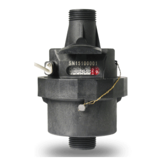
1. GENERAL INFORMATION
WM-PD plastic water meters use a volumet-
ric piston displacement method to advance
a register that is emersed in ethylene glycol.
These meters are tamper proof due to a
tamper evident that prevents the body from
being opened or taken apart. DO NOT RE-
MOVE THIS WIRE! If the wire is removed, or
altered in any way, the warranty is void.
2. SPECIFICATIONS
T
Max. Temperature: up to 122°F (50°C)
Orientation: Any
Pulse Output Max. Voltage: 24vAC/DC
Pulse Output Max. Current: 20mA
Maximum Total: 999,999.99 gallons
Accuracy: ±2% (Q2 to Q4) ±5% (Q1 to Q2)
(see curves on back cover)
3. METER INSTALLATION
General Considerations
1. Completely flush the water line upstream of
the meter to remove any possible dirt and debris.
2. The meter can be installed in any orientation
with the direction of flow matching the
arrow that is molded into the body. The
register face can be positioned in any
orientation 360° around. It should be
positioned with easy access to reading it
in mind.
3. The meter must remain full of water at all
times for accurate measurement.
WM-PD-2015
1-800-899-0553
assuredautomation.com
4. The meter should be installed lower than
the outlet to produce a slight back-flow
pressure. This will help ensure accuracy.
5. A length of 3 times the inner diameter of
the pipe line should be present upstream
of the meter. (see drawing on left)
min. 3x Ø
Flow Direction Arrow
(WMPD-075 shown here)
Location of Flow Direction Arrows
on the WMPD-050 (both sides)
Advertisement
Table of Contents

Subscribe to Our Youtube Channel
Related Manuals for Assured Automation WM-PD Series

Summary of Contents for Assured Automation WM-PD Series
- Page 1 WMPD-050 (both sides) orientation 360° around. It should be Flow Rate positioned with easy access to reading it in mind. 3. The meter must remain full of water at all times for accurate measurement. © Assured Automation 2015 WM-PD-2015...
- Page 2 There is no reset function for these meters. In no event shall Assured Automation be liable The meters are sealed shut with a tamper for incidental or consequencial damages of evident wire. The meters will operate main- any kind, including but not limited to loss of tenance free for their entire service life.
Need help?
Do you have a question about the WM-PD Series and is the answer not in the manual?
Questions and answers