Table of Contents
Advertisement
Advertisement
Table of Contents

Related Manuals for qutools quTAG MC


Summary of Contents for qutools quTAG MC
- Page 1 MC Time-to-Digital Converter Manual V1.0...
-
Page 2: Table Of Contents
Contents Introduction ........................4 quTAG MC – state of the art time-to-digital converter ..........4 Technical overview ....................4 Jitter Measurement ....................5 Safety and Maintenance ....................6 Legend ........................6 General Instructions ....................6 Environmental Conditions ..................7 Electrical Installation ....................7 Preventive Maintenance ................... - Page 3 Unexpected Delays ....................34 Low Resolution ......................35 Revision History ......................36 www.qutools.com quTAG MC Manual...
-
Page 4: Introduction
MC – state of the art time-to-digital converter The quTAG MC – Multi Channel – is a time-to-digital converter that measures electric signals and marks them with time tags. This stream of time tags can be used in various and versatile applications –... -
Page 5: Jitter Measurement
σ / √2 from this two-channel measurement, assuming equal Gaussian contributions from both signals. The FWHM can be obtained by the standard deviation with the relation FWHM = 2 √2 ln 2 σ ≈ 2.35 σ. www.qutools.com quTAG MC Manual... -
Page 6: Safety And Maintenance
In particular, excessive moisture may impair safety. For laboratory use only. This unit is intended for operation from a normal, single phase supply, in the temperature range 5° to 40°C, 20% to 80% RH. quTAG MC Manual www.qutools.com... -
Page 7: Environmental Conditions
Maintenance is limited to safety testing and cleaning as described in the following sections. www.qutools.com quTAG MC Manual... -
Page 8: Safety Testing
The quTAG parts are sensitive to any kind of liquid. Do not use any type of abrasive pad, scouring powder, or solvent, e.g. alcohol or benzene. Please note that all parts of quTAG are cleaned in our production facility. quTAG MC Manual www.qutools.com... -
Page 9: Technical Specifications
Rising, falling Min. input pulse width 1 ns Termination 50 Ohm Output Channels Number of channels Connector D-Sub, Pins 3 & 1 Signal levels LVTTL Delay range -100… 100 ns Delay resolution 10 ps Impedance 50 Ohm www.qutools.com quTAG MC Manual... - Page 10 D-Sub, Pins 7, 6, 20, 19 Sync Output Signal type Square wave Frequency 10 MHz Signal level LVTTL Output impedance 50 Ohms Connector Operation Interface USB3.0 Operating system Windows, Linux Power consumption < 50W at 100 to 230 VAC, 50-60 Hz quTAG MC Manual www.qutools.com...
-
Page 11: Variants And Options
4 Variants and Options The quTAG MC can be upgraded with the following features. The optional features that can also be installed individually. The basic variant does not include any of the options listed below. For the procedure of installation refer to section 6.4 . -
Page 12: Hardware Description
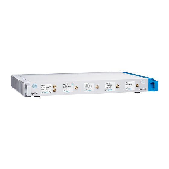
5 Hardware Description 5.1 Front side The quTAG MC comes in different variants with 8, 16 or 32 stop input channels. Figure 1: Front side of the quTAG MC - 8 stop input channels Figure 2: Front side of the quTAG MC - 16, 32 stop input channels... -
Page 13: Displays On The Front Panel
Filter (see section 7.7 for details) active on that channel 5.3 Rear side Figure 3: Rear side of the quTAG MC 32 channels Make sure the cooling fans are not obstructed. Otherwise, the quTAG may be damaged due to overheating. -
Page 14: Marker Inputs
Marker inputs 1...4 reside on pins 7, 6, 20, 19. Use the additionally shipped breakout cable. If configured by software, Marker events are saved within the data stream as timestamps. Channel numbers 100-103 are the Markers 1-4 with rising edge and 105-108 with falling edge. quTAG MC Manual www.qutools.com... -
Page 15: Output Channels
The GPIO Connector is used for those outputs: Figure 5: D-Sub connector at the back panel The output channels 1 and 2 reside on pins 3 and 1. Use the additionally shipped breakout cable. www.qutools.com quTAG MC Manual... -
Page 16: Synchronization
The clock input hasn't to be connected in most cases. It is used only to synchronize the device with an external clock source. • "Payload" signals are connected to the start and the stop input connectors, see input channel specifications. quTAG MC Manual www.qutools.com... -
Page 17: Software Installation And Configuration
"runflasher" instead of "daisy" and "nhflash" will do the job. To call the programs (or userlib applications) directly, the library path has to be published. This may be achieved a) temporarily: add the extra search path to your shell: export LD_LIBRARY_PATH=$LD_LIBRARY_PATH:/home/me/daisy www.qutools.com quTAG MC Manual... -
Page 18: Firmware Update
1. Turn on the device. If any quTAG software is still running, close it. quTAG MC Manual www.qutools.com... -
Page 19: Hardware Id
(or open the program menu using ctrl+F9 and select file/ load panel). Enter an individual ID and press "Save". Close the program window and restart the device. Figure 7: Programming the Hardware ID www.qutools.com quTAG MC Manual... -
Page 20: Option Upgrade
"feature.ngc" in the installation folder and drag it into the program window (or open the program menu using ctrl+F9 and select file/load panel). Enter the key obtained from the vendor and press Enter. Close the program window and restart the device. Figure 8: Option upgrade quTAG MC Manual www.qutools.com... -
Page 21: Daisy Software
65.5 s. The count rates can be saved to a text file by pressing on the button next to "Save Counts". The button with two red dots will save the count rates continuously after every exposure time. www.qutools.com quTAG MC Manual... - Page 22 If configured, Marker events and time ticks are saved within the data stream as timestamps. Channel numbers 100-103 are the Markers 1-4 with rising edge, 105-108 with falling edge and 104 is the millisecond time tick. quTAG MC Manual www.qutools.com...
-
Page 23: Coincidences
Two (or more) detection events will be counted as a coincident event if the difference of their time stamps is less or equal than the specified time window. The trend of a selected count rates can be displayed in the line graphs. Figure 10: Coincidence counting tab of Daisy www.qutools.com quTAG MC Manual... -
Page 24: Histograms
If "Diffs" is not selected the absolute value of individual timestamps are added to the histogram. Use this setting if the time between events on the start input and a stop input is of interest. quTAG MC Manual www.qutools.com... -
Page 25: Correlation Measurement: Hbt
Select "active" to start collecting the correlation data. The "Results" shows several parameters of the current measurement including the event rates, measurement time and the g (0) value. www.qutools.com quTAG MC Manual... - Page 26 Additional fit models which take detector offsets and jitter into account are available. If they are used, the appropriate values for the detectors have to be entered in the "Detector Parameters" field. The "Data Generation" dialog allows to demonstrate the functions with data generated by one of the model functions. quTAG MC Manual www.qutools.com...
-
Page 27: Lifetime Measurement
In the "Fitting" field a model function for the fit can be chosen. The result of the fit is displayed in the bottom field. The fit is only valid, if the number next to "Fit Success" is positive. If no fit can be found, please adjust the starting values using the "Edit Start Values" button. www.qutools.com quTAG MC Manual... -
Page 28: Detector Parameter Settings
"Detector Parameters". After a restart of the device, all channels are by default configured to detect the rising edge of input signals at a trigger level of 1 V, which is suitable for LVTTL signals. Figure 14: Input parameter settings in Daisy quTAG MC Manual www.qutools.com... - Page 29 The process doesn't require user support and is run each time Daisy is started. It can be retriggered by clicking "Start" in the calibration part. www.qutools.com quTAG MC Manual...
-
Page 30: Filters
This filter is useful e.g., for a laser trigger signal when there is not a lot of detection signals. Trigger events not followed by a detection event are useless and will be suppressed. None No filtering. quTAG MC Manual www.qutools.com... - Page 31 Figure 15: Filters can be applied in the Daisy software at the "Detector Parameters" tab. www.qutools.com quTAG MC Manual...
-
Page 32: Other Software Components
"Detector Parameters" tab in daisy introduced in section 7.6 . Whether a text or a binary output file is created and their filenames can be chosen next to "Text Output" and "Binary Output". Recording data is controlled using the "Start" and "Stop" buttons. quTAG MC Manual www.qutools.com... -
Page 33: Command Line Interface
To use it, open a command prompt, go to the software directory and call tdccli(.exe). Use the parameter -h for additional information. The CLI program also serves as an example DLL application. The source code is available in userlib\cli. www.qutools.com quTAG MC Manual... -
Page 34: Faq / Trouble Shooting
On delivery, the delays are not calibrated. Solution To remove the runtime difference between two channels, connect them with input signals of known pulse distance and adjust the signal runtime until the quTAG reproduces the known value. quTAG MC Manual www.qutools.com... - Page 35 9.4 Low Resolution Problem The quTAG MC has very low time resolution. Cause After starting the quTAG, the internal electronics are not in a thermal equilibrium. When the device temperature changes in the first minutes, the timing jitter degrades due to the different conditions at the startup calibration.
- Page 36 10 Revision History Revision Date Changes 1.0.0 2021-01-01 initial release quTAG MC Manual www.qutools.com...
Need help?
Do you have a question about the quTAG MC and is the answer not in the manual?
Questions and answers