Table of Contents
Advertisement
Quick Links
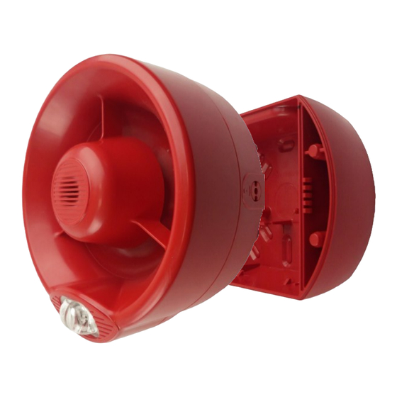
HYFIRE TYPE B WALL SOUNDER + VISUAL ALARM DEVICE
OVERVIEW
This device is an assembly of an HFW-SIM-01-AS Hyfire system interface module and a HFC-WSR-03 conventional sounder / HFC-SBR-23-
03 conventional sounder + visual alarm device. Sounder's output is activated following an alarm condition of the Hyfire system.
INSTALLATION - IMPORTANT NOTES
- The device must be installed following your national and/or international codes of practice and standards: check them before performing the
installation of this device.
- Test this device after installation.
1) Detach the front operating section from the sounder back box (→ SOUNDER OPENING PROCEDURE).
2) Extract the HFW-SIM-01-AS from the sounder's back box (→ MODULE'S EXTRACTION).
3) Set the HFW-SIM-01-AS's link switch to ON.
4) Extract the HFW-SIM-01-AS's battery covers.
5) Insert both batteries into their HFW-SIM-01-AS holders, oriented as per polarity marks.
6) Link the HFW-SIM-01-AS device to the Hyfire system (→ LINKING).
7) Reinstall the battery covers.
8) Check the wireless link quality of the HFW-SIM-01-AS positioned in the final installation location (→ WIRELESS LINK QUALITY
CHECK).
9) Install the sealing pad if the sounder is to be installed outdoors and/or in damp environments (not EN 54-3 approved)
(→ OUTDOORS AND DAMP ENVIRONMENTS INSTALLATION).
10) Fix the sounder back box to the wall on the final installation location (→ WALL INSTALLATION).
11) Reinstall the HFW-SIM-01-AS into the sounder's back box (→ MODULE'S INSTALLATION).
12) Set sounder's tone and volume (→ OUTPUT TONE SETTING , →OUTPUT VOLUME SETTING).
13) Reinstall the front operating section onto the sounder back box (→ SOUNDER CLOSING PROCEDURE).
14) Test the HFW-SIM-01-AS + HFC-WSR-03 / HFC-SBR-23-03 to check if it works properly (→ TESTING).
HFW-SIM-01-AS + HFC-WSR-03
HFW-SIM-01-AS + HFC-SBR-23-03
HYFIRE TYPE B WALL SOUNDER
INSTALLATION
Advertisement
Table of Contents

Subscribe to Our Youtube Channel
Related Manuals for Incite Fire HFW-SIM-01-AS

Summary of Contents for Incite Fire HFW-SIM-01-AS
- Page 1 HYFIRE TYPE B WALL SOUNDER + VISUAL ALARM DEVICE OVERVIEW This device is an assembly of an HFW-SIM-01-AS Hyfire system interface module and a HFC-WSR-03 conventional sounder / HFC-SBR-23- 03 conventional sounder + visual alarm device. Sounder’s output is activated following an alarm condition of the Hyfire system.
- Page 2 SOUNDER OPENING PROCEDURE When assembling or removing the front operating In order to detach the upper sounder body from the base: section of the sounder to/from the back box be careful to ensure the interconnection block is not 1) Insert the pins of the compatible key into the holes of one of the two side twisted which may cause damage.
- Page 3 1) Move the link switch’s cursor from ON to the opposite side (BLANK side); HFW-SIM-01-AS indicates “Linking to the system”. 2) If linking outcome is ok: HFW-SIM-01-AS stops indicating “Linking to system”. 3) If linking outcome is not ok: perform the LINKING RECOVERY procedure.
-
Page 4: Wall Installation
OUTDOORS AND DAMP ENVIRONMENTS INSTALLATION When installing the sounder outdoors or in a damp environment, carefully apply the self-adhesive sealing pad to the back of the sounder base (picture 5). WALL INSTALLATION Fix the sounder base to the wall; the prepared location options for the fixing screws are highlighted in picture 6. Picture 5 Picture 6 MODULE’S INSTALLATION... - Page 5 OUTPUT TONE SETTING Use the DIP switch on the back of the sounder body to select the tone required; for this function the first five switches are used, highlighted in picture 8. Picture 8 The switches positioned upwards acquire value “1”; on the other hand, if positioned downwards acquire value “0”. 1) From the →TONE SET table (table 4) select the output alarm tone triggered when the sounder is activated.
- Page 6 TONE SET DIP switch Tone Tone designation Tone description configuration: number 1,2,3,4 e 5 Warble Tone 800Hz for 500ms, then 1000Hz for 500ms 11101 Continuous tone 970Hz continuous tone 01011 Slow Whoop (Dutch) 500-1200Hz for 3500ms, then off for 500ms 10101 German DIN tone 1200-500Hz swept every 1000ms (1Hz)
- Page 7 SOUNDER CLOSING PROCEDURE In order to assemble the sounder body to the base: 1) Assemble the sounder body to the base using gentle pressure (picture 10). 2) Insert the pins of the compatible key into the holes of one of the two side locking mechanisms.
-
Page 8: Battery Replacement
6) Reinstall the battery covers. 7) Reinstall the HFW-SIM-01-AS into the sounder’s back box. 8) Reinstall the front operating section onto the sounder back box. 9) Test the HFW-SIM-01-AS + HFC-WSR-03 / HFW-SIM-01-AS + HFC-SBR-23-03 to check if it works properly. - Page 9 Picture 13...
- Page 10 60 days from first appear- ance of the low battery warning Parent expander’s check-up period 7 seconds (default setting) TECHNICAL SPECIFICATIONS (HFW-SIM-01-AS + HFC-WSR-03) Max current draw (at 3 V) 50 mA Acoustic emission frequency range. 440 - 2900 Hz Valid for all tones Maximum acoustic intensity, volume set to HIGH.
-
Page 11: Warnings And Limitations
Smoke detectors may respond differently to various kinds of smoke particles, thus application advice should be sought for special risks. Detectors cannot respond HFW-SIM-01-AS + HFC-WSR-03 correctly if barriers exist between them and the fire location and may be affected HFW-SIM-01-AS + HFC-SBR-23-03 by special environmental conditions.
Need help?
Do you have a question about the HFW-SIM-01-AS and is the answer not in the manual?
Questions and answers