Table of Contents
Advertisement
Quick Links
Advertisement
Table of Contents

Related Manuals for Northern Meditec Crius V6


Summary of Contents for Northern Meditec Crius V6
- Page 1 Crius V6 Ventilator Operator’s Manual 1 / 182...
- Page 2 © 2015-2017 ShenZhen Northern Meditec Co., Ltd.All rights Reserved. For this Operator’s Manual, the issue date is Aug, 2017. 2 / 182...
- Page 3 Shenzhen belongs Northern Meditec Co., Ltd. (hereinafter referred to as "Northern"). The User’s Manual contains exclusive data under the protection of law of copyright. All rights reserved. Any individual or organization must not reproduce, amend or translate the any part of the User’s Manual without prior written approval from our company.
- Page 4 Responsibility on the Manufacturer Party Contents of this manual are subject to change without prior notice. All information contained in this manual is believed to be correct. Northern shall not be liable for errors contained herein or for incidental or consequential damages in connection with the furnishing, performance, or use of this manual.
- Page 5 Warranty THIS WARRANTY IS EXCLUSIVE AND IS IN LIEU OF ALL OTHER WARRANTIES, EXPRESSED OR IMPLIED, INCLUDING WARRANTIES OF MERCHANTABILITY OR FITNESS FOR ANY PARTICULAR PURPOSE. In accordance with the conditions of storage and use, from the date of the factory 2 years, the ventilator can not work properly, the company free of charge for the user repair, replacement parts or products.
- Page 6 Customer Service Department Manufacturer: Shenzhen Northern Meditec Co., Ltd. Address: Floor 4, Block C, Gold Power Industry Park, julongshan, Grand industrial Zone, Pingshan New District, Shenzhen(518102), P.R.China Website: www.northernmeditec.com E-mail Address: info@northernmeditrc.com Tel: +86 755 29970566 Fax: +86 755 23010276 EC-Representative: Obelis S.A.
- Page 7 Preface Manual Purpose This manual contains the instructions necessary to operate the product safely and in accordance with its function and intended use. Observance of this manual is a prerequisite for proper product performance and correct operation and ensures patient and operator safety. This manual is based on the maximum configuration and therefore some contents may not apply to your product.
-
Page 8: Table Of Contents
Table of Contents Chapter 1 Safety ........................16 1.1 Safety Information ........................ 16 1.1.1 Dangers ........................17 1.1.2 Warnings ......................... 17 1.1.3 Cautions ........................19 1.1.4 Notes 21 1.2 Equipment Symbols ......................21 1.3 Symbols and Abbreviations ....................23 1.3.1 Unit 23 1.3.2 Symbols ........................ - Page 9 4.4 User Screen .......................... 47 4.5 Measured Values Screen ...................... 49 4.6 History Data ......................... 50 4.6.1 Tabular Trend ......................50 4.6.2 Graphic Trend ......................51 4.6.3 Event Log ........................ 53 4.7 Big Font Screen ........................54 4.8 Big Loop Screen ........................54 4.9 Freeze 55 4.8.1 Enter freeze status ....................
- Page 10 5.17.4 Set Psupp ...................... 61 5.17.5 Set Pinsp ....................... 61 5.17.6 Set Tinsp ....................... 62 5.17.7 Set Rate ......................62 5.17.8 Set Texp ......................62 5.17.9 Set Trigger ....................63 5.17.10 Set Tslope ..................... 63 5.17.11 Set Exp% ...................... 63 5.17.12 Set Tpause .....................
- Page 11 6.8 Ventilation Parameters ......................84 6.9 Enter Standby Status ......................87 6.10Turn the System off ......................87 Chapter 7 CO 2 Monitoring..................... 89 7.1 Summary ..........................89 7.2 Monitoring ways ........................89 7.2.1 Main stream ......................89 7.2.2 Side stream ......................90 7.2.3 Set CO2 ........................
- Page 12 9.5 100%O2 (O2 enrichment) ....................106 9.6 P0.1…………........................107 9.7 O2 Therapy ........................107 9.7.1 Switching on O2 Therapy ..................108 9.7.3 O2 Therapy Timer ....................108 9.7.4 Switching off O 2 Therapy ..................109 Chapter 10 Alarms ......................... 110 10.1Summary ...........................
- Page 13 10.6.23 PR Too High ....................118 10.6.24 PRToo Low ....................119 10.7When an Alarm Occurs ..................... 119 10.8Alarm information table ....................120 10.8.1 Physiological alarm ..................120 10.8.2 Technical alarm ................... 122 Chapter 11Cleaning and Disinfection................... 126 11.1Methods for Cleaning and Disinfection ................127 11.2Disassemble the Ventilator’s Cleanable and Disinfectable Parts ........
- Page 14 Chapter 15 Product Specifications ..................157 15.1Environmental Specifications ................... 157 15.2Safety Specifications ......................157 15.3Power Requirements ......................158 15.4Physical Specifications ...................... 159 15.5Pneumatic System Specifications ..................160 15.6Ventilator Specifications ....................162 15.7Special Functions ......................165 15.8CO2 Module Specifications ....................166 15.9O2 Sensor Specifications ....................
- Page 15 FOR YOUR NOTES 15 / 182...
-
Page 16: Chapter 1 Safety
Chapter 1 Safety 1.1 Safety Information DANGER Indicates an imminent hazard that, if not avoided, will result in death or serious injury. WARNING Indicates a potential hazard or unsafe practice that, if not avoided, could result in death or serious injury. -
Page 17: Dangers
1.1.1 Dangers There are no dangers that refer to the product in general. Specific “Danger” statements may be given in the respective sections of this manual. 1.1.2 Warnings WARNING The ventilator must only be operated and used by authorized medical personnel well trained in the use of this product. - Page 18 ventilator and endanger the patient. Do not use antistatic or conductive masks or patient tubing. They can cause burns if they are used near high frequency electrosurgery equipment. Do not use the ventilator in a hyperbaric chamber to avoid potential fire hazard due to an oxygen-enriched environment.
-
Page 19: Cautions
Nebulization or humidification can increase the resistance of breathing system filters, and that you need to monitor the filter frequently for increased resistance and blockage. The ventilation accuracy can be affected by the gas added by use of a nebulizer. ... - Page 20 CAUTION Before connecting the equipment to the power line, check that the voltage and frequency ratings of the power line are the same as those indicated on the equipment’s label or specified in this manual. Always install or carry the equipment properly to avoid damage caused by dropping down, impact, strong vibration or other mechanical force.
-
Page 21: Notes
1.1.4 Notes NOTE Put the ventilator and its accessories in a location where you can easily see the screen and access the operating controls. Keep this manual close to the equipment so that it can be obtained conveniently when needed. - Page 22 Temperature limitation Humidity limitation Atmospheric pressure limitation This way up Fragile, handle with care Keep dry Recyclable The following definition of the WEEE label applies to EU member states only. This symbol indicates that this product should not be treated as household waste. By ensuring that this product is disposed of correctly, you will help prevent bringing potential negative consequences to the environment and human health.
-
Page 23: Symbols And Abbreviations
1.3 Symbols and Abbreviations 1.3.1 Unit milliwatt centimeter of water hectopascal nanometer ampere part per million second ampere hour volt breaths per minute ºC millisecond centigrade cubic centimetre millivolt centimeter litre decibel pound ℉ fahrenheit meter gram milliampere hour hour mbar millibar hertz... -
Page 24: Abbreviations
1.3.3 Abbreviations Abbreviations Meaning Et CO2 End-tidal Carbon Dioxide Fi CO2 Fraction of Inspired Carbon Dioxide FiO2 Inspired Oxygen Concentration awRR Air Way Respiration Rate Airway Pressure (measured at the patient) Volume Gas Volume Flow Flow Ppeak Peak Pressure,(Pinsp+PEEP)=Ppeak Pplat Plateau Pressure Pmean Mean Pressure... - Page 25 Tidal Volume Tpause(%) Percent of Inspiratory Pause Time Trigger Trigger Exp% Exhale sensitivity Phigh High Pressure Thigh Time of High Pressure Plow Low Pressure Tlow Time of Low Pressure Inspiratory Time:Expiratory Time Ratio Resuscitation Sensitivity Level Automatic intubation compensation PCVR Pressure Controlled Volume Regulation, in pressure control modes, adapt the inspiratory pressure setpoint to realize an operator set target volume.
- Page 26 FOR YOUR NOTES 26 / 182...
-
Page 27: Chapter 2 The Basics
Chapter 2 The Basics 2.1. System Description 2.1.1 Intended Use This product is intended to provide ventilation assistance and breathing support for adult, paediatric and infant patients. 2.1.2 Contraindications There are no absolute contraindications for this product. For some special diseases, however, some necessary treatments shall be taken for ventilator mechanical ventilation, or special ventilation modes shall be adopted to prevent possible patient injury. -
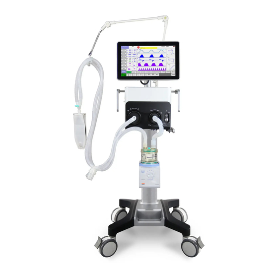
Page 28: Equipment Appearance
2.2. Equipment Appearance 2.2.1 Front View 28 / 182... - Page 29 Caster and brake The ventilator has four casters and all casters have brakes. Humidifier 3 Expiratory water trap Collects condensed water in the expiratory tube. 4. Inspiratory water trap Collects condensed water in the inspiratory tube. Test lung Inspiratory tube Expiratory tube 8 Support arm Supports and hangs the patient tubing.
-
Page 30: Rear View
2.2.2 Rear View Inlet of low-pressure O2 supply Inlet of high-pressure O2 supply AC power receptacle Hang the power cord Main unit air inlet grille Air intake dust filter and Oxygen sensor. VGA connector Outputs VGA video signals with the same contents to the primary display and connects to the external display (supporting display with resolution of 1280*800). - Page 31 CO2 module Mainstream or sidestream CO module for optional configuration. The connector varies depending on the configured module. 10. RS-232 connector Connects to the external calibration device for calibrating pressure. An external medical device can be connected via this connector to communicate with the ventilator. 11.
- Page 32 FOR YOUR NOTES 32 / 182...
-
Page 33: Chapter 3 Installations And Connections
Chapter 3 Installations and Connections WARNING Do not use antistatic or conductive masks or patient tubing. They can cause burns if they are used near high frequency electrosurgery equipment. To ensure optimum performance of the ventilator, re-do System Check each time after accessories or components like patient tubing, humidifier, and filter are replaced. -
Page 34: Connect To The Power Supply
3.2 Connect to the Power Supply 3.2.1 Connect to AC Power A. AC power receptacle B. AC power cord Insert the AC power cord into the AC power receptacle. 34 / 182... -
Page 35: Connect To The Gas Supply
3.3 Connect to the Gas Supply High-pressure O supply connector High-pressure O supply hose and fitting Low-pressure O supply connector D. Low-pressure O supply hose This ventilator provides two types of gas supply connection: high-pressure O and low-pressure O When the ventilator is connected to high-pressure O supply, the normal working gas supply pressure is 280~600KPa. - Page 36 hose. WARNING Inspect the O2 supply connector carefully and ensure there is no leakage. If gas leakage is significant, O2 concentration in the ambient environment will exceed normal O2 concentration in atmosphere, resulting in potentially dangerous O2 enriched environment. ...
-
Page 37: Install The Support Arm
3.4 Install the Support Arm Fixing block knob B. Fixing block C. Tube hook Support arm joint E. Support bar F. Support arm joint Support arm joint Loosen the fixing block knob. Place the fixing block onto the handle on the side of the ventilator. -
Page 38: Install The Patient Tubing
Adjust the support arm. Place the patient tubing onto the tube hook. NOTE Operate support arm joint F or G with both hands as shown below. Operating with a single hand will bring some risks. The maximum weight of the support arm is 1 kg. ... - Page 39 A. Inspiratory filter B. Expiratory filter C. Inspiratory water trap D. Expiratory water trap E. Simulation of lung F. Support arm book Connect the patient to the ventilator via the patient breathing circuit. Mount the filters onto the inspiratory and expiratory ports. Connect the inspiratory filter to the water trap via the tube.
-
Page 40: Install The Humidifier
3.6 Install the Humidifier WARNING To prevent possible patient injury and equipment damage, do not turn on the humidifier until the gas flow has started and is regulated. To prevent possible patient injury and equipment damage, ensure the humidifier is set to appropriate temperature and humidity. -
Page 41: Install The Nebulizer
A. Humidifier B. Humidifier bracket slot C.Humidifier inlet D.Humidifier outlet E. Humidifier mounting plate Align the humidifier mounting plate and the slot, and slide the humidifier in. Tighten the screw. Mount the filters onto the inspiratory and expiratory ports. Connect the inspiratory filter to the humidifier inlet via the tube. Connect the humidifier outlet to the water trap via the tube. - Page 42 A. Nebulizer connector B.Nebulizer tube C. Nebulizer Connect one end of the nebulizer tube to the nebulizer connector and the other end to the nebulizer. Install the nebulizer to the inspiratory limb via the tube. 42 / 182...
-
Page 43: Install The O2 Sensor
3.8 Install the O2 Sensor CAUTION To reduce the risk of explosion, do not burn the O2 cell or force the cell open. A. Main unit air inlet grille sensor C. O sensor connection cable Rotate the O sensor clockwise to install it. Push the O sensor and its fixing seat into the ventilator. - Page 44 FOR YOUR NOTES 44 / 182...
-
Page 45: Chapter 4 User Interface
Chapter 4 User Interface 4.1 Display Controls The control unit is characterized by a small number of operating elements. Its main elements are: Alarm indicator A group of red / yellow color, and includes a translucent lens LED. Provide visual alarm information through different color and different flicker frequency. -
Page 46: Syst.check Screen
Bright: start system. Extinct: system shutdown Up key Alternate user operation key, press this button, the cursor moves upward. Enter key Alternate user operation key, press this button for confirmation. Dwon key Alternate user operation key, press this key to move the cursor down. System on / off key Press this button to start system, long press this button again, pop-up box then select [OK] button, enter the 5S countdown display interface , After countdown system... -
Page 47: Standby Screen
4.3 StandBy Screen Click the [O2 Therapy] button to O2 Therapy ventilation pattern. Patient Type setting Click the [New Patient] button, set the patient type, gender, invasive, noninvasive and patient height. Click the [Previous Patient] button, displays current patient information and invasive or noninvasive ventilation patterns. - Page 48 Ventilation type field Displays Non-invasive or Invasive ventilation type. Soft key field Displays soft keys: Alarm, 100%O2, Nebulizer, Tools, Lock, Freeze,Lock and Menu. StandBy button Click to return to the standby interface Oxygen concentration setting button Set Oxygen concentration .rang:21~100% Ventilation mode field Displays Standby or active ventilation mode and ventilation assist indication.
-
Page 49: Measured Values Screen
Displays waveforms:paw、Volume、Flow、CO2、Pleth. 11. Technical alarm field Displays the technical alarm messages. When there are multiple alarm messages, the number of alarms is displayed. In this case, select the alarm message field, and you can view active alarm messages, alarm occurrence time and alarm level on the accessed window. -
Page 50: History Data
screen as shown below. 4.6 History Data Select the [Menu], select the [Data] button to access the window as shown below. You can view tabular trend, graphic trend, and event logbook in the History window. 4.6.1 Tabular Trend You can view the patient’s monitored parameter data and events under the Tabular Trend tab. -
Page 51: Graphic Trend
4.6.1.1 Navigating in Tabular Trend Button Function Moves the cursor one record back/forward from its current position. Moves the cursor to the top/bottom parameter from its current position. Moves the cursor up/down one page from its current position. Previous Moves the cursor to the previous event from its current position. Event Next Event Moves the cursor to the next event from its current position. - Page 52 4.6.2.1 About Graphic Trend Graphic Trend displays the time and date on the vertical axis. Graphic Trend displays the parameter data on the horizontal axis. Graphic Trend is not stored when the machine is in standby status. ...
-
Page 53: Event Log
4.6.3 Event Log For alarm logbook, the system provides up to 500 events, which are stored in chronological order. When a new event occurs after 500 events are already stored, the new event overwrites the earliest one. Click the bottom [Menu] -> [Data] -> [Alarm Log ], you can enter the trend interface, as shown below: 4.6.3.1 About Event Log... -
Page 54: Big Font Screen
Previous Event Moves the cursor to the previous event from its current position. Next Event Moves the cursor to the next event from its current position. 4.6.3.3 Filter In the Event Logbook window, you can set [Level] to [High Alarms], [Med Alarms], [Low Alarms] and [All Alarms]. -
Page 55: Freeze
4.9 Freeze The freeze function’s feature is that it can pause the real-time refreshing of waveforms and spirometry loops on the screen, so that you can have a close examination of the patient’s status within this time period. The reviewed data are waveforms and spirometry loops in the 30 seconds before entering freeze state. - Page 56 FOR YOUR NOTES 56 / 182...
-
Page 57: Chapter 5 System Settings
Chapter 5 System Settings 5.1 Display Settings 5.1.1 Interface Select [Menu]→[System Setting]→[Setting]. Set [Layout] as required to select the type of interface you want to display. 【Normal】: Display the main interface. 【Big Font】: Display large font interface. [All Params]: display the full parameter monitoring interface. -
Page 58: Adjust Screen Brightness
5.4 Adjust Screen Brightness Select [Menu]→[System setup]→[Setting]. Select [Day] or [Night] to choose the corresponding default screen brightness. On the screen backlight brightness setting, select [Menu] → [System Setup] → [Other]. 【Day】 : 【Back Light】 defaults to 6, 【Back Light】 range of 0 ~ 9, the user can set the brightness as needed. -
Page 59: Set 100%O2 Active Time
Select [Language] and select the desired language. Restart the ventilator to activate the selected language. 5.11 Set 100%O2 Active Time Select [Menu]→[Factory setting]→enter the required password→[Setting setup]. Select [100%O2 Active Time] among 2min and 3min. [2min]:100%O2 straight for 2 minutes. ... -
Page 60: Set O2 Compensation
Select [Menu] → [System setup] → [CO2 module]. 【CO Unit】: 【mmHg】, 【Kpa】, 【%】, the default is 【mmHg】. 5.14.3 Set O2 compensation Select [Menu] → [System setup] → [CO2 module]. 【O2 Compen】: 【Low】, 【Mid】, 【High】, the default is 【Low】. 5.14.4 Set N2O compensation Select [Menu] →... -
Page 61: Set Peep
5.17.2 Set PEEP Select 【VC-ACV】 、 【PC-ACV】 、 【PVC-ACV】 、 【VC-SIMV】 、 【PC-SIMV】 、 【PVC-SIMV】 、 【PC-Dual PAP】 、 【PC-APRY】 、 【CPAP/PSV】 or 【CPAP-VG】 ->【PEEP】soft key. Popup the prompt setting window,use your finger presss the frame and slide to the right,... -
Page 62: Set Tinsp
Popup the prompt setting window,use your finger presss the frame and slide to the right, the value gradually increase; slide to the left, the value gradually reduce; or long 】and no release,the value gradually increase;long press【 】and no press【 】or【 】release,the release,the value gradually reduce;also you can press【... -
Page 63: Set Trigger
value increaseor reduce one step length.Set【Texp】to the appropriate value. 】to confirm your setting take effect;press【 】cancel setting and not Press【 take effect. 5.17.9 Set Trigger Select 【 VC-ACV】 、 【PC-ACV】 、 【PVC-ACV】、 【VC-SIMV】 、 【PC-SIMV】 、 【PVC-SIMV】 、 【PC-Dual PAP】 、 【PC-APRY】 、 【CPAP/PSV】 or 【CPAP-VG】 ->【Trigger】soft key. -
Page 64: Set Tpause
】to confirm your setting take effect;press【 】cancel setting and not Press【 take effect. 5.17.12 Set Tpause Select【VC-ACV】or【VC-SIMV】->【Tpause】soft key. Popup the prompt setting window,use your finger presss the frame and slide to the right, the value gradually increase; slide to the left, the value gradually reduce; or long 】and no release,the value gradually increase;long press【... -
Page 65: Set Thigh
Select【PC-Dual PAP】->【Plow】soft key. Popup the prompt setting window,use your finger presss the frame and slide to the right, the value gradually increase; slide to the left, the value gradually reduce; or long 】and no release,the value gradually increase;long press【 】and no press【... -
Page 66: Restore Factory Default Settings
groups of default settings, adult and pediatric, based on patient type. Current settings. You can change the ventilator’s default settings based on the current settings during ventilation and save the changed settings as default settings. There are two groups of default settings, adult and pediatric. ... -
Page 67: Chapter 6 Ventilation
Chapter 6 Ventilation 6.1 Turn on the System Insert the power cord into the power receptacle. Ensure the external power indicator light is lit. Press the key. The alarm indicator light flashes yellow and red once in turn, and then the speaker and the buzzer give a check sound respectively. -
Page 68: Select Patient
The system check screen displays the last system check time. Select the [Details] button to query the system check information of the ventilator system, including system check items, System Check results, and System Check time. Connect the gas supply and block the Y piece as illustrated. Then select [Continue] to start System Check item by item. -
Page 69: Ventilation Type
After System Check is completed, select [Continue] to enter Standby status. Then select patient. If you select [Previous Patient], set ventilation type in the accessed screen, and then select [StartVentilation]. If you select [New Patien], set gender, [Height], ventilation type in the accessed screen, and then select [Start Ventilation]. -
Page 70: Set Ventilation Type
ventilation mode. CAUTION Do not use NIV on patients with no or irregular spontaneous breaths. NIV is intended to provide supplemental ventilatory support to patients with regular spontaneous breaths. Do not attempt to use NIV on intubated patients. 6.4.3 Set Ventilation Type To set ventilation type, If the ventilator is in non-standby mode, press the [Standby] key and enter Standby... -
Page 71: Apnea Ventilation
Parameter setup quick key field Displays ventilation setting parameters corresponding to the active ventilation mode. Selecting displays more ventilation setting parameters. The parameters of sigh function, ATRC function, Apnea Vent and other parameters are also set here. Ventilation parameters vary subject to the ventilation mode. 6.5.2 Apnea Ventilation Apnea ventilation is a backup ventilation mode initiated when the ventilator detects patient apnea in CPAP/PSV and CPAP-VG modes. - Page 72 rate(RR). In VC-ACV mode, you need to set the following ventilation parameters: [Pmax]: Can prevent high airway pressure caused by patient [PEEP]: Positive end-expiratory pressure [Vt]: Tidal volume [I:E]: Inspiration tiem [Rate]: Breathing frequency [Tpause]: Percent of inspiratory pause time [Trigger]: Inspiration trigger level Oxygen concentration.
-
Page 73: Pc-Acv
[Disable ATRC]: Switch off ATRC function [ET Tube]: Endotracheal tube [Trach Tube]: Tracheal tube [Tube I.D.]: Diameter of tube [Compensate]: Compensate portion [Expiration]: Compensate of expiration In VC-ACV mode,you can set the other function parameters as required in Invasive ventilation (this function is applied to all Invasive modes and the description is not repeated in the other ventilation modes section in this manual.) : [Compliance Compensate]... -
Page 74: Pvc-Acv
In PC-ACV mode, you need to set the following basic ventilation parameters: [Pmax]: Can prevent high airway pressure caused by patient [PEEP]: Positive end-expiratory pressure [Pinsp]: Inspiration pressure [I:E]: Inspiration time [Rate]: Breathing frequency [Tslope]: Time of pressure rising [Trigger]: Inspiration trigger level Oxygen concentration In PC-ACV mode, you can set the following sigh function parameters as required:... - Page 75 guaranteed to be equal to the preset tidal volume. Ppeak will vary according to the tidal volume setting and the resistance and compliance of the patient’s lungs. Pressure adjustment increase of the ventilator cannot exceed 10 cmH2O for the first 3 cycles, and cannot exceed 3 cmH2O for each of the following cycles.
-
Page 76: Vc-Simv
[Trigger]: Inspiration trigger level Oxygen concentration In PC-ACV mode, you can set the following sigh function parameters as required: [Sigh]: Switch for turning on sigh function [Interval]: Number of sigh cycles [Delta Pinsp]: Pinsp added in sigh cycle 6.5.6 VC-SIMV VC-SIMV (Volume Controlled–Synchronized Intermittent Mandatory Ventilation) is a ventilation mode in which the ventilator controls the ventilation, but it can be influenced by the patient. -
Page 77: Pc-Simv
In VC-SIMV mode, you need to set the following basic ventilation parameters: [Pmax]: Can prevent high airway pressure caused by patient [PEEP]: Positive end-expiratory pressure [Psupp]: Pressure support leve [Vt]: Tidal Volume [Tinsp]: Inspiration time [Rate]: [Tslope] Breathing frequency [Trigger]: Inspiration trigger level [Exp%]: Expiration trigger level... -
Page 78: Pvc-Simv
In PC-SIMV mode, you need to set the following basic ventilation parameters: [Pmax]: Can prevent high airway pressure caused by patient [PEEP]: Positive end-expiratory pressure [Psupp]: Pressure support leve [Pinsp]: Inspiration pressure leve [Tinsp]: Inspiration time [Rate]: [Tslope] Breathing frequency [Trigger]: Inspiration trigger level [Exp%]:... - Page 79 PRVC breath is also delivered once if it is not triggered at the end of trigger window. Spontaneous breathing or pressure support breathing is supported outside the trigger window. The following figure shows typical waveforms in PRVC -SIMV+PSV mode. In PVC-SIMV mode, you need to set the following basic ventilation parameters: [Pmax]: Can prevent high airway pressure caused by patient...
-
Page 80: Pc-Dual Pap
6.5.9 PC-Dual PAP PC-DualPAP (Pressure Controlled– Synchronized Intermittent Mandatory Ventilation Dual PAP)is a ventilation mode in which the ventilator controls the ventilation, but it can be influenced by the patient. It is also known as PC-BIPAP, DuoPAPorBiLevel ventilation. The inspiration and expiration are pressure controlled. The patient can breathe spontaneously during inspiration and expiration. -
Page 81: Pc-Aprv
[Trigger]: Inspiration trigger level [Exp%]: Expiration trigger level [Tslope]: Time of pressure rising 10. [O Oxygen concentration In PC-Dual PAP mode, you can set the following apnea vent function parameters as required: [Apnea Vent]: Switch for turning on apnea vent function [Apnea Vt]: Tidal volume in apnea ventilation [Apnea Rate]: Frequency of apnea ventilation... -
Page 82: Cpap/Psv
In PC-APRV mode, you need to set the following basic ventilation parameters: [Pmax]: Can prevent high airway pressure caused by patient [PEEP]: Positive end-expiratory pressure [Pinsp]: Inspiration pressure leve [Tinsp]: Inspiration time [Texp]: Expiration time [Trigger]: Inspiration trigger level [Tslope]: Time of pressure rising Oxygen concentration In PC-APRV mode, you can set the following apnea vent function parameters as required:... -
Page 83: Cpap-Vg
) is a ventilation mode in which the patient breathes spontaneously. This is possible because it is a pressure controlled mode. In CPAP/PSV, with no options activated, the ventilator does not deliver any mandatory or triggered breaths. The spontaneous breathing phases (inspiration and expiration) are detected with by using inspiratory and expiratory phase recognition, using a flow level detector. -
Page 84: Start Ventilation
You can set the alarm limits for Paw、PEEP、MVe、Rtotal、VTi mand、FiO2 and Tapnea by pressing the [Alarm] key and selecting alarm limits in the accessed menu. You can set EtCO alarm limits if your ventilator is configured with CO module. You can also set alarm volume . For details, refer to 10 Alarms. - Page 85 PEEP Positive end-expiratory pressure. Setting parameter Description Plow Plow is the low pressure level at which the patient can breathe spontaneously. Phigh Phigh is the high pressure level at which the patient can spontaneously breathe and is an absolute value. Pinsp It is a relative value of the pressure, relative to PEEP.
- Page 86 Exp.Speed It is the expiratory compliance compensate speed. Monitored parameter Description Ppeak The maximum pressure value in one breathing cycle. Pplat The airway pressure during inspiratory pause. Pmean The mean pressure value in one breathing cycle. PEEP Positive end-expiratory pressure. The inspired tidal volume in one cycle.
-
Page 87: Enter Standby Status
Rapid shallow breathing index - quotient between fspn and TVe RSBI spn (measured in liters). Ptracheal Pressure tracheal. Poutput Pressure output. Pambieat Pressure ambieat. The percentage of oxygen in the patient’s inspired gas. FiO2 FiO2 Cal Oxygen concentration calculation shows values FiO2 measu Oxygen concentration monitoring actual value EtCO2... - Page 88 FOR YOUR NOTES 88 / 182...
-
Page 89: Chapter 7 Co 2 Monitoring
Chapter 7 CO Monitoring 7.1 Summary The carbon dioxide monitor are used during respiratory Ventilator therapy, for patient gas monitoring, used in adults, children, babies. CO2 module using the principle of gas having absorption characteristics with infrared to measure the gas concentration.All the gases that can be measured by the module can absorb the infrared and each gas has it’s own absorption characteristics.The gas sent to a sampling room ,infrared filter select a particular band infrared thread the gas.If measure with several gases, then it will have a number of infrared filter.In a given volume,the higher the gas... -
Page 90: Side Stream
Use only with IRMA monitor supporting MASIMO airway adapter. After IRMA adult / child model airway adapter access to circuit will increase 6mL of dead space, and therefore prohibited for infants. Do not use IRMA infant airway adapter for adults, otherwise it will lead to excessive flow resistance. -
Page 91: Set Co2
To avoid cross-infection, do not reuse disposable sampling tube. The used disposable sampling tube should be disposed according to local medical waste disposal regulations. Do not through Nomoline sampling tube apply negative pressure (such as using a syringe) to remove condensate. - Page 92 with the module interface cable on the backboard of the ventilator; Install IRMA probe to the airway adapter,the probe buttoned means installed correctly; Connect the 15mm male adapter of the airway adapter to the connection port of the patient Y-shaped tube of breathing circuit; Connect the 15mm female adapter of the airway adapter to the patient’s endotracheal tube;...
-
Page 93: Checking Before Using
Press the start key to start the system, in the beginning the LED on probe flashes, probably about 10 seconds later turn to normally green. AG module defaults to standby mode, when connected AG module,the screen will display 【AG is sleeping】. Click【Menu】hot key->【System Setup】->【CO2 module】;【Operating Mode】select 【Measure】,the screen display【AG is starting】. -
Page 94: Monitor Calibration
Factors affecting the monitoring accuracy of mainstream gas monitor to, including: Quantitative effects of humidity or condensation; Quantitative effects of atmospheric pressure; Interfering gases or water vapor; Other interference sources. 7.3.4 Monitor calibration In the following situations Main stream Anesthetic gas module (IRMA AX+) 、 Main stream CO2 module(IRMA CO2)should be calibrated to zero: ... -
Page 95: Module Cleanliness
in time: Display mode Statements Green light no twinkle System OK Green light twinkle Calibrating Blue light no twinkle Exist anesthetic gas Red light no twinkle Sensor error Red light twinkle Check the adapter Note1:Only apply to IRMA AX+ main stream anesthetic gas module. 7.3.6 Module cleanliness Allow to clean the probe. -
Page 96: Checking Before Using
Press the system switch button,start the system; After LED flash on ISAmonitor flashed sereval seconds turn to normally on means mearuring state. Sidestream module defaults to standby mode, when connected sidestream module,the screen will display【AG is sleeping】。 Click 【Menu】 -> 【System Setup】 -> 【Gas Module】 : select 【 Measure】 ,the screen display 【AG is starting】. -
Page 97: Affecting Factors Of Monitoring
7.4.3 Affecting factors of monitoring Effects of atmospheric pressure Use the percentage of the volume as the unit to reporte the gas concentration, at this time the measurement results are not affected by atmospheric pressure. Concentration is defined as follows: %gas=Partial pressure of gas component/Total pressure of gas mixture*100. -
Page 98: Module Calibration
EtCO2(BTPS)= EtCO2*(1-(3.8/pamb)) Of which:EtCO2=from ISA delivered EtCO2 value[Vol%] pamb=from ISA delivered atmospheric pressure [kPa] 3.8= typical partial pressure between the patient circuit and the water vapor of condensed water of ISA [kPa] EtCO2(BTPS)= EtCO2 value[Vol%] under BTPS Assumed to have been calibrated the O2 using the room air in 0.7Vol% H2O humidity level. 7.4.4 Module calibration ISA marginalia gas analyzer with automatic zero calibration function, no need the user to operate. -
Page 99: Compensation
Allow do regularly cleaning for the monitor. To avoid dust or cleaning liquid through LEGI interface enter the monitor, during the cleaning process should always make sure Nomoline sampling tube is connected with the monitor. When cleaning the monitor, first use the damp cloth that soaked in the highest concentration of 70% of medical alcohol to wipe clean the probe, at last, with a dry lint-free cloth to dry it. - Page 100 FOR YOUR NOTES 100 / 182...
-
Page 101: Chapter 8 Spo2 (Optional)
Chapter 8 SpO2 (optional) 8.1 Overview Blood oxygen saturation (SpO2) is the percentage of oxyhemoglobin (HbO2) capacity bound by oxygen in the blood in the total hemoglobin (Hb) capacity that can be combined, that is, the concentration of oxygen in the blood. The principle for monitoring the pulse SpO2 is to fix the probe fingerstall on the patient’s finger, use the finger as a transparent container for hemoglobin, use 660nm wavelength red light and 880nm near-infrared light as the incident light, maximum output power is 300 mw, measure the... -
Page 102: Monitoring Steps
Do not put the sensor on limbs with arterial duct or intravenous tube. Do not intertwine electrosurgical equipment cable with the sensor cable. Avoid using the monitor and sensors while using the NMR equipment, in order to avoid severe burns to the patient as a result of induced currents. -
Page 103: Setting Spo2
Fig. 8-1 SpO2 Parameter Area Setting SpO2 Select SpO2 parameter area or Pleth wave area → [SpO2 Setup] menu, which is shown below. You can set SpO2 through [SpO2 Setup] menu. Fig. 8-2 [SpO2 Setup] Menu 8.5.1 Setting Wave Speed ... -
Page 104: Measuring Influencing Factors
time, the slower the monitor responds when the patient's SpO2 value changes, but the measurement accuracy is higher. In monitoring critically ill patients, a smaller average time is conducive to timely analysis of the disease. The setting method follows: Select [Avg.Time] to set the average time to [2s], [3s], [4s], [5s], [6s], [7s] or [8s]. -
Page 105: Chapter 9 Special Functions
Chapter 9 Special Functions 9.1 Manual Breath Select the [Tools] key→[Functions]→[Manual Breath], and the ventilator system delivers a breath to the patient based on the current ventilation mode. NOTE Manual breath is disabled in Standby status. Pressing the [Manual Breath] key during inspiratory phase cannot initiate a manual breath. -
Page 106: Nebulizer
Inspiration Hold function is disabled in Spn-CPAP mode and is supported when apnea ventilation occurs. There is at least one expiratory phase between two inspiration holds. The system responds to Insp. Hold key pressing operation only in non-standby status. 9.4 Nebulizer During nebulization, aerosolized medicament is inhaled by the patient for the purpose of therapy. -
Page 107: P0.1
When O2 supply type is low-pressure, pressing the [100%O2] key will not activate oxygen enrichment, rather display the prompt message [Fail to Start with Low Pressure O2 Supply]. 100%O2 (oxygen enrichment) is disabled in Standby status. Removing the patient tubing during oxygen enrichment will start suction function. Refer to section 9.6 Suction. -
Page 108: Switching On O2 Therapy
9.7.1 Switching on O2 Therapy WARNING The device must only be used under the supervision of qualified medical staff, so that help is immediately available if malfunctions occur or the patient has insufficient spontaneous breathing. Select the [Standby] key to enter Standby status after confirmation. Select [O Therapy] in the Standby status to enter O therapy screen. -
Page 109: Switching Off O 2 Therapy
Enter the number of timing minutes in [O Therapy Time Setup] to start the timer. When the set time expires, the system gives prompt sound and O supply is not interrupted. 9.7.4 Switching off O Therapy During O therapy, select the [Standby] key to enter Standby status after confirmation, so as to switch off the O therapy function. -
Page 110: Chapter 10 Alarms
Chapter 10 Alarms 10.1 Summary Alarms, triggered by a vital sign that appears abnormal or by technical problems of the ventilator, are indicated to the user by visual and audible alarm indications. NOTE When the ventilator is started, the system detects whether audible alarm tones and alarm lamp function normally. -
Page 111: Alarm Level
10.1.2 Alarm level According to the severity of the alarm, the physiological alarm of the ventilator can be divided into advanced alarm, secondary alarm and low level alarm. High Priority alarm The patient is in critical condition, and may have life risk, should be an immediate rescue. -
Page 112: Alarm Information
Audible alarm refers to when the alarm occurs, ventilator adopts different voice characteristics to indicate different levels of the alarm. High priority alarm:the speaker gives out rhythmic sound prompt,i.e.the “beep-beep-beep--beep-beep----beep-beep-beep--beep-beep”,of a cycle in about 10s; Medium priority alarm:the speaker gives out continuous sound prompt,i.e.the “beep-beep-beep”,of a cycle in about 25s;... -
Page 113: Parameters Scintillation
10.2.4 Parameters scintillation When the alarm of parameters which are for monitoring the patients such as monitoring EtCO2, FiCO2, awRR, the parameter value will blink once per second frequency, high limit or lower limit of the parameter will also be the same frequency flashing, indicating that the parameter exceeds the upper limit or a low limit. -
Page 114: Alarm Tests
CAUTION In case that high pressure alarm limit of 60 cmH2O is not required under clinical condition, setting high pressure alarm limit to 60 cmH2O or less is recommended so as to extend the service life of the turbine and the battery. NOTE ... -
Page 115: Paw Too Low
10.6.3 Paw Too Low After the ventilator system starts up normally, connect a test lung to the ventilator and start ventilation. Set Paw low alarm limit to current Peak. Squeeze the test lung hard during inspiration. Verify that the [Paw Too Low] alarm is activated, the ventilator cycles into expiration, and airway pressure falls to PEEP level. -
Page 116: Peep Too High
10.6.9 PEEP Too High After the ventilator system starts up normally, connect a test lung to the ventilator and start ventilation. Set the PEEP high alarm limit to be greater than the current PEEP. Verify that the [PEEP Too High] alarm is activated. 10.6.10 PEEP Too Low After the ventilator system starts up normally, connect a test lung to the ventilator and start ventilation. -
Page 117: Fio2 Too Low
Set the FiO high alarm limit to be less than the current O concentration monitored value after ventilation is stable. Verify that the [FiO Too High] alarm is activated. 10.6.15 FiO2 Too Low Connect the ventilator to high-pressure O supply. Connect a test lung to the ventilator and start ventilation. -
Page 118: Awrr Too High
Verify that the [FiO2 Too High] alarm is activated. 10.6.19 awRR Too High Connect a test lung to the ventilator and start ventilation. Connect the CO2 test module. Select the [Menu] key → [System setup] → [CO2 Module] to set [Operating Mode] to [Measure]. Set the awRR high alarm limit to be less than the current awRR. -
Page 119: Prtoo Low
10.6.24 PRToo Low Connect a test lung to the ventilator and start ventilation. Connect the SPO2 test module. StandBy state.Select the [Menu] → [Factory Setting], input password (112358) → [SPO2 Module] to set SPO2 Type]. Set the PR low alarm limit to be greater than the current PR. Verify that the [PR Too Low] alarm is activated. -
Page 120: Alarm Information Table
10.8 Alarm information table 1) Alarm information includes physical and technical alarm information, but some alarm information is not necessarily listed. 2) Column P stands for the default alarm level: H for high, M for medium and L for low. 3) For each alarm message, list all the corresponding countermeasures. - Page 121 The TVe monitored value is less than TVe low alarm limit for continuous 3 mechanical ventilation cycles. 1. Check the patient. TVe Too Low 2. Check the ventilation parameter setup. 3. Check the alarm limits. 4. Check the patient tubing for leakage or occlusion. 5.
-
Page 122: Technical Alarm
1. Check the patient type. 2. Check the alarm limits. The time of failure to detect respiration by the CO module exceeds Apnea Tinsp. Apnea CO 1. Check the patient. 2. Check apnea time setup. 3. Check the connections of CO module sampling device. - Page 123 Exhalation flow rate trigger. Exp. Flow Trigger 1. Check the patient. 2. Check ventilation settings. In volume mode or pressure mode when ATRC function is enabled, the pressure reaches Paw high alarm limit-5. Pressure Limited 1. Check the patient. 2. Check the ventilation parameter setup. 3.
- Page 124 Supply Failure 1. Check connection with O2 supply. 2. Check O2 supply pressure. CO2 module communication stopped 1. Check if the module is faulty. CO2 communication 2. While removing the ventilation module, unplug the stopped CO2 module. 3. Please contact your designated service representative. Parameter measured values exceed the measurement range (error range is included).
- Page 125 FOR YOUR NOTES 125 / 182...
-
Page 126: Chapter 11Cleaning And Disinfection
Chapter 11Cleaning and Disinfection WARNING Obey applicable safety precautions. Read the material safety data sheet for each cleaning agent. Read the operation and service instructions for all disinfection equipment. Wear gloves and safety glasses. A damaged O2 sensor can leak and cause burns (contains potassium hydroxide). -
Page 127: Methods For Cleaning And Disinfection
After cleaning and disinfection is completed, run System Check before using the equipment. Use the equipment only when System Check is passed. The expiration valve assembly, inspiration safety valve assembly, and patient hose of the gas pathways through the ventilator can become contaminated with body fluids and expired gases during both NORMAL CONDITION and SINGLE FAULT CONDITION. - Page 128 Patient tubing (including water trap, ② B or C Each patient/weekly Y piece, adapter) Other Refer to the cleaning and Mainstream CO sensor Each patient/weekly disinfection methods provided by the mainstream CO vendor. SPO2 Probe Each patient/weekly Refer to the cleaning and disinfection methods provided by theSPO2 vendor.
-
Page 129: Disassemble The Ventilator's Cleanable And Disinfectable Parts
Glutaraldehyde (2%) Highly efficient disinfectant Ortho-Phthalaldehyde disinfectant (such as Highly efficient disinfectant ® Cidex OPA) Soap water (pH value of 7.0~10.5) Rinsing agent Clean water Rinsing agent Steam autoclave* Highly efficient disinfection Steam autoclave*: The recommended temperature of this disinfection method is 134º... -
Page 130: Inspiration Safety Valve Assembly
To install the expiration valve assembly: Install the expiration valve membrane onto the expiration valve assembly. According to direction of rotation, Then rotate the expiration valve handwheel clockwise (and depress the handwheel in the direction the expiration valve is installed) until the knob to tight. - Page 131 Push the inspiration safety valve assembly into the corresponding connector on the ventilator horizontally to the end. According to direction of rotation, Then rotate the expiration valve handwheel clockwise (and depress the handwheel in the direction the expiration valve is installed) until the knob to tight.
-
Page 132: High Efficiency Particle Air (Hepa) Filter Assembly And Dust Filter
Align the guides on membrane fixing knob with the grooves of safety valve body. Insert the membrane fixing knob, press it tightly and rotate it clockwise to the end position. 11.2.3 High Efficiency Particle Air (HEPA) Filter Assembly and Dust Filter A. -
Page 133: Patient Tubing
NOTE Install the specified HEPA filter and air intake dust filter. CAUTION Do not run the ventilator if the ventilator is not equipped with HEPA filter to avoid contaminating the ventilator inspiration port and patient tubing. 11.2.4 Patient Tubing WARNING ... -
Page 134: Nebulizer
A. Inspiratory filter B. Expiratory filter C. Inspiratory filter D. Expiratory filter E.Heat&Moisture Exchange(HME) To disassemble the patient tubing: Pull out the patient tubing one by one. To install the patient tubing: Mount the filters onto the inspiratory and expiratory ports. Connect the inspiratory filter to the water trap via the tube. - Page 135 A. Nebulizer connector Nebulizer tube C. Nebulizer To disassemble the pneumatic nebulizer: Pull out the nebulizer tube from the nebulizer connector. Pull out the nebulizer tube from the nebulizer and remove the nebulizer. To install the pneumatic nebulizer: Connect one end of the nebulizer tube to the nebulizer connector and the other end to the nebulizer.
-
Page 136: Humidifier
11.2.6 Humidifier NOTE The humidifier shall comply with the requirements of ISO 8185. The humidifier assembly, its installation and disassembling steps described in this section are only for reference. 11.2.6.1. Humidifier on the Ventilator 136 / 182... - Page 137 A. Humidifier Humidifier mounting plate Humidifier bracket slot D. Screw Humidifier inlet Humidifier outlet To disassemble the humidifier from the ventilator: Disconnect the tubes from the humidifier. Remove the screw. Lift up the humidifier to remove it from the humidifier bracket fixed seat. ...
-
Page 138: Mainstream Co2 Sensor
11.2.7 Mainstream CO2 Sensor A. CO2 sensor B. CO2 airway adapter To disassemble the CO sensor: Pull out the CO sensor vertically. To install the CO sensor: Fix the CO sensor on the CO airway adapter vertically. 138 / 182... -
Page 139: Chapter 12 Maintenance
Chapter 12 Maintenance 12.1 Repair Policy WARNING Obey infection control and safety procedures. Used equipment may contain blood and body fluids. Movable parts and removable components may present a pinch or a crush hazard. Take care to move or replace system parts and components. ... - Page 140 Replace the expiration valve if it is damaged Expiration valve (refer to 11.2.1). calibration Calibrate the CO module when the CO measured value has a great deviation. Touch screen Calibrate the touch screen if its function is degraded. Several times a Patient tubing Check the patient tubing and water traps for water day or as...
-
Page 141: Pressure And Flow Zeroing
Backup alarm system Check the alarm duration of backup alarm system (buzzer). If it is too short, contact us. Gas source sealing ring Check the gas source sealing ring. Contact us for replacement if necessary. Expiration valve membrane Check the expiration valve membrane. Contact us for replacement if necessary. -
Page 142: Oxygen Concentration Calibration
displayed. During the calibration, if you select [Stop], the ongoing calibration will stop and the message [Calibration Stopped! Calibration is unfinished.] is displayed. After a successful calibration, the screen shows [Calibration Completed!]. Otherwise, the message indicating calibration failure is displayed. In this case, you need to do the calibration again. -
Page 143: Co2 Calibration
personnel or us. Handle and dispose of the O2 sensor according to your biohazard policies. Do not incinerate. Oxygen concentration monitoring does not provide automatic atmospheric pressure compensation. Do oxygen concentration calibration again when atmospheric pressure has changed. ... -
Page 144: Battery Maintenance
Press the [Menu] key. Select [System setup] and select [Others]. Select [Cal.Touchsereen]. mark appears in different locations of the screen. Click the central point of one by one. After the calibration, the button [OK],[Cancel] and [Retry] is displayed. Select [Ok] to complete the calibration. 12.8 Battery Maintenance CAUTION ... -
Page 145: Battery Performance Conditioning
The battery power is low, need to be charged immediately, otherwise the device will automatically shut down. Battery is not installed The battery is normal, in a state of charge. If the capacity of the internal battery is limited, the alarm [Battery Low] will be triggered. In this case, apply external power to the ventilator. -
Page 146: Battery Performance Checking
12.8.2 Battery Performance Checking Check battery performance once every six months. Checking battery performance is also required before ventilator repair is carried out or when battery is doubted to be the source for ventilator failure. Battery performance may degrade over time. Follow these steps to check battery performance: Disconnect the patient from the ventilator and shut down the ventilator. -
Page 147: Battery Recycling
NOTE Remove the batteries from the equipment if the equipment is not used for a long time. Long-time storage of batteries above 38℃ (100℉) greatly shortens the battery life expectancy. 12.8.4 Battery Recycling If obvious signs of damage are detected on the battery or the battery recharging is failed, replace the battery and recycle it properly. -
Page 148: Water Build-Up In The Flow Sensor
tral; and reverse polarity with open neutral. Verify the maximum leakage current does not exceed 500 μA (0.5 mA) in the first two tests. While for the last two tests, verify that the maximum leakage current does not exceed 1000 μA (1 mA). - Page 149 FOR YOUR NOTES 149 / 182...
-
Page 150: Chapter 13 Accessories
Chapter 13 Accessories WARNING The user shall buy legally launched products for other accessories required to implement the functions of the machine. Use only accessories specified in this chapter. Using other accessories may cause incorrect measured values or equipment malfunction. ... - Page 151 Power cable 040-000101-00 Power cable(0A,125V/3m) Battery 022-000002-00 Li-ion battery, 4800mAh 11.1V) Humidifier kit (including humidifier, water tank, heated patient tubing, etc.) Humidifier kit 022-000102-00 Gas supply hose assembly 022-000302-00 Ventilator oxygen hose accessories kit The pulse oximeter probes and probe cable extenders listed for this device have been validated and tested for compliance with ISO 80601-2-61.
-
Page 152: Chapter 14 Theory Of Operation
Chapter 14 Theory of Operation 14.1 Pneumatic System 14.1.1 Pneumatic Circuit Diagram 14.1.2 Parts List Symbol Description Symbol Description Low-Pressure PZTV1 Air supply (low pressure) Zeroing three-way valve Inlet Dust filter (Air) Inspiratory pressure sensor Inspiratory pressure sensor HEPA filter (Air) filter Humidifier Humidifier... -
Page 153: Theory
High-Pressure supply(high pressure) Nebulizer switch Inlet Filter (O Nebulizer resistor Regulator Nebulizer Nebulizer PSOL Proportional solenoid valve Water trap Bacteria filter (connecting to Filter screen inspiratory port) Flow sensor Expiratory flow sensor Level 1 mixed noise Bacteria filter (connecting to reduction chamber patient port) Filter... - Page 154 for a period of time, dust or foreign substance absorbed on the surfaces of the two filters at the Air inlet can occlude the Air inlet when the dust or foreign substance is accumulated to a certain extent. This may cause insufficient Air intake of the machine and compromise the ventilation performance of the machine.
- Page 155 Check valve (CV3) prevents patient’s expired gas from polluting the components in the upstream of this valve under the single fault condition of expiratory limb being occluded. Safety valve (SAV) ensures that the pressure in the inspiratory limb is kept within the safe range and provides flow to the spontaneous inspiratory channel when the system is powered down.
- Page 156 FOR YOUR NOTES 156 / 182...
-
Page 157: Chapter 15 Product Specifications
Chapter 15 Product Specifications The ventilator is already integrated with expiratory volume monitor, pressure measurement device, and pressure release device. It is equipped with alarm system, O monitor and CO monitor, where: The expiratory volume monitor, pressure measurement device, and pressure release device comply with ISO 80601-2-12. -
Page 158: Power Requirements
Degrees of protection provided by enclosures(IP Code)—IP21 Protection Index according the EN 60529 standard: Degree of protection against 2: Protected against solid foreign objects of 12.5 mm diameter harmful ingress of water and greater 1: Protected against vertically falling water drops Electrical connections between Non-electrical connections the equipment and the patient... -
Page 159: Physical Specifications
Tinsp : 2 s ; Tslope:1.0s; Trigger:0.5L/min; O2% : 21 Vol.% ; R: 20 cmH2O/L/s ; C: 20 ml/cmH2O ; Gas supply nominal work pressure : 400±100 kPa. 15.4 Physical Specifications System noise ) ≤47 dB(A) A-weighted sound pressure level (L System noise... -
Page 160: Pneumatic System Specifications
Audio indicator Gives off alarm tones and key tones; supports multi-level tone Speaker modulation. The alarm tones comply with the requirements of IEC60601-1-8. Buzzer Gives off auxiliary audio alarm in case of speaker malfunction. Connector A connector which supports connection with a PC to perform software Network connector upgrade and connection with external medical and information device. - Page 161 Inspiration module ≥210 L/min(BTPS) Peak flow in case of single Pneumatic medicament Synchronous with inspiration at 6 to 9 L/min flow nebulizer connector Safety valve release pressure <125 cmH Inspiratory outlet (To patient Coaxial 22 mm/15 mm conical connector port) Expiration module Expiratory outlet (From Coaxial 22 mm/15 mm conical connector...
-
Page 162: Ventilator Specifications
Leakage Not greater than 200 mL/min@50 cmH O (adult tubes) Not Leakage greater than 100 mL/min@40 cmH O (pediatric tubes) Not greater than 50 mL/min@20 cmH O (infant tubes) 15.6 Ventilator Specifications Ventilation mode VC-ACV、PC-ACV、PVC-ACV、VC-SIMV、PC-SIMV、PVC-SIMV、 PC-Dual PAP、PC-APRV、CPAP/PSV、CPAP-AG Controlled parameters Parameter Range Unit Accuracy... - Page 163 Pmean -5 to +105 mbar ± (2 + 4% of actual) Pplat -5 to +105 mbar ± (2 + 4% of actual) PEEP 0 to 40 mbar ± (2 + 4% of actual) Ptracheal -10 to 110 mbar ± (5 + 10% of actual) Poutput -10 to 110 mbar...
- Page 164 greater than the -4 to 97 1mbar Low limit lower limit. 1 to 40 1mbar High limit PEEP 0 to 39 1mbar Low limit Adu:0.2 to 100.0 High limit Ped:0.2 to 60.0 0.1L/min Neo:0.2 to 40.0 Adu:0.1 to 99.9 Low limit Ped:0.1 to 59.9 0.1L/min Neo:0.1 to 39.9...
-
Page 165: Special Functions
15.7 Special Functions Function Specification Inspiration Hold Push and hold the Insp. Hold key to activate this function. Inspiration Hold is active for a maximum of 30s. Expiration Hold Push and hold the Exp. Hold key to activate this function. Expiration Hold is active for a maximum of 30s. -
Page 166: Co2 Module Specifications
15.8 CO2 Module Specifications standard ISO 80601-2-55 type Plug and play Measurement sidestream(Masimo ISA CO2), mainstream(Masimo IRMA CO2) model sidestream:<10s(Concentrations reported and full accuracy) Preheating time mainstream :<30s sidestream:<3s(sampling pipe length:2m) Total response mainstream :≤3s time sidestream(50mL/min flow speed):CO2:≤200ms Pressure risetime mainstream (10L/min flow speed):CO2:≤90ms Sampling flow sidestream:50±10mL/min... - Page 167 average value is updated every breath. disposableadult/pediatric: Airway adapter under 6mL is invalid pressure is lower than 0.3cmH2O Only in the 4.5~5.5VDC, voltage fluctuation. Otherwise may lead to incorrect Power input measurments or monitor damaged. sidestream:33X78X49mm,130g(with cable) Size and weight mainstream :38X37X34mm,<25g(without cable)...
-
Page 168: O2 Sensor Specifications
EtCO2 alarm upper limit 0.0~( upper limit-0.1)%(V/V) 0.1 %(V/V) ( lower limit+1)~120 awRR alarm upper limit 1bpm awRR alarm lower limit 0~( upper limit-1) 1bpm 15.9 O2 Sensor Specifications Oxygen sensor Oxygen Sensor Model PSR-11-77-CT4 Measuring Range 0-100% O2 Signal Output 9-13 mV Response Time 90% T90 = 6 Seconds... -
Page 169: Spo2 Specifications(Optional)
Under normal operating conditions for medical oxygen delivery equipment the sensors are warranted to be free of defects in materials and workmanship for the period specified period above provided the sensor is properly installed and operated. The sole remedy for a sensors determined to be defective by Analytical Industries Inc. -
Page 170: Factory Defaults
15.11 Factory Defaults This chapter lists the most important factory default settings which are not user-adjustable. When necessary, you can restore the factory default settings. 15.11.1 Ventilation Mode Defaults setting Ventilation Parameter mode VC-ACV Pmax 100mbar 40mbar 40mbar PEEP 3mbar 3mbar 3mbar 536mL... - Page 171 Exp.Speed Medium Medium Medium VC-SIMV Pmax 100mbar 40mbar 0.2L/min PEEP 3mbar 3mbar 40mbar Psupp 0mbar 0mbar 3mbar 536mL 150mL 0mbar Tinsp 2.0s 1.0s 150mL Rate 20bpm 20bpm 0.6s Trigger 2.0L/min 1.0L/min 30bpm Exp% 0.2L/min Tpause Sigh Disable ATC Disable ATC Disable ATC Compliance Compensate Exp.Speed...
-
Page 172: Wave Color
Apnea went Sigh Disable ATC Disable ATC Disable ATC Compliance Compensate Exp.Speed Medium Medium Medium PC-APRY Pmax 100mbar 40mbar 40mbar PEEP 3mbar 3mbar 3mbar Pinsp 15mbar 15mbar 15mbar Tinsp 8.0s 4.0s 2.8s Texp 4.0s 2.0s 1.4s Tslope Apnea went Sigh Disable ATC Disable ATC Disable ATC... -
Page 173: Setup
Setting Factory default setting Pressure wave Pink Volume wave Cyan Flow wave Orange wave Yellow SPO2 wave Pink 15.11.3 Setup Factory default setting Setting Layout Normal Setting Pattern Paw unit Pressure unit Wave mode Fill Time-date format YYYY-MM-DD Time-time format 24 h Alarm delay Alarm Vol... -
Page 174: Therapy
20cmH 15.12 EMC and Radio Regulatory Compliance 15.12.1 EMC Crius V6 ventilator is in compliance with IEC 60601-1-2 for EMC. The essential performance verified during the immunity testing comprise of TVi control accuracy, TVi monitoring accuracy, CO monitoring accuracy, O control accuracy, O monitoring accuracy, PEEP control accuracy and PEEP monitoring accuracy. - Page 175 Guidance and manufacture’s declaration - electromagnetic emissions The Crius V6 ventilator is intended for use in the electromagnetic environment specified below. The customer or the user of the Crius V6 ventilator should assure that it is used in such an environment. Emissions test...
- Page 176 Guidance and Manufacturer’s declaration - electromagnetic immunity The Crius V6 ventilator is intended for use in the electromagnetic environment specified below. The customer or the user of the Crius V6 ventilator should assure that it is used in such an environment as described below.
- Page 177 Portable and mobile RF communications equipment should be used no closer to any 150 kHz to 80 IEC61000-4-6 part of the Crius V6 ventilator, including cables, (for than the recommended separation distance 3 Vrms calculated from the equation appropriate for performance) the frequency of the transmitter.
- Page 178 each frequency range Interference may occur in the vicinity of equipment marked with the following symbol: Note 1: At 80 MHz and 800 MHz, the separation distance for the higher frequency range applies. Note 2: These guidelines may not apply in all situations. Electromagnetic propagation is affected by absorption and reflection from structures, objects and people.
- Page 179 RF transmitters, an electromagnetic site survey should be considered. If the measured field strength in the location in which the Crius V6 ventilator is used exceeds the applicable RF compliance level above, the Crius V6 ventilator should be observed to verify normal operation. If abnormal performance is observed, additional measures may be necessary, such as reorienting or relocating the Crius V6 ventilator.
- Page 180 For transmitters rated at a maximum output power not listed above, the recommended separation distance d in meters (m) can be determined using the equation applicable to the frequency of the transmitter, where P is the maximum output power rating of the transmitter in watts (W) according to the transmitter manufacturer.
- Page 181 Appendix A Toxic or harmful substances or elements Part name Cr(VI) PBDE ○ ○ ○ ○ ○ ○ Ventilator casing ○ ○ ○ ○ ○ ○ Machine ○ ○ ○ ○ ○ ○ casing facing ○ ○ ○ ○ ○...
- Page 182 Northern Meditec Limited Address: Floor 4, Block C, Gold Power Industry Park, julongshan, Grand industrial Zone, Pingshan New District, Shenzhen (518118), P.R. China Post Code:518118 Tel.:+ 86 755 29970566 Fax.:+86 755 23010273 E-mail:info@northernmeditec.com Website:www.northernmeditec.com 182 / 182...
Need help?
Do you have a question about the Crius V6 and is the answer not in the manual?
Questions and answers