Table of Contents
Advertisement
Quick Links
Advertisement
Table of Contents

Summary of Contents for DORIC Electrical Rotary Joint
- Page 1 Electrical Rotary Joint User Manual Version 1.1.1...
-
Page 2: Table Of Contents
..........1.2 Electrical Rotary Joint Holders . -
Page 3: Overview
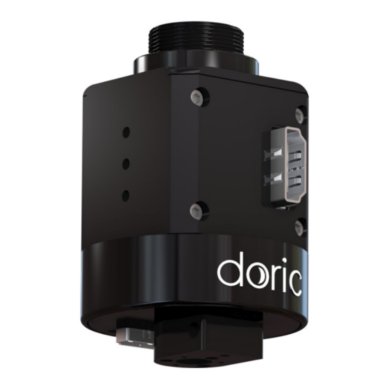
Figure 1.1: Electrical Rotary Joint The Doric Electric Rotary Joint is used to transmit electrical signal from a moving sample to a fixed recording system. It consists of high precision ball bearings and of a slip ring to transmit signal. It is composed of a Stator, which stays immo- bile, and a Rotor that moves (Fig. -
Page 4: Electrical Rotary Joint Holders
If the rotary joint is used only for electric signal, the Holder FRJ large alone (Fig.1.1). The gimbal mount GH FRJ (Fig.1.1) can also be used with the rotary joint alone, while allowing moderate rotation along 2 axes. Table 1.1: Electrical Rotary Joint Holders Holder ERJ... -
Page 5: Rotary Joint Harwin 12/Omnetics Pzn12 Adapter Kit
1.3 Rotary Joint Harwin 12/Omnetics PZN12 Adapter Kit To integrate the rotary joint within electrophysiology systems that use Omnetics PZN-12 connectors, an adapter kit can be provided. These elements allow a Harwin-connectorized rotary joint to serve as a rotary joint for Omnetics con- nectorized systems. -
Page 6: Operations Guide
Operations Guide 2.1 Rotary Joint Holders 2.1.1 Holder ERJ Figure 2.1: Installation of the rotary joints in the Holder ERJ... - Page 7 The holder can be installed in an experimental setup using 1/4 (or M6) screws and nuts. 2. Install the Electrical Rotary Joint in the Holder ERJ base (Fig. 2.1b) and secure it in place using the 3/4-32 UN secur- ing bolt (Fig. 2.1c).
- Page 8 2.1.2 Holder FRJ large The rotary joint is to be screwed into the Holder FRJ large (Fig. 2.3). Ensure the stability of the rotary joint in the thread to avoid slippage during use. The holder can be installed in a experimental setup using 1/4 (or M6) screws. Figure 2.3: Installation of the ERJ in the Holder FRJ large 2.1.3 GH FRJ The Gimbal Holder allows swivel movement of the rotary joint along 2 axes.
-
Page 9: Electrical & Optical Cables
(a) Electrical Connectors (b) Cable Placement (c) Electrical Rotary Joint Underside Figure 2.5: Electrical Connector Placement 1. Ensure that the electrical connectors are free of dust using an air duster before installing the cables. When not in use, install plastic caps on connectors for protection and cleanliness. - Page 10 1. Slide the cable holder rod with the cable clamp facing down into the pre-installed adapter situated under the rotary joint (Fig. 2.6). The rod is held in place using a 2-56 set-screw on the underside of the adapter. 2. Secure the clamp (facing down) onto the cable adapter rod using a #4-40 nylon set-screw (Fig. 2.6). Figure 2.6: Horizontal Cable Holder Standoff Placement 2.2.3 Optical Fibers The ERJ can be used alongside an optical rotary joint.
- Page 11 Figure 2.7: Electrical and Fiber-optic Rotary Joints - Cable Installation Chapter 2. Operations Guide...
-
Page 12: Specifications
Specifications Table 3.1: Harwin Electrical Connector Configuration Male (on rotary joint) Female (on adapter) Table 3.2: HDMI Electrical Connector Configuration Male (on cable) Female (on rotary joint) Table 3.3: HDMI Electrical Connector Pinouts HDMI Microscope HDMI Blackrock 2... - Page 13 Table 3.4: General Specifications SPECIFICATIONS VALUE NOTES HDMI connector pinout type Microscope, Blackrock 2 Female connector Harwin connector type Datamate L-Tek serie Male connector, 2 mm pitch, 12 contacts, 2 rows Number of contacts 6 or 12 Contact material Gold Maximum current 2 A per contact Contact resistance...
-
Page 14: Support
4.2 Warranty This product is under warranty for a period of 12 months. Contact Doric Lenses for return instructions. This warranty will not be applicable if the unit is damaged or needs to be repaired as a result of improper use or operation outside the conditions stated in this manual.
Need help?
Do you have a question about the Electrical Rotary Joint and is the answer not in the manual?
Questions and answers