
Summary of Contents for Puloon SiriUs-I
- Page 1 SiriUs-I User Manual Operating Manual HW Maintenance Manual © 1997-2020 PULOON Technology, Inc. All Rights Reserved. 1 / 141...
- Page 2 Operating Manual Table of Contents 1. Introduction ................................6 1.1 Menu Composition & User Authorization ......................7 2. Detail Menu by Functions ............................8 2.1 ATM Initial Setting Menu ............................13 2.1.1 Terminal ID ...............................13 2.1.2 Routing ID ................................13 2.1.3 ATM Serial No ..............................14 2.1.4 Denomination ..............................14 2.1.4.1 Denomination List............................15 2.1.4.2 Cassette Setting ............................16...
- Page 3 2.3.5.1 Count Image ..............................32 2.3.5.2 Display Time ..............................33 2.3.5.3 Image Upload ...............................33 2.3.6 EMV ..................................34 2.3.6.1 Fallback Option .............................34 2.3.6.2 Common AID Selection ..........................35 2.3.6.3 Magnetic Stripe Permit ..........................35 2.3.6.4 BIN Option ..............................36 2.3.6.4.1 Enable/Disable checking Default BIN......................36 2.3.6.4.2 Editing Default BIN List ..........................37 2.3.6.4.3 Uploading Default BIN List File ........................37 2.3.6.4.4 Enable/Disable checking Extra BIN List .....................38 2.3.6.4.5 Searching Extra BIN ...........................38...
- Page 4 2.3.23.2 Connecting Test ............................55 2.3.23.3 Manage Account ............................56 2.3.23.4 Set Interval ..............................57 2.3.23.5 Emergency Reset ............................57 2.4 Communication Setting Menu ...........................58 2.4.1 Modem Set ...............................58 2.4.1.1 Sound ................................58 2.4.1.2 Baudrate ................................59 2.4.1.3 Status ................................59 2.4.1.4 Predialing ..............................60 2.4.1.5 Timeout .................................60 2.4.1.5.1 View Timeout ............................61 2.4.1.5.2 Dial Timeout ..............................61 2.4.1.5.3 ENQ Timeout .............................62...
- Page 5 2.6.1.2 Search by Date ..............................80 2.6.1.3 Save Specific Month Data ..........................81 2.6.1.4 Search by Sequence Number ........................83 2.6.2 Error View ................................84 2.6.3 Error Detail ...............................84 2.6.3.1 View All .................................85 2.6.3.2 Search ................................86 2.7 System Mode Menu ............................88 2.7.1 Version ................................88 2.7.2 Setup Print ................................88 2.7.3 EJ Delete ................................89 2.7.4 Printer Test ...............................89...
- Page 6 1. Introduction [Maintenance mode] can be entered from transaction or error standby by using keypad, pressing ‘Clear’, ‘Enter’, ‘1’, ‘2’, ‘3’. ▶ Inserting Password to enter Maintenance Mode Screen Contents Insert default password ‘333333’ to enter. 6 / 141...
- Page 7 1.1 Menu Composition & User Authorization Some settings of [Maintenance mode] function may be limited by user authority. Menu composition and user authorization are as follows by chart 1.1. Chart 1.1 Maintenance mode Menu Composition and User Authorization (M: Master Mode, S: System Mode, T: Teller Mode) Maintenance Mode Authorization Main...
- Page 8 2. Detail Menu by Functions ◎ [CORD ONLY] The 5 minutes timer will be activated when the switching company is “DNS” and the lower vault door is closed. ◎ [ALL] The 5 minutes timer will be activated when the “Screen Timer” option is enabled and the lower vault door is closed.
- Page 9 ▶ System Setup ◎ Sub name is shown at the right-top corner. ▶ Host Setup ◎ Sub name is shown at the right-top corner. ◎ If the network setting is Modem, ‘Phone No’ button will be shown. 9 / 141...
- Page 10 ▶ Cash Menu ◎ Sub name is shown at the right-top corner. ▶ Transaction Setup ◎ Sub name is shown at the right-top corner. ◎ If the network setting is TCP/IP, the “TCPIP Set’ button will be shown. If not, ‘Modem Set’ button will be shown. ▶...
- Page 11 ▶ TCPIP Set Menu 11 / 141...
- Page 12 ▶ Modem Set Menu 12 / 141...
- Page 13 2.1 ATM Initial Setting Menu 2.1.1 Terminal ID ◎ Location : Host Setup Terminal ID Screen Contents Setting the assigned Terminal ID 1. Use ‘Clear’, ‘Character’ and ‘Number’ buttons to enter the ID. 2. Press ‘OK’ button to save and exit.
- Page 14 2.1.3 ATM Serial No ◎ Location : Transaction Setup ATM Serial No. Screen Contents Setting the assigned ATM Serial Number. 1. Use ‘Clear’, ‘Character’ and ‘Number’ buttons to enter the number. 2. Press ‘OK’ button to save and exit. 3.
- Page 15 Screen Contents Press ‘Denom List’ button to change denomination lists. Press ‘Cassette’ button to change the denomination of each cassette. 2.1.4.1 Denomination List ◎ Location : Cash Menu Denomination Denom List Screen Contents 1. Choose the menu corresponds to number of denomination by ‘Next’...
- Page 16 2.1.4.2 Cassette Setting ◎ Location : Cash Menu Denomination Cassette Screen Contents 1. Choose the cassette to change the denomination. 2. Set the denom value. 3. Press ‘OK’ button to save and exit. 4. Press ‘Exit’ button to exit without saving 2.1.5 Receipt Printer Type ◎...
- Page 17 2.1.6 Card Reader Type ◎ Location : Transaction Setup Setup ATM Card Reader Type Screen Contents Setting the card reader type 1. Choose the card reader type supported by the ATM. ‘1’ is default. 2. Press ‘OK’ button to save and exit.
- Page 18 2.1.8 Switching (Processor) Company ◎ Location : Transaction Setup Setup ATM Switching Company Screen Contents Setting the switching company 1. Choose the processor from the list for transaction. 2. Press ‘OK’ button to save and exit. 3. Press ‘Exit’ button to exit without saving 2.1.9 Nation ◎...
- Page 19 2.1.10 Language ◎ Location : Transaction Setup Language Screen Contents Setting the language 1. Select language(s) to use. 2. Press ‘OK’ button to save and exit. 3. Press ‘Exit’ button to exit without saving * Currently, English is default and Spanish is option.
- Page 20 If a hardware ADA board is supplied, ‘H/W ADA Permit’ button will be shown. SIriUs-I : H/W & S/W ADA SiriUs-II : S/W ADA only 2.1.12.1 ADA Permit ◎ Location : Transaction Setup Setup ATM Next ADA S/W ADA Permit...
- Page 21 Screen Contents Setting the usage of HW 1. Enable/Disable ADA status. 2. Press ‘OK’ button to save and exit. 3. Press ‘Exit’ button to exit without saving 2.1.13 Data/Time ◎ Location : Host Setup Date/Time Screen Contents Choose sub menu 21 / 141...
- Page 22 2.1.13.1 Data/Time Set ◎ Location : Host Setup Date/Time Date/Time Set Screen Contents Setting date and time 1. Set system Date and Time. 2. Press ‘OK’ button to save and exit. 3. Press ‘Exit’ button to exit without saving 3.
- Page 23 2.1.14 Change Password 2.1.14.1 Change Host Password ◎ Location : Host Setup Password Screen Contents Changing the host password 1. Insert old password and press ‘ENTER’ key or ‘OK’ button. 2. Insert new password and press ‘ENTER’ key or ‘OK’ button.
- Page 24 2.1.14.3 Customer Password ◎ Location : Customer Setup Password Screen Contents Changing the customer password 1. Insert old password and press ‘ENTER’ key or ‘OK’ button. 2. Insert new password and press ‘ENTER’ key or ‘OK’ button. 3. Insert new password again and press ‘ENTER’...
- Page 25 Screen Contents 2. If the password is default, a warning message will be shown. 3. Select password type. 25 / 141...
- Page 26 Screen Contents 4. Insert old password and press ‘ENTER’ key or ‘OK’ button. 5. Insert new password and press ‘ENTER’ key or ‘OK’ button. 6. Insert new password again and press ‘ENTER’ key or ‘OK’ button. 7. Press ‘Exit’ button to exit without saving 26 / 141...
- Page 27 2.2 Cash Register / Settlement Setting Menu 2.2.1 Add Cash ◎ Location : Customer Setup Add Cash Screen Contents Add cash or clear cassette 1. Choose the box and denomination 2. Enter the amount and press ‘Apply’ button. The inserted amount will be sent to the host and a receipt will be printed.
- Page 28 Screen Contents 2.2.2 Settlement ◎ Location : Customer Setup Settlement Screen Contents [Trial Close] Total amounts are sent to the Host and a receipt will be printed. The registered amounts are not deleted. [Day Close] Total amounts are sent to the Host and a receipt will be printed.
- Page 29 Screen Contents [Trial CST] A receipt will be printed. The registered amounts are not deleted. [Clear CST] A receipt will be printed. The registered amounts will be deleted. 29 / 141...
- Page 30 2.3 Transaction Setting Menu 2.3.1 Select Receipt ◎ Location : Transaction Setup Setup ATM Next (2 times) Select Receipt Screen Contents Setting the usage of receipt selecting option 1. Enable to print receipt by selection and Disable to print automatically.
- Page 31 2.3.3 Check Balance ◎ Location : Transaction Setup Setup ATM Next (2 times) Check Balance Screen Contents Setting the usage of balance checking 1. Enable or disable checking default balance before withdraw and transfer transaction. 2. Press ‘OK’ button to save and exit.
- Page 32 2.3.5 Idle Display ◎ Location : Transaction Setup Setup ATM Next (3 times) Idle Display Screen Contents Setting for display items on the transaction standby screen. 2.3.5.1 Count Image ◎ Location : Transaction Setup Setup ATM Next (3 times) Idle Display ...
- Page 33 2.3.5.2 Display Time ◎ Location : Transaction Setup Setup ATM Next (3 times) Idle Display Display Time Screen Contents Setting the time to display 1. Setting for time display time length for each image. 2. Press ‘OK’ button to save and exit.
- Page 34 2.3.6 EMV ◎ Location : Customer Setup Next EMV Screen Contents EMV transaction Setting 2.3.6.1 Fallback Option ◎ Location : Customer Setup Next EMV Fallback Option Screen Contents Setting the usage of fallback option 1. Enable or disable to accept MS Transaction.
- Page 35 2.3.6.2 Common AID Selection ◎ Location : Customer Setup Next EMV Common AID Selection Screen Contents Setting the usage of common AID selection 1. Enable or disable to select the common AID automatically 2. Press ‘OK’ button to save and exit.
- Page 36 2.3.6.4 BIN Option ◎ Location : Customer Setup Next EMV BIN Option Screen Contents Choose sub menu. 2.3.6.4.1 Enable/Disable checking Default BIN ◎ Location : Customer Setup Next EMV BIN Option Default BIN List Enable/Disable Screen Contents Setting the usage of default...
- Page 37 2.3.6.4.2 Editing Default BIN List ◎ Location : Customer Setup Next EMV BIN Option Editing Default BIN List Screen Contents Add or Delete AID bin 1. To add new one, insert AID BIN code (4 digit) and press ‘Add’...
- Page 38 2.3.6.4.4 Enable/Disable checking Extra BIN List ◎ Location : Customer Setup Next EMV BIN Option Extra BIN List Enable/Disable Screen Contents Setting the usage of Extra 1. Enable or disable to check the extra BIN. 2. Press ‘OK’ button to save and exit.
- Page 39 2.3.6.4.6 Uploading Extra BIN List File ◎ Location : Customer Setup Next EMV BIN Option Extra BIN List File Upload Screen Contents Extra BIN list file will be copied from SD card or USB memory to the internal storage.
- Page 40 2.3.7.1 Cash Range Set ◎ Location : Customer Setup Next Amount Range Cash Range Set Screen Contents Setting the cash range 1. Set the checked amount range. 2. Press ‘OK’ button to save and exit. 3. Press ‘Exit’ button to exit without saving.
- Page 41 2.3.8 Surcharge ◎ Location : Customer Setup Next (2 times) Surcharge Mode Screen Contents Setting for Surcharge 2.3.8.1 Surcharge Set ◎ Location : Customer Setup Next (2 times) Surcharge Mode Surcharge Set Screen Contents Setting the usage of surcharge 1.
- Page 42 2.3.8.2 Surcharge Owner ◎ Location : Customer Setup Next (2 times) Surcharge Mode Owner Screen Contents Setting the surcharge owner 1. Set the owner of surcharge. 2. Press ‘OK’ button to save and exit. 3. Press ‘Exit’ button to exit without saving.
- Page 43 2.3.8.4 Surcharge Percent ◎ Location : Customer Setup Next (2 times) Surcharge Mode Percent Screen Contents Setting the surcharge percent 1. Set surcharge percent (00.00 ~ 99.99%) 2. Press ‘OK’ button to save and exit. 3. Press ‘Exit’ button to exit without saving.
- Page 44 2.3.8.6 BIN List ◎ Location : Customer Setup Next (2 times) Surcharge Mode No Surcharge Bin List Screen Contents Choose sub menu. 2.3.8.6.1 BIN List Enable/Disable ◎ Location : Customer Setup Next (2 times) Surcharge Mode No Surcharge Bin List ...
- Page 45 2.3.8.6.2 BIN List Set ◎ Location : Customer Setup Next (2 times) Surcharge Mode No Surcharge Bin List Bin List Set Screen Contents Add or Delete bin list 1. To add new one, insert bin code (6 digit) and press ‘Add’...
- Page 46 2.3.9 Coupon ◎ Location : Customer Setup Coupon Screen Contents Menu for coupon function setting 2.3.9.1 Coupon Message ◎ Location : Customer Setup Coupon Message Screen Contents Setting coupon messages 1. Insert messages to print on receipt 2.
- Page 47 2.3.9.2 Coupon Frequency ◎ Location : Customer Setup Coupon Frequency Screen Contents Setting the coupon frequency 1. Enable or disable Setting number of messages to print. 2. Press ‘OK’ button to save and exit. 3. Press ‘Exit’ button to exit without saving.
- Page 48 2.3.11 Fast Cash ◎ Location : Cash Menu Fast Cash Screen Contents During withdrawal transaction, setting for the Fast Cash amount for buttons 1. Select desired button to change and insert the amount. 2. Press ‘OK’ button to save and exit.
- Page 49 2.3.13 Background Image Upload ◎ Location : Transaction Setup Setup ATM Background Upload Screen Contents Applying the desired background image 49 / 141...
- Page 50 2.3.14 SW Download ◎ Location : Transaction Setup Setup ATM Next SW Download Screen Contents Applying new AP software 2.3.15 Reboot Time ◎ Location : Transaction Setup Setup ATM Next Reboot Time Screen Contents Setting the rebooting time 1.
- Page 51 2.3.16 Change Text Color ◎ Location : Transaction Setup Setup ATM Next (2 times) Change Text Color Screen Contents Changing the text color 1. Select desired text color. 2. Press ‘OK’ button to save and exit. 3. Press ‘Exit’ button to exit without saving.
- Page 52 2.3.18 Bill.Dat Copy ◎ Location : Transaction Setup Setup ATM Next (3 times) Bill.Dat Copy To SD Card Screen Contents Copying withdrawal data file to SD Card 1. Insert SD Card to the slot and then press ‘Bill.Dat Copy to SD Card’.
- Page 53 2.3.20 Use 12-Digit ◎ Location : Transaction Setup Setup ATM Next (4 times) Use 12-Digit Screen Contents 1. Enable or disable to use. 2. Press ‘OK’ button to save and exit. 3. Press ‘Exit’ button to exit without saving.
- Page 54 2.3.22 Set Screen Timer ◎ Location : Transaction Setup Setup ATM Next (5 times) Screen Timer Screen Contents Setting Screen Timer in case of returning to the Idle screen after 5 minutes 1. Enable or disable to use. 2.
- Page 55 2.3.23.1 RMS Server ◎ Location : Host Setup Monitoring RMS Server Screen Contents Setting RMS Server Information 1. Insert RMS Server IP and port number. 2. Press ‘OK’ button to save and exit. 3. Press ‘Exit’ button to exit without saving.
- Page 56 2.3.23.3 Manage Account ◎ Location : Host Setup Monitoring Manage Account Screen Contents Managing Account (TID folder) of RMS Server 1. Create or Delete Account (TID folder) of RMS Server. 2. Press ‘OK’ button to save and exit. 3.
- Page 57 2.3.23.4 Set Interval ◎ Location : Host Setup Monitoring Set Interval Screen Contents Setting RMS interval time 1. Insert RMS interval time. 2. Press ‘OK’ button to save and exit. 3. Press ‘Exit’ button to exit without saving. * If the account (TID folder) is not created, the interval cannot be set.
- Page 58 2.4 Communication Setting Menu Modem Set 2.4.1 ◎ Location : Transaction Setup Modem Set ◎ This menu will be shown in case of MODEM only. Screen Contents Setting menu for Modem transfer Sound 2.4.1.1 ◎ Location : Transaction Setup Modem Set Sound Screen Contents Modem sound setting...
- Page 59 Baudrate 2.4.1.2 ◎ Location : Transaction Setup Modem Set Baudrate Screen Contents Transfer rate setting Status 2.4.1.3 ◎ Location : Transaction Setup Modem Set Status Screen Contents Status check 59 / 141...
- Page 60 Predialing 2.4.1.4 ◎ Location : Transaction Setup Modem Set Predialing Screen Contents Setting for use of Pre-dialing during transaction Timeout 2.4.1.5 ◎ Location : Transaction Setup Modem Set Timeout Screen Contents Setting the timeout value between ATM and the Host. 60 / 141...
- Page 61 Timeout 2.4.1.5.1 View Screen Contents Reviewing the timeout values. Timeout 2.4.1.5.2 Dial Screen Contents Setting the timeout of dialing. 1. Enter desired timeout value. 2. Press ‘OK’ button to save and exit. 3. Press ‘Exit’ button to exit without saving. 61 / 141...
- Page 62 Timeout 2.4.1.5.3 ENQ Screen Contents Setting the timeout of ENQ. 1. Enter desired timeout value. 2. Press ‘OK’ button to save and exit. 3. Press ‘Exit’ button to exit without saving. Timeout 2.4.1.5.4 ACK Screen Contents Setting the timeout of ACK.
- Page 63 Timeout 2.4.1.5.5 STX Screen Contents Setting the timeout of STX. 1. Enter desired timeout value. 2. Press ‘OK’ button to save and exit. 3. Press ‘Exit’ button to exit without saving. Timeout 2.4.1.5.6 ETX Screen Contents Setting the timeout of ETX.
- Page 64 Timeout 2.4.1.5.7 EOT Screen Contents Setting the timeout of EOT. 1. Enter desired timeout value. 2. Press ‘OK’ button to save and exit. 3. Press ‘Exit’ button to exit without saving. Phone No. 2.4.2 ◎ Location : Host Setup Phone No. ◎...
- Page 65 2.4.3 Redundancy Server ◎ Location : Transaction Setup Setup ATM Next (2 times) Redundancy Server ◎ This menu will be shown in case of TCP/IP only. Screen Contents Setting the usage of redundancy server 2.4.4 TCPIP Set ◎...
- Page 66 Screen Contents Setting menu for TCPIP communication in case of URL option is not selected 2.4.4.1 Server URL or IP ◎ Location : Transaction Setup TCPIP Set Server URL(or IP ◎ This menu will be shown in case of TCP/IP only. Screen Contents If the Redundancy server...
- Page 67 Screen Contents If URL function is Enabled, then Host server URL address and communication Port must be set. 1. Insert the server URL and port number. 2. Press ‘OK’ button to save and exit. 3. Press ‘Exit’ button to exit without saving.
- Page 68 2.4.4.2 ATM IP ◎ Location : Transaction Setup TCPIP Set ATM IP Screen Contents Setting of ATM IP address communication Port 1. Insert the ATM IP, subnet mask, gateway and DNS. 2. Press ‘OK’ button to save and exit. 3.
- Page 69 2.4.4.3.1 TCP Length Screen Contents 1. Inclusive or Exclusive to use. 2. Press ‘OK’ button to save and exit. 3. Press ‘Exit’ button to exit without saving. 2.4.4.3.2 TCP Type Screen Contents 1. Server or Client to use. 2. Press ‘OK’ button to save and exit.
- Page 70 2.4.4.4 TCP/IP Timeout ◎ Location : Transaction Setup TCPIP Set Timeout Screen Contents Choose menu to change. 2.4.4.4.1 View Timeout Screen Contents Reviewing the timeout values. 70 / 141...
- Page 71 2.4.4.4.2 Session Timeout Screen Contents Setting the timeout of making session between ATM and the Host. 1. Enter desired timeout value. 2. Press ‘OK’ button to save and exit. 3. Press ‘Exit’ button to exit without saving. 2.4.4.4.3 Send Timeout Screen Contents Setting the timeout of...
- Page 72 2.4.4.4.4 Receive Timeout Screen Contents Setting the timeout of receiving message from the Host. 1. Enter desired timeout value. 2. Press ‘OK’ button to save and exit. 3. Press ‘Exit’ button to exit without saving. 2.4.4.4.5 ETX Timeout Screen Contents Setting the timeout of receiving ETX (End Of Text) field.
- Page 73 2.4.4.5 DHCP ◎ Location : Transaction Setup TCPIP Set DHCP Screen Contents Setting the usage of DHCP option 1. Enable or disable the DHCP option.. 2. Press ‘OK’ button to save and exit. 3. Press ‘Exit’ button to exit without saving.
- Page 74 2.4.4.7 URL Option ◎ Location : Transaction Setup TCPIP Set URL Option Screen Contents Setting the URL option 1. Enable or disable the URL option.. 2. Press ‘OK’ button to save and exit. 3. Press ‘Exit’ button to exit without saving.
- Page 75 2.4.6 ENQ Check ◎ Location : Transaction Setup Setup ATM Next (3 times) ENQ Check Screen Contents If enabled, the AP will check the ENQ (ENQuiry) field of received message. 2.4.7 EOT Check ◎ Location : Transaction Setup Setup ATM Next (3 times) EOT Check Screen Contents If enabled, the AP will check...
- Page 76 2.5 Master Key Setting Menu 2.5.1 Master A ◎ Location : Host Setup Key Management Insert Master A ◎ Before doing this, you’d better changing EPP password #1 and #2. ◎ To entering this menu, you must enter EPP password #1 and #2. Screen Contents Select Master Key Type...
- Page 77 2.5.2 Master B ◎ Location : Host Setup Key Management Insert Master B ◎ Before doing this, you’d better to change EPP password #1 and #2. ◎ To entering this menu, you must enter EPP password #1 and #2. Screen Contents Insert the Part B master Key.
- Page 78 2.6 Electronic Journal Operation and Error List Menu 2.6.1 E-Journal ◎ Location : Customer Setup E-Journal Screen Contents Choose sub menu. 2.6.1.1 View All ◎ Location : Customer Setup E-Journal View All Screen Contents In this menu, you can view, check, print and save electronic journal contents to SD card or USB memory.
- Page 79 Screen Contents [Save] If SD card or USB memory exists, electronic journal data will be copied. [Print] - Current : Print currently displayed - All data : Print all data 79 / 141...
- Page 80 Screen Contents [Print – Current]/All data - Detail : Print detailed contents. - Simple : Print simply 2.6.1.2 Search by Date ◎ Location : Customer Setup E-Journal Search by Date Screen Contents Electronic journal contents can be viewed by specific date.
- Page 81 Screen Contents 2.6.1.3 Save Specific Month Data ◎ Location : Customer Setup E-Journal Search Screen Contents Save specific month’s data to a SD card. - WAIT : Searching data - FAILED : No SD card inserted or copy failed - DONE : copy success 81 / 141...
- Page 82 Screen Contents 82 / 141...
- Page 83 2.6.1.4 Search by Sequence Number ◎ Location : Customer Setup E-Journal Search by Sequence No. Screen Contents Electronic journal contents can be viewed by specific sequence number. 83 / 141...
- Page 84 2.6.2 Error View ◎ Location : System Setup Error View Screen Contents Menu that shows error codes by different module type and contents 2.6.3 Error Detail ◎ Location : System Setup Error Detail Screen Contents Choose sub menu. 84 / 141...
- Page 85 2.6.3.1 View All ◎ Location : System Setup Error Detail View all Screen Contents Menu that shows past errors by time periods [Print] 85 / 141...
- Page 86 Screen Contents [Save] If SD card or USB memory exists, error journal data will be copied. 2.6.3.2 Search ◎ Location : System Setup Error Detail Search Screen Contents Error contents can be viewed by specific date. 86 / 141...
- Page 87 Screen Contents 87 / 141...
- Page 88 2.7 System Mode Menu 2.7.1 Version ◎ Location : System Setup Version Screen Contents Menu that shows the S/W and device versions 2.7.2 Setup Print ◎ Location : System Setup Setup Print Screen Contents Menu that can print ATM setting information.
- Page 89 2.7.3 EJ Delete ◎ Location : System Setup EJ Delete Screen Contents Menu that can delete all stored contents of electronic journal. If ‘Yes’ button is pressed, all E-Journal data will be deleted. 2.7.4 Printer Test ◎ Location : System Setup Diagnostics Print Test Screen Contents Menu that can test the...
- Page 90 2.7.5 CDM Test ◎ Location : System Setup Diagnostics CDM Test Screen Contents Menu that can test the Cash Dispensing Module. CST2 and CST3 button will be shown by the count of cassette or CDM type. 1. Select desired cassette. 2.
- Page 91 2.7.7 Key Test ◎ Location : System Setup Diagnostics Key Test Screen Contents Menu that can test function keys and pinpad. 1. Press any function key and number on pinpad. 2. Any character or number will be displayed in the ‘Pressed key’...
- Page 92 2.7.9 TCP/IP Test ◎ Location : System Setup Diagnostics TCP/IP Test Screen Contents Menu that can test the LAN Device. 1. Press ‘Test’ button. 2. Any message will be displayed in the Result field. 3. Press ‘Exit’ to stop. 2.7.10 IC C/R Test ◎...
- Page 93 2.8 ETC 2.8.1 Initialize / Reset ◎ Location : Device Reset Screen Contents 2.8.2 Select CDM Type ◎ If the OS is changed or updated by using SD Card, the CDM type must be selected. Screen Contents 93 / 141...
-
Page 94: Table Of Contents
HW Maintenance Manual Table of Contents 1 External Features ............................95 Internal Features .......................... 96 2 System Specifications ..........................97 3 H/W Operation and Maintenance ....................... 98 SYSTEM POWER .......................... 98 System Block Diagram ........................99 Embedded-PC (WinCE 6.0) ......................100 3.3.1 Device Parts ........................100 3.3.2... -
Page 95: External Features
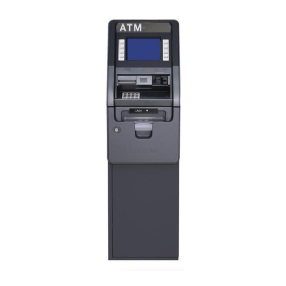
1 External Features Figure 1. Layout of PL-MU101T (Front View) 95 / 141... -
Page 96: Internal Features
Internal Features Figure 2. Layout of PL-MU101T (Door Open) 96 / 141... -
Page 97: System Specifications
2 System Specifications FEATURE Specifications Operating system : Windows CE 6.0 SYSTEM PLATFORM Embedded, ARM11 533/667Hz Electronic journal : 10,000 transaction SCREEN SIZE 8" FUNCTION KEYS Metal Key UL291 CERTIFICATION Business Hours PRINTER 80mm Standard PCI Compliant KEYPAD ADA Compliant Dip Style CARD READER EMV Level 1. -
Page 98: W Operation And Maintenance
3 H/W Operation and Maintenance SYSTEM POWER 1) Turn on the Power Switch. Figure 3. Power Switch of SMPS >> Turn on Power Switch of SMPS. >> To turn off the system power, and turn off the power switch of SMPS. 98 / 141... -
Page 99: System Block Diagram
System Block Diagram Figure 4. Block Diagram 99 / 141... -
Page 100: Embedded-Pc (Wince 6.0)
Embedded-PC (WinCE 6.0) Device Parts 3.3.1 Figure 5. Device Port COM2 : KEPAD(EPP) COM3 : Thermal Printer(DH) COM5 : Cash Dispenser(CDM) COM6 : Card Reader(C/R) COM7 : Reserved COM1 : Debug ETC Parts Port 3.3.2 Figure 6. ETC Parts Port >>... -
Page 101: How To Insert And Remove Sd Card
How to Insert and Remove SD Card 3.3.3 Insert >> You can insert the SD Card on the back of the Main Control Unit. You will find a slot in which you can plug the SD card (as shown on the pictures). How to Load &... -
Page 102: Check For Abnormality Of Electric Power
Check for Abnormality of Electric Power 3.3.5 LED18 : 12V Power ON LED1 : 5V Power ON LED19 : 3.3V Power ON ※ 12V, 5V External Power ● Voltage check : Check for the voltage with tester 1. EC15 check on both ends, 3.3V 2. -
Page 103: Check For Abnormality In Com Port
Check for Abnormality in COM Port 3.3.6 Check for Abnormality in COM Port using LOOPBACK JIG >> Run CH6410 COMTEST P/G >> Choose ALL START >> Port to be Test (예 :COM5) Execute - Normal : R , D color flicker (Red, Blue) - Faulty : No change in color 103 / 141... -
Page 104: Check Point When Screen Looks Abnormal
Check point when screen looks abnormal 3.3.7 1) Check for the damage to J2 LCD Inverter connecter 2) Check for connection on LCD cable Figure 7. LCD Controller Board 104 / 141... -
Page 105: Bill Dispenser : Lcdm
Bill Dispenser : LCDM To refill cassette with cash 3.4.1 1) Pull out the cassette using the handle marked handle below. 2) When inserting the cassette back after refill, simply push the cassette all the way back. Since there is a spring at the end pushing back, you must push all the way in until it feels snug, and feeling the click. -
Page 106: Fix Dispenser Error
Fix Dispenser Error 3.4.2 1) Check the back of the dispenser for power and data cable. 2) Pull the cassette forward, and check for anything that may be blocking the path. 3) Check for the path on the dispenser for anything in the path. In case of a Jam remove the object in the following way. -
Page 107: Card Reader
Card Reader Card reader instruction 3.5.1 1) When instructed to do so on the screen, insert the card all the way back to the card reader. As the Dip Type, push all the way until it clicks. In case of card reader error 3.5.2 1) Check the power switch and data cable connection. -
Page 108: Keypad(Pci3.0)
Keypad(PCI3.0) 1) When power is provided, normally Buzzer will sound. 2) Check the power and data cable connection. >> check the PC (Comport) and Cable connection. >> Keypad Cable consists of COM2 (RJ45 + Molex5264-02) Figure 13. Keypad Cable drawing 108 / 141... -
Page 109: Smps
SMPS 1) Check connection +5V (2Pin) : Embedded Board +12V (4Pin) : Card Reader, Embedded Board +24V (6Pin) : Cash Dispenser. Receipt Printer Input Voltage Range : AC90V~264V Output Voltage Range : DC 11.4V~12.6V, 23.5V~26.5V, 4.75V~5.25V Figure 14. SMPS Connector 109 / 141... -
Page 110: Receipt Printer
Receipt Printer Printer Module Name of each parts 3.8.1 Figure 15. Printer name for each parts 1 — Feed/Cut button 2 — Error LED 3 — Power LED 4 — Paper near sensor socket 5 — Paper guide block 6 — Communication interface (USB or serial interface is optional) 7 —... - Page 111 * Cut paper: the printer will cut paper if press the FEED / CUT button for two times continuously. * Caution The printer will not run when press the FEED button under error status. 2) Button for opening and closing the top cover * After pressing the button for opening and closing the top cover, the top cover module can be opened for maintenance work, such as clear jammed paper jam, clean the print head/platen rollers.
-
Page 112: Method Of Installation And Removal Of Paper
Method of installation and removal of Paper 3.8.3 * Caution Before installing the paper roll, make sure the specification of paper roll is in conformity with requirements of printer 1) Turn on the power, and then place the paper head in the paper feeding path as shown Figure 16. -
Page 113: Solution For Common Errors
* Caution Before loading paper, cut the paper head trim according to the figure below: Figure 17. Paper head Before loading paper, make the paper flat to ensure the paper be fed smoothly into the path. Figure 18. Radlan of paper head Solution for common errors 3.8.4 1) Problems during paper loading... - Page 114 Problems during printing Problem Possible Reasons Solutions The receipt can’t be ejected Paper jams. Check paper feeding path, remove out smoothly. wastepaper and reload paper. Printout is not clear. The paper is loaded in wrong Load the paper roll correctly. direction or its quality is poor.
- Page 115 4) Other problems Problem Possible Reasons Solutions LED does not light and The printer is not connected with Connect the printer with power printer the power correctly. correctly. does not work. The printer isn’t turned on. Turn on the printer. The printer does not Printer is in error status.
- Page 116 Open Security Door (Electronic Lock) Figure 19. Electronic Lock Factory Default Password The default electronic lock password is: To open : *123456# To close : *# : Open : Close 116 / 141...
- Page 117 Change the Password 1) Press * (then the red light will be on). 2) Press ‘red button’ (Located inside the cabinet, behind the lock). Figure 20. Inside the cabinet 3) Set new password number (e.g. 1234) then press # (then the blue or green light will be on).
-
Page 118: Installation Space
4 Installation space Figure 21. Installation space #1 (Plan view) 118 / 141... - Page 119 Figure 22. Installation space #2 (Side view) 119 / 141...
-
Page 120: Mu101T Dimension
5 PL-MU101T Dimension Figure 23. Dimension of PL-MU101T 120 / 141... -
Page 121: Appendix A. Device Error Code
Appendix A. Device Error Code A-1. CDM (LCDM-1K) CODE ERROR DESCRIPTION CORRECTIVE ACTION CS001 Rx Signal Error Check the connection of the device cable. If CS002 Rx Error the problem persists, please replace the CS003 Rx Error (ETC) device, cable or port. CS004 Port Open Error CS005... - Page 122 CS049 Diverter Solenoid or SOL Sensor Error CS04A SOL Sensor Error CS04E Purge Error (Jam at Div Sensor) A-2. CDM (LCDM-2K) CODE ERROR DESCRIPTION CORRECTIVE ACTION C2001 Rx Signal Error Check the connection of the device cable. If C2002 Rx Error the problem persists, please replace the C2003 Rx Error (ETC)
- Page 123 (between EJT Sensor and EXIT Sensor) C203F Reject Tray is not recognized C2040 Lower Bill End C2041 Motor Stop C2042 JAM at DIV Sensor C2043 Timeout (from DIV Sensor to EJT Sensor) C2044 Over Reject C2045 Upper CST is not recognized C2046 Lower CST is not recognized C2047...
- Page 124 C4044 Pickup Error (4 Cassette) C4002 Timeout on feeding between CHK Sensor and RVDT Start Sensor C4003 Timeout on feeding between DIV Sensor and EJT Sensor C4004 Timeout on feeding between EJT Sensor and EXIT Sensor C4005 A note is not passed on EXIT Sensor C4006 Ejecting the note suspected as rejected C4007...
- Page 125 command C4032 Not to give Verify command on Reset after downloading program C4033 Failure of writing on program area C4034 Failure of Verify C4112 detecting SENS0_DIV1 C4113 detecting SENS0_DIV2 C4114 detecting SENS0_EJT C4115 detecting SENS0_EXT C4116 detecting SENS0_RJT C4117 detecting SENS0_SOL C4118 detecting SENS1_RVSTL C4119...
- Page 126 C5A06 Ejecting the note suspected as rejected C5A07 Abnormal note management Reset the machine. If problems persist, please C5A08 Abnormal note management contact the service provider. (Please refer to C5A09 Jamming on EJT Sensor CDM maintenance manual) C5A0A Jamming on EXT Sensor C5A0B Detecting notes on the path before start of pick-up...
- Page 127 C5A31 Check1_Right Sensor is Always On C5A32 Cassette1 Sensor is Always On C5A33 Check2_Left Sensor is Always On C5A34 Check2_Right Sensor is Always On C5A35 Cassette2 Sensor is Always On. Reset the machine. If problems persist, please C5A36 Check3_Left Sensor is Always On contact the service provider.
- Page 128 (In Case of Near End Detection Mode) C5A5D Cash-Cassette2 is Near-End (In Case of Near End Detection Mode) C5A5E Cash-Cassette3 is Near-End (In Case of Near End Detection Mode) C5A5F Cash-Cassette4 is Near-End (In Case of Near End Detection Mode) C5A60 Pick-up Error in Cassette1 ( Banknotes exist in Cash Cassette1)
- Page 129 A-5. Pinpad (KeyU) CODE ERROR DESCRIPTION CORRECTIVE ACTION ES001 Rx (FIFO) Signal Error ES002 Rx (OVERRUN) Error ES003 Rx Error (ETC) ES004 Port Open Error The connection between the MCU and the communication port is not established. Please check the connection between MCU and the PC.
- Page 130 ES418 Command Executes Failure ES419 BCC Check Error ES420 Data Receive Timeout ES421 Invalid Master Key ES422 The Key is too simple, each byte is same Invalid command tamper reach to 5 times, EPP has been locked ES423 Key invalid or same values Key has been stored in device ES424 Key Invalid or does not be activated...
- Page 131 MCU board EZ505 SP Application Error Software error. Please contact the EZ506 Idle Processing Error manufacturer if these error happen. EZ507 Retry Open Command EZ508 Working Key Length Error (only 32bytes) EZ509 MKey1 Length Error (only 32bytes) EZ510 MKey2 Length Error (only 32bytes) EZ511 MAC Master Key Length Error EZ512...
- Page 132 EZ61D Length of Card Number is wrong EZ620 Memory runs off EZ624 Locked Keypad EZ625 Padding Data Length is wrong EZ626 Didn't set successfully in given time EZ629 Password is not checked EZ630 Card Number or Padding Data is incorrect in PINBLOCK EZ634 Need Removal Authentication...
- Page 133 GS004 GPIO Port Number Error GS012 GPIO Port Number Error GS005 Unknown Value Returned GS006 GPIO Default Error GS013 GPIO Default Error GS007 Invalid Data (Status) GS008 Invalid Data (Status) KS001 Rx (FIFO) Signal Error Check the connection of the device cable. If WS001 Rx (FIFO) Signal Error problem persists, replace the device, cable or...
- Page 134 A-8. CARD (Sankyo) CODE ERROR DESCRIPTION CORRECTIVE ACTION IS001 Rx(FIFO) Signal Error Check the connection of the device cable. If IS002 Rx(OVERRUN) Error problem persists, replace the device, cable, or IS003 Rx Error (ETC) port. IS004 Port Open Error IS005 SP Application Error Software error.
- Page 135 IS320 Card Read Response Error IS321 Card Read Response Error IS322 Card Read Response Error IS323 Card End Response Error IS888 Undefined Code Received A-9. Printer (Rexod) CODE ERROR DESCRIPTION CORRECTIVE ACTION PS001 RX FIFO Error Check the connection of the Printer cable. If PS002 RX Over Run problem persists, replace the Printer, cable or...
- Page 136 problem persists, replace the Printer, cable or the port. PA017 Paper End Supply Paper PA018 Head Overheat Error Hardware error. Reset the machine. If PA019 Print Buffer Full problems persist, please contact the PA020 Paper Load Error manufacturer. PA021 Printing Jam PA022 System H/W Error A-11.
- Page 137 TS014 Receive Data Default Error Please Reset the machine or check the TS020 Send Data Default Error Wireless Modem or LAN cable, port TS0N0 TCP/IP Connection Failure connection and TCPIP communication TS0S0 TLS Lib Initialize Error connection. If problems persist, please contact TS0S1 VISA2(TLS) VISA2 Type Setting Error the service provider.
- Page 138 TS3N6 VISA2(TCP/IP) Recv ACK Error TS3N8 VISA2(TCP/IP) Recv ENQ Error TS3E2 VISA2(TCP/IP) WANT_WRITE Error (ACK): TS3E3 VISA2(TCP/IP) CONN_RESET Error (ACK) TS3E4 VISA2(TCP/IP) SEND_FAILED Error (ACK) TS3E5 VISA2(TCP/IP) UNKNOWN_HOST Error (ACK) TS3E6 VISA2(TCP/IP) SOCKET_FAILED Error (ACK) TS3E7 VISA2(TCP/IP) CONNECT_FAILED Error (ACK) TS3E8 VISA2(TCP/IP) BIND_FAILED Error (ACK) TS3E9...
- Page 139 TS5EE VISA2(TCP/IP) Out of Case Error (DataSend) A-13. Modem CODE ERROR DESCRIPTION CORRECTIVE ACTION MS001 Port Error Check the connection of the Modem cable. If MS002 Port Close Error problems persist, please replace the modem, MS003 Invalid Command cable or the port. MS004 Port Error on Initializing MS005...
- Page 140 0A001 Terminal Code (Tran Type) Length Error Reset the machine. If problems persist, please 0A002 At the end of Terminal Code (Tran Type) field, contact the service provider and processing FS(0x1b) dose not exist. company. 0A003 Tran Code Length Error 0A004 Host Total Tran Code Error (Not equal to 50) 0A005...
- Page 141 0A037 At the end of Response Code field, FS(0x1b) dose not exist. 0A038 Auth Number Length Error 0A039 At the end of Auth Number field, FS(0x1b) dose not exist. 0A040 Tran Date Length Error 0A041 At the end of Tran Date field, FS(0x1b) dose not exist.
Need help?
Do you have a question about the SiriUs-I and is the answer not in the manual?
Questions and answers