Advertisement
Table of Contents
- 1 Table of Contents
- 2 Introduction / Features of the PM24 / Data Plans
- 3 Atlas Web Platform / Installation Procedure
- 4 Programming the Alarm Panel / Antenna Installation
- 5 Powered from Alarm Panel / Defaulting the PM24
- 6 Outputs / Inputs
- 7 Securitel Interface / Transmission Delay Times
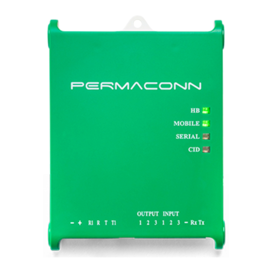
- 8 LED Status Indicators
- 9 Contact ID Reporting Codes
- 10 PM24 Specifications
- 11 Warning / Liability
- Download this manual
Advertisement
Table of Contents

Summary of Contents for Permaconn PM24
- Page 1 PERMACONN PM24 Installation Manual RDCCO PTY LTD Unit 3/9-11 South St Rydalmere NSW 2116 Telephone: 61 2 9352 1777 Web: www.permaconn.com...
-
Page 2: Table Of Contents
Table of Contents Introduction / Features of the PM24 / Data Plans............3 Atlas Web Platform / Installation Procedure..............4 Programming the Alarm Panel / Antenna Installation ..........5 Powered from Alarm Panel / Defaulting the PM24............6 Outputs / Inputs ......................7 Securitel Interface / Transmission Delay Times............8 LED Status Indicators....................9... -
Page 3: Introduction / Features Of The Pm24 / Data Plans
Introduction The Permaconn system provides two-way communication between supervised premises and the Monitoring Centre. The PM24 is a versatile state of the art microprocessor based LTE CAT M1 security communicator. This unit can inter- face with a range of alarm panels using serial or Contact ID. -
Page 4: Atlas Web Platform / Installation Procedure
fore applying power. The PM24 will not operate unless it has been activated. Place the PM24 housing in the space where you intend to install it. Do not mount the PM24 yet, as it may need to be moved to obtain a better signal strength Screw the antenna onto the SMA connector. -
Page 5: Programming The Alarm Panel / Antenna Installation
When a valid Contact ID event is sent from the alarm panel the ‗CID‘ LED = [Green - Steady On]. Ping the PM24 using Atlas to verify status of installation. Antenna Installation Antennas can have their performance maximised using a ―Ground Plane‖, any metal mounting surface will suffice. -
Page 6: Powered From Alarm Panel / Defaulting The Pm24
PM24 - Powered from Alarm Panel Defaulting the PM24 Apply DC power and depress reset button for: Three (3) seconds to reset CAT M1 settings. Green LEDs will all flash Green together to confirm successful default. PM24 Installation Manual v1.1... -
Page 7: Outputs / Inputs
Outputs are ‗Open Collector‘ @50mA switching 12vDC negative—for heavier loads a relay must be used. Ensure there is a common negative between the PM24 and the device being switch. The outputs can be opened, closed or pulsed using the Atlas web portal ... -
Page 8: Securitel Interface / Transmission Delay Times
Serial Interface ‗Serial‘ MUST be selected on activation otherwise it will not operate. The PM24 comes standard with Securitel / serial interfaces to suit: Tecom MCM Icon C & K ( Sierra STU ) Siemens Cardax / Gallagher (IFM-CDX required) ... -
Page 9: Led Status Indicators
Alarm panel has sent a valid CID event Red On Dialler lead not connected (No return line R1&T1) LED Off Normal status when panel off hook Orange Events sent but R1 & T1 did not restore PM24 Installation Manual v1.1 RDCCO_2204_E_IN... -
Page 10: Contact Id Reporting Codes
Auxiliary 3 – Auxiliary input alarm on Permaconn com- municator. Panel ID Clash— When two (2) Permaconn devices are reporting to the same Control Room on the same line number using the same ac- count number. Check in Atlas for duplicate account number. -
Page 11: Pm24 Specifications
EN 301 489-1 V 2.1.1 (2017-02), Draft ETSI EN 301 489-52 V1.1.0 (2016-11) ETSI EN 301 908-1 V11.1.1(2016-07), ETSI EN 301 908-2 V11.1.1(2016-07) ETSI EN 301 908-1 V11.1.1 (2016-07), ETSI EN 301 908-13 V11.1.1 (2016-07), EN62479: 2010 EN 60950-1:2006+A11:2009+A1:2010+A12: 2011+A2:2013 PM24 Installation Manual v1.1 RDCCO_2204_E_IN... -
Page 12: Warning / Liability
The socket-outlet must be installed near the equipment and easily accessible. The unit must only be operated with the supplied antenna. Install the PM24 in a loca- tion that no person[s] is closer than 200 mm to the antenna at all times.
Need help?
Do you have a question about the PM24 and is the answer not in the manual?
Questions and answers