Table of Contents
Advertisement
Quick Links
Advertisement
Chapters
Table of Contents

Related Manuals for Phoenix Contact BL2 PPC

Summary of Contents for Phoenix Contact BL2 PPC
- Page 1 BL2 PPC industrial PC for IP65 environments User manual UM EN BL2 PPC AIO65...
- Page 2 UM EN BL2 PPC AIO65, Revision A 2020-03-09 This user manual is valid for: Designation Order No. BL2 PPC AIO65 2000 1138366 BL2 PPC AIO65 7000 1138367 PHOENIX CONTACT GmbH & Co. KG • Flachsmarktstraße 8 • 32825 Blomberg • Germany phoenixcontact.com...
-
Page 3: Table Of Contents
VESA mount housing ................15 5.1.2 CS3000 mount ..................16 Real-time clock battery ..................16 5.2.1 Battery disposal ..................17 UEFI reset......................18 UEFI ........................19 Technical appendix........................21 Technical data ....................21 Appendixes..........................25 List of figures ...................... 25 List of tables ....................... 27 1/32 4065_en_A PHOENIX CONTACT... - Page 4 BL2 PPC…AIO65… 2/32 PHOENIX CONTACT 4065_en_A...
-
Page 5: For Your Safety
Any modifications to the systems can influence the EMC behavior. The device contains valuable recyclable materials, which should be utilized. The elec- tronic circuit board is fitted with a lithium battery. Dispose of the device separately from other waste, i.e., via an appropriate collection site. 3/32 4065_en_A PHOENIX CONTACT... -
Page 6: Product Changes
BL2 PPC…AIO65… 1.3.2 Product changes Changes or modifications to hardware and software of the device are not permitted. Incorrect operation or modifications to the device can endanger your safety or damage the device. Do not repair the device yourself. If the device is defective, please contact Phoenix Contact. -
Page 7: Overview And Ordering Data
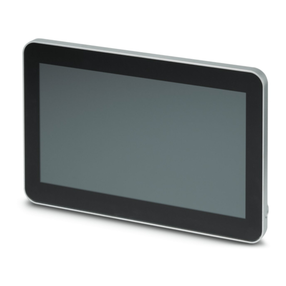
Description ® The BL2 PPC…AIO65… IPC is a configurable panel PC (PPC) that utilizes the Intel processors chosen for their balance of processing power, graphic performance, and energy efficiency. The robust design and I/O capability make the BL2 PPC…AIO65… a product that can be used in a wide variety of applications. - Page 8 BL2 PPC…AIO65… 6/30 PHOENIX CONTACT 4065_en_A...
-
Page 9: Installation
3.1.1 VESA The BL2 PPC AIO65... conforms to the VESA, MIS-D, 100, C hole pattern. Note that this standard is for devices up to 14 kg (30 lb.). Because the housing must be opened to route the cables through grommets and attach them to the ports, cables should be installed and attached to the PC before attaching the PC to the VESA mount. -
Page 10: Accessing Ports In A Vesa-Mount Configuration
BL2 PPC…AIO65… To install a cable: Loosen the captive screws (1) securing the rear cover (2) to the IPC and panel assembly (3) and carefully raise the cover. Note that ground (4) and USB (5) cables are connected internally and must be disconnected to fully separate the components. -
Page 11: Cs3000 Mount
Installation 3.1.2 CS3000 mount The BL2 PPC…AIO65… may be configured for attachment to a Bernstein CS3000 adapter, either top or bottom mount. A push-button housing may be incorporated into the unit when the adapter is attached to the bottom. Figure 3-2... -
Page 12: Interfaces
If applicable, install desired buttons in the push-button housing. Interfaces Connections to the circuit board are made with the rear cover removed. WARNING: Always remove power before removing the rear cover of the BL2 PPC…AIO65…. X4: USB X6: USB X1: PWR 24VDC... -
Page 13: Power Connection
BL2 PPC…AIO65…. Figure 3-4 Power connector The power supply to the BL2 PPC…AIO65… must incorporate a switch in the supply within reach of the IPC. Connect a power source to the included power connector. This connector supports wire sizes from 0.2 to 2.5 mm²... -
Page 14: Serial Communication
RS-232, RS-422, or RS-485 physical layer. The physical layer is set using the UEFI (see “UEFI” on page 22). The remaining connectors are limited to RS-232 only. The BL2 PPC…AIO65… is capable of the following communication parameters: Table 3-3 RS-232/422/485 communication settings... -
Page 15: Operation
Status LEDs are for troubleshooting only as they are not visible during normal operation. The rear half of the housing must be removed to view the status LEDs. Four LEDs are provided on the BL2 PPC…AIO65…. These LEDs provide operating information (see Figure 3-3 on page 10). - Page 16 BL2 PPC…AIO65… 14/30 PHOENIX CONTACT 4065_en_A...
-
Page 17: Maintenance
Maintenance Maintenance Opening the housing The BL2 PPC…AIO65… is a PC inside a IP65-rated housing. To access the ports and internal PC components, the housing must be opened. 5.1.1 VESA mount housing Remove power to the device. Loosen the captive screws (1) securing the rear cover (2) to the IPC and panel assembly (3) and carefully raise the cover. -
Page 18: Cs3000 Mount
The battery supplies power to the real-time clock (RTC) and maintains the UEFI settings in the BL2 PPC…AIO65… when the system is not connected to a 24 V DC power source. If power is removed while the battery is discharged or removed, any user-defined UEFI settings will be lost, and a “CMOS checksum error”... -
Page 19: Battery Disposal
Directive 2006/66/EC addresses disposal of batteries in the European Union. In the U.S., it is regulated by individual states. NOTE: To prevent short circuitry in the collection boxes, insulate the poles of each battery with insulation tape or put each single battery into a plastic bag. 17/32 4065_en_A PHOENIX CONTACT... -
Page 20: Uefi Reset
The UEFI reset buttons are intended to be used only by advanced users or if directed to do so by Phoenix Contact technical service. After the reset, the UEFI will need to be reconfigured to account for any user-defined settings. -
Page 21: Uefi
USB drive. Press the <F12> key during the boot process to access the quick-boot menu. Highlight the device from which to boot. Press the <Enter> key to initiate the boot process. 19/32 4065_en_A PHOENIX CONTACT... - Page 22 BL2 PPC…AIO65… 20/32 PHOENIX CONTACT 4065_en_A...
-
Page 23: A Technical Appendix
0.2 … 2.5 mm² (20 … 12 AWG) Torque, wire clamping screw 0.5 … 0.6 Nm RTC battery, typical life BR2032, 5 years Current and power data BL2 PPC... AIO 2000 BL2 PPC... AIO65 7000 † Current consumption @ 24 V, maximum with 15.6-in. display 2.06 A 2.69 A... - Page 24 Number of bays RAID support None Main memory RAM, maximum 8 GB Type DDR3L Processor data BL2 PPC... AIO65 2000 BL2 PPC... AIO65 7000 Processor Intel Pentium N4200 Intel Core i5-7442EQ Clock speed 1.10 GHz 2.10 GHz 2.50 GHz 2.90 GHz...
- Page 25 EN 61000-4-2:1995+ A1:1998 +A2:2002 (ESD) EN 61000-4-4:2004 (EFT/Burst) EN 61000-4-5:1995+ A1:2001 (Surge immunity) EN 61000-4-8:1993/A1:2001 (Magnetic immunity) EN 61000-4-11:2004 (Voltage dips, short interruptions, and voltage immunity tests Approvals CE compliant FCC Part 15 Class A UL/cUL UL 61010 23/30 4065_en_A PHOENIX CONTACT...
- Page 26 BL2 PPC…AIO65… 24/30 PHOENIX CONTACT 4065_en_A...
-
Page 27: Appendixes
Figure 3-3: Connectors and ports .................10 Figure 3-4: Power connector .................11 Section 5 Figure 5-1: Accessing ports in a VESA-mount configuration .........15 Figure 5-2: CS3000-mount configuration ..............16 Figure 5-3: Battery location ...................17 Figure 5-4: UEFI jumpers ..................18 25/32 4065_en_A PHOENIX CONTACT... - Page 28 BL2 PPC…AIO65… 26/32 PHOENIX CONTACT 4065_en_A...
-
Page 29: List Of Tables
List of tables List of tables Section 3 Table 3-1: Minimum and maximum cable sizes ............7 Table 3-2: Power connector..................11 Table 3-3: RS-232/422/485 communication settings ..........12 Table 3-4: D-SUB 9 pinout..................12 Section 4 Table 4-1: LED indications..................13 27/32 4065_en_A PHOENIX CONTACT... - Page 30 BL2 PPC…AIO65… 28/32 PHOENIX CONTACT 4065_en_A...
- Page 31 The receipt of technical documentation (in particular user documentation) does not constitute any further duty on the part of Phoenix Contact to furnish information on modifications to products and/or technical documentation. You are responsible to verify the suitability and intended use of the products in your specific application, in particular with regard to observing the applicable standards and regulations.
- Page 32 Middletown, PA 17057 Should you have any suggestions or recommendations for improvement of the contents and layout of our manuals, please send your comments to: tecdoc@phoenixcontact.com 30/30 PHOENIX CONTACT GmbH & Co. KG • Flachsmarktstraße 8 • 32825 Blomberg • Germany phoenixcontact.com...
Need help?
Do you have a question about the BL2 PPC and is the answer not in the manual?
Questions and answers