
Related Manuals for axing OTX 51-00

Summary of Contents for axing OTX 51-00
- Page 1 OTX 51-00 ORX 14-00 | ORX 14-01| ORX 15-00 Optischer Sender | Optische Empfänger Betriebsanleitung...
- Page 2 Inhaltsverzeichnis...
- Page 3 ...
- Page 4 1. Produktbeschreibung 1.1. Allgemein 1.1.1. OTX 51-00 1.1.2. ORX 14-00 | ORX 14-01 | ORX 15-00 ∂ ∂ ∂...
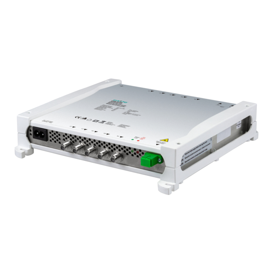
- Page 5 1.2. Lieferumfang ∂ ∂ ∂ ∂ ∂ 1.3. Zubehör 1.4. Anzeigeelemente und Anschlüsse 1.4.1. OTX 51-00...
- Page 6 1.4.2. Anschlüsse ORX 14-00 | ORX 14-01 | ORX 15-00 1.4.3. Betriebsanzeigen ORX 14-00 | ORX 14-01 | ORX 15-00 ∂ ∂ ∂ ∂ ∂...
-
Page 7: Montage Und Anschluss
2. Montage und Anschluss 2.1. Montage nicht 2.2. Potentialausgleich ... - Page 8 2.3. HF-Anschluss 2.3.1. Eingänge des Senders Messbuchsen ...
- Page 9 2.3.2. Ausgänge der Empfänger ORX 15-00 Ausgänge ORX 14-00 Teilnehmeranschlüsse ...
- Page 10 ORX 14-01 Teilnehmeranschlüsse 2.4. Optischer Anschluss Es darf keine direkte optische Verbindung zwischen Sender und Empfänger hergestellt werden. Steckverbindung herstellen oder lösen ...
- Page 11 2.5. Stromversorgung 2.5.1. OTX 51-00 2.5.2. ORX 14-00 und 15-00 Hinweis: 2.5.3. ORX 14-01...
- Page 12 3. Planung einer optischen Installation 3.1. Dimensionierung -8 dBm -14 dBm +7,5 dBm Hinweise: ∂ ∂ 3.2. Eingangssignale des optischen Senders 3.2.1. SAT-Eingangspegel 3.2.2. SAT-Frequenzgang 3.2.3. Kaskadierung mehrere OTX 51-00 3.2.4. TERR (DVB-T/-T2/-C) ≤ ∂ μ ∂ μ ∂ μ 3.2.5. TERR (FM/DAB)
- Page 13 3.3. Ausgangspegel der optischen Empfänger 3.3.1. ORX 14-00 SAT-Ausgangspegel Terrestrische Ausgangspegel (DVB-T/-T2/-C) 3.3.2. ORX 14-01 SAT-Ausgangspegel (SCR/CSS) ∂ Terrestrische Ausgangspegel (DVB-T/-T2/-C) 3.3.3. ORX 15-00 SAT-Ausgangspegel (typisch) ∂ ∂ Terrestrische Ausgangspegel (DVB-T/-T2/-C) TERR (FM/DAB)
- Page 14 3.4. Installationsbeispiele 3.4.1. Optische Verteilung an mehrere ORX-Empfänger...
- Page 15 3.4.2. Kaskade von mehreren OTX 51-00...
-
Page 16: Technische Daten
Betriebsanleitung | OTX 51-00 | ORX 14-00 | ORX 14-01| ORX 15-00 4. Technische Daten 4.1. OTX 51-00 OTX 51-00 Eingänge Anzahl Frequenzbereich 87 … 862 MHz @ DVB-C/T/T2 950 … 2150 MHz @ DVB-S/S2/S2X Anzahl Kanäle (DVB-C/T/T2) max. 16 Eingangspegel 74 …... - Page 17 4.2. ORX 14-00 und ORX 14-01 ORX 14-00 ORX 14-01 Eingang Optischer Anschluss SC/APC Optischer Pegel −14 … −8 dBm Wellenlänge 1290 … 1580 nm Optische Rückflussdämpfung > 45 dB Teilnehmeranschlüsse Anzahl 4 × LEGACY (SAT + TERR) 2 × SCR (TERR + 16 UB) 2 ×...
- Page 18 Betriebsanleitung | OTX 51-00 | ORX 14-00 | ORX 14-01| ORX 15-00 4.3. ORX 15-00 ORX 15-00 Eingang Optischer Anschluss SC/APC Optischer Pegel −14 … −8 dBm Wellenlänge 1310 nm Optische Rückflussdämpfung > 45 dB Ausgang TERR | VL | VH | HL | HH Pegel @ 21 dB otischer Dämpfung...
- Page 21 OTX 51-00 ORX 14-00 | ORX 14-01| ORX 15-00 Optical Transmitter | Optical Receivers Operation instructions...
- Page 22 Table of contents...
- Page 23 ...
-
Page 24: Product Description
1. Product description 1.1. General 1.1.1. OTX 51-00 1.1.2. ORX 14-00 | ORX 14-01 | ORX 15-00 ∂ ∂ ∂... - Page 25 1.2. Scope of delivery ∂ ∂ ∂ ∂ ∂ 1.3. Accessories Display elements and connectors 1.4. 1.4.1. OTX 51-00...
- Page 26 1.4.2. Connectors of ORX 14-00 | ORX 14-01 | ORX 15-00 1.4.3. Operating-LED of ORX 14-00 | ORX 14-01 | ORX 15-00 ∂ ∂ ∂ ∂ ∂...
-
Page 27: Mounting And Installation
2. Mounting and Installation 2.1. Mounting 2.2. Equipotential bonding ... - Page 28 2.3. RF Installation 2.3.1. Transmitter inputs Test ports...
- Page 29 2.3.2. Receiver outputs ORX 15-00 outputs ORX 14-00 subscriber ports ...
-
Page 30: Optical Installation
ORX 14-01 subscriber ports 2.4. Optical installation No direct optical connection may be established between the transmitter and receiver. Connecting or disconnecting the plug connection ... - Page 31 2.5. Power supply 2.5.1. OTX 51-00 2.5.2. ORX 14-00 and 15-00 Note: 2.5.3. ORX 14-01...
- Page 32 3. Planning an optical installation 3.1. Dimensioning -8 dBm -14 dBm ∂ ∂ 3.2. Input signals of the optical transmitter 3.2.1. SAT input signal level 3.2.2. SAT flatness 3.2.3. Cascading several OTX 51-00 3.2.4. TERR (DVB-T/-T2/-C) ≤ ∂ ∂ 3.2.5. TERR (FM/DAB)
- Page 33 3.3. Output levels of the optical receivers 3.3.1. ORX 14-00 SAT output level Terrestrial output level (DVB-T/-T2/-C) 3.3.2. ORX 14-01 SAT output level (SCR/CSS) ∂ Terrestrial output level (DVB-T/-T2/-C) 3.3.3. ORX 15-00 SAT output level (typical) ∂ ∂ Terrestrial output level (DVB-T/-T2/-C) μ...
-
Page 34: Installation Examples
3.4. Installation examples 3.4.1. Optical distribution to several ORX... - Page 35 3.4.2. Cascading of several OTX 51-00...
-
Page 36: Technical Data
Operation instructions | OTX 51-00 | ORX 14-00 | ORX 14-01| ORX 15-00 4. Technical data 4.1. OTX 51-00 Type OTX 51-00 Inputs Number Frequency range 87 … 862 MHz @ DVB-C/T/T2 950 … 2150 MHz @ DVB-S/S2/S2X number of channels (DVB-C/T/T2) max. - Page 37 4.2. ORX 14-00 and ORX 14-01 Type ORX 14-00 ORX 14-01 Input Optical connector SC/APC Optical level −14 … −8 dBm Wavelength 1290 … 1580 nm Optical return loss > 45 dB Subscriber ports Number Type 4 × LEGACY (SAT + TERR) 2 ×...
- Page 38 Operation instructions | OTX 51-00 | ORX 14-00 | ORX 14-01| ORX 15-00 4.3. ORX 15-00 Type ORX 15-00 Input Optical connector SC/APC Optical level −14 … −8 dBm Wavelength 1310 nm Optical return loss > 45 dB Output Type...
Need help?
Do you have a question about the OTX 51-00 and is the answer not in the manual?
Questions and answers