
Subscribe to Our Youtube Channel
Related Manuals for Wöhner Motus C14


Summary of Contents for Wöhner Motus C14
- Page 1 MOTUS®C14 Operating Instructions English. Page 1 of 53 94 762 000 B Revision 03.2021...
-
Page 2: Table Of Contents
Deutsch. MOTUS®C14 Bedienungsanleitung Inhaltsverzeichnis Inhaltsverzeichnis ..................2 Beschreibung ................... 4 Applikationsbeispiele ................4 Zulässige Applikationen ......................4 Verbotene Applikationen ......................5 Bestelldaten ..................... 5 Sicherheitsbestimmungen und Errichtungshinweise ........ 7 Inhalt der EU-Konformitätserklärung ..................7 Errichtungshinweise ........................ 7 Anwendungsbereich ........................ 8 UL-Hinweis .......................... - Page 3 Deutsch. MOTUS®C14 Bedienungsanleitung 15 Auslösekennlinie (kalter Zustand) ............18 16 Auslösekennlinie (warmer Zustand) ............19 17 Abkühlzeiten ................... 20 18 Zulässige Überstromfaktoren ..............21 19 Derating ....................22 20 IO-Link Interface ..................23 20.1 Process Data In (PDIN) ......................23 20.2 Process Data Out (PDOUT) ....................
-
Page 4: Beschreibung
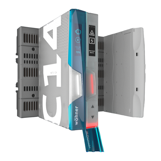
Deutsch. MOTUS®C14 Bedienungsanleitung Beschreibung ® Der 3-phasige Motorstarter MOTUS C14 ist ein kompaktes Schaltgerät mit 22,5 mm Baubreite. Der elektronische Motorstarter beinhaltet folgende Funktionsblöcke: Rechtslauf Linkslauf Direkt- und Wendestart Motor-Überlastschutz Elektronischer Kurzschlussschutz ohne Sicherungstausch Galvanische Unterbrechung ... -
Page 5: Verbotene Applikationen
Deutsch. MOTUS®C14 Bedienungsanleitung 3.2 Verbotene Applikationen Bild 2 Verbotene Schaltungsvarianten Der elektronische Motorstarter ist nicht für die Kombination mit einem Frequenzumrichter geeignet. Die typischen Strom- und Spannungsformen eines Frequenzumrichters können zur unbeabsichtigten Auslösung der internen Schutzmechanismen führen. Bestelldaten Elektronikbaustein Beschreibung Gewicht Art.-Nr. - Page 6 Deutsch. MOTUS®C14 Bedienungsanleitung Elektronikbaustein Beschreibung Gewicht Art.-Nr. kg/100 MOTUS®C14 Motorstarter mit IO-Link und Display; 36 255 Connect Plus Funktionen: Motor starten, Motor 2,6 A reversieren, Motorschutz, Panel Kurzschlussschutz; einstellbare Auslöseklasse MOTUS®C14 Motorstarter mit IO-Link und Display; 36 256 Connect Plus Funktionen: Motor starten, Motor 2,6 A reversieren, Motorschutz,...
-
Page 7: Sicherheitsbestimmungen Und Errichtungshinweise
Deutsch. MOTUS®C14 Bedienungsanleitung Sicherheitsbestimmungen und Errichtungshinweise 5.1 Inhalt der EU-Konformitätserklärung Hersteller: Wöhner GmbH & Co. KG, Mönchrödener Straße 10, 96472 Rödental, Germany Die aktuelle EU-Konformitätserklärung steht Ihnen beim jeweiligen Artikel als Download auf unserer Homepage www.woehner.de zur Verfügung. 5.2 Errichtungshinweise ... -
Page 8: Anwendungsbereich
Deutsch. MOTUS®C14 Bedienungsanleitung 5.3 Anwendungsbereich Dies ist ein Produkt für Umgebung A (Industrie): in Umgebung B (Haushalt) kann dieses Gerät unerwünschte Funkstörungen verursachen. In diesem Fall kann der Anwender verpflichtet sein, angemessene Maßnahmen durchzuführen. 5.4 UL-Hinweis Warnung: Gefahr durch elektrischen Schlag und Brandgefahr! ... -
Page 9: Bedien- Und Anzeigeelemente
Deutsch. MOTUS®C14 Bedienungsanleitung Bedien- und Anzeigeelemente Steuerstecker Haupttaster Laststecker Sammelschienenadapter 30Compact USB-C Buchse ® Bild 3 Bedien- und Anzeigeelemente MOTUS C14 Connect Steuerstecker Haupttaster Laststecker Sammelschienenadapter 30Compact Display Pfeiltaster USB-C Buchse ® Bild 4 Bedien- und Anzeigeelemente MOTUS C14 Connect Plus Seite 9 von 53 94 762 000 B Revision 03.2021... -
Page 10: Anschlüsse
Deutsch. MOTUS®C14 Bedienungsanleitung Anschlüsse Warnung: Lebensgefahr durch Stromschlag! Niemals bei anliegender Spannung arbeiten 7.1 Netzanschluss und Leitungsschutz Beachten Sie beim Anschluss des 3-Phasen-Netzes unbedingt die Klemmenbezeichnung. Betreiben Steuerspeisespannungs- Steuerspannungseingänge Stromversorgungsmodulen gemäß IEC 61131-2 (max. 5 % Restwelligkeit). Um bei langen Steuerleitungen die induktive bzw. -
Page 11: Standard-Anschluss
Deutsch. MOTUS®C14 Bedienungsanleitung 7.3 Standard-Anschluss Die Standard-Verbindung wird über einen 16-poligen Steckverbinder realisiert. Schließen Sie die Leitungen an den Steckverbinder am Motorstarter an. Um den an das Gerät angeschlossenen Motor in Betrieb zu setzen, müssen Sie dem Gerät über den Enable-Eingang die Freigabe erteilen. ... -
Page 12: Leitungen Anschließen
Deutsch. MOTUS®C14 Bedienungsanleitung 7.5 Leitungen anschließen 7.5.1 Schraubanschluss Bild 7 Schraubanschluss Isolieren Sie die Einzeladern um 8 mm ab. Stecken Sie den Leiter in die entsprechende Anschlussklemme Ziehen Sie die Schraube in der Öffnung über der Anschlussklemme mit einem Schraubendreher fest. -
Page 13: Eplan-Symbol
Deutsch. MOTUS®C14 Bedienungsanleitung Eplan-Symbol ® Bild 9 Eplan-Symbol MOTUS ServiceTool Mit Hilfe des ServiceTools kann der MOTUS®C14 am PC konfiguriert werden. Die Verbindung zwischen Gerät und PC erfolgt über ein USB-Kabel. Die aktuelle Version des ServiceTools kann jeweils unter folgendem Link heruntergeladen werden: https://www.motus-c14.de/de/servicetool ... -
Page 14: Menüführung
Deutsch. MOTUS®C14 Bedienungsanleitung Menüführung Mit Hilfe des Haupttasters (1) navigieren Sie durch das Hauptmenü. Dieses besteht aus einem Homescreen, einem Einstellungsmenü drei Messscreens. Mit Hilfe der Pfeiltaster (2 und 3) können Sie durch das Einstellungsmenü scrollen Einstellungen Hilfe Haupttasters (1) vornehmen. -
Page 15: Warnungen Und Störungen
Deutsch. MOTUS®C14 Bedienungsanleitung Warnungen und Störungen 11.1 Warnungen W1402 Unterstrom Last (einstellbar) W1403 Überspannung Versorgung AC (einstellbar) W1404 Unterspannung Versorgung AC (einstellbar) W1405 Übertemperatur Gerät (>60 °C) W1406 Überlast Motor (abhängig von Auslöseklasse und Nennstrom) W1407 Asymmetrische Last (>33 %) W1408 Phasenausfall Last W1409... -
Page 16: Zurücksetzen Auf Werkseinstellungen
Deutsch. MOTUS®C14 Bedienungsanleitung Zurücksetzen auf Werkseinstellungen Es ist möglich das Gerät über das ServiceTool oder das Display in die Werkseinstellungen zurückzusetzen. Nennstrom - Auslöseklasse Kombinationen 2,6 A Nennstrom TC 2E TC 3E TC 5 TC 10A TC 10 TC 20 TC 30 TC 40E 0,1 A... -
Page 17: Nennstrom - Auslöseklasse Kombinationen 6,6 A
Deutsch. MOTUS®C14 Bedienungsanleitung Nennstrom - Auslöseklasse Kombinationen 6,6 A Nennstrom TC 2E TC 3E TC 5 TC 10A TC 10 TC 20 TC 30 TC 40E 0,1 A 0,2 A 0,3 A 0,4 A 0,5 A 0,6 A 0,7 A 0,8 A 0,9 A 1,0 A... -
Page 18: Auslösekennlinie (Kalter Zustand)
Deutsch. MOTUS®C14 Bedienungsanleitung Auslösekennlinie (kalter Zustand) 1000 10 A Überstrom I/I Bild 13 Auslösezeiten (kalter Zustand) Tabelle 1: Auslösezeiten [hh:mm:ss] (kalter Zustand) I / I TC 2E TC 3E TC 5 TC 10A TC 10 TC 20 TC 30 TC 40E 00:02:02 00:03:23 00:06:06 00:08:08 00:10:50 00:24:23 00:37:56 00:51:29 00:00:43 00:01:12 00:02:09 00:02:52 00:03:50 00:08:37 00:13:25 00:18:12 00:00:20 00:00:33 00:00:59 00:01:18 00:01:44 00:03:54 00:06:05 00:08:15... -
Page 19: Auslösekennlinie (Warmer Zustand)
Deutsch. MOTUS®C14 Bedienungsanleitung Auslösekennlinie (warmer Zustand) 1000 Überstrom I/I Bild 14 Auslösezeiten (warmer Zustand) Tabelle 2: Auslösezeiten [hh:mm:ss] (warmer Zustand) I / I TC 2E TC 3E TC 5 TC 10A TC 10 TC 20 TC 30 TC 40E 00:01:04 00:01:47 00:03:13 00:04:17 00:05:43 00:12:51 00:20:00 00:27:15 00:00:15 00:00:24 00:00:44 00:00:58 00:01:17 00:02:54 00:04:31 00:06:11 00:00:06 00:00:09 00:00:17 00:00:22 00:00:30 00:01:06 00:01:43 00:02:21 00:00:02 00:00:03 00:00:06 00:00:08 00:00:11 00:00:24 00:00:37 00:00:51... -
Page 20: Abkühlzeiten
Deutsch. MOTUS®C14 Bedienungsanleitung Abkühlzeiten 100% Abkühlzeit [min] Bild 15 Abkühlzeiten Tabelle 3: Abkühlzeiten [hh:mm:ss] Therm. G. TC 2E TC 3E TC 5 TC 10A TC 10 TC 20 TC 30 TC 40E 100 – 75 % 00:00:42 00:01:10 00:02:06 00:02:48 00:03:44 00:08:24 00:13:04 00:17:44 100 –... -
Page 21: Zulässige Überstromfaktoren
Deutsch. MOTUS®C14 Bedienungsanleitung Zulässige Überstromfaktoren Zulässiger wiederholbarer Überstromfaktor zu Bemessungsbetriebsstrom (AC-53a) MOTUS®C14 2,6 A MOTUS®C14 6,6 A Bemessungsbetriebsstrom des Abzweiges I in A Bild 16 Zulässiger wiederholbarer Überstromfaktor zu Bemessungsbetriebsstrom Der Anlaufstrom der Last soll 56 A (6,6A Gerät) bzw. 35 A (2,6A Gerät) nicht übersteigen ... -
Page 22: Derating
Deutsch. MOTUS®C14 Bedienungsanleitung Derating 2,6 A-Geräte: Gerät senkrecht, Motorabgang unten Umgebungstemperatur [°C] Max. Laststrom [A], angereiht mit Abstand ≥22,5 mm Max. Laststrom [A], angereiht ohne Abstand 6,6 A-Geräte: Gerät senkrecht, Motorabgang unten (dynamische Lüfterregelung) Umgebungstemperatur [°C] Max. Laststrom [A], angereiht mit Abstand ≥22,5 mm Max. -
Page 23: Io-Link Interface
Deutsch. MOTUS®C14 Bedienungsanleitung IO-Link Interface 20.1 Process Data In (PDIN) Byte Bit offset Name Datatype Bit 7: reserved bool Bit 6: reserved Bit 5: Softstart active Bit 4: External enable signal Bit 3: Counterclockwise rotation Bit 2: Clockwise rotation Bit 1: Warning detected Bit 0: Error detected Bit 7: reserved Bit 6: reserved... -
Page 24: Process Data Out (Pdout)
Deutsch. MOTUS®C14 Bedienungsanleitung Bit 7: reserved enum Bit 6: reserved Bit 5: reserved Bit 4: reserved Bit 3…0: Device Type 0: Motorstarter C14 Connect Plus 2,6 A 1: Motorstarter C14 Connect Plus 6,6 A 2: Motorstarter C14 Connect Plus 8,5 A 3: Motorstarter C14 Connect 2,6 A 4: Motorstarter C14 Connect 6,6 A 5: Motorstarter C14 Connect 8,5 A... -
Page 25: Application Specific Parameters
Deutsch. MOTUS®C14 Bedienungsanleitung 20.4 Application specific parameters Index Data Length Access Name Description Default Unit Type Value Nominal Current Maximum uint 1 Byte 1 = 100 value 26 / 66 uint 1 Byte Trip class 0: Class 2E 1: Class 3 2: Class 5 3: Class 10A 4: Class 10... -
Page 26: Technische Daten
Deutsch. MOTUS®C14 Bedienungsanleitung Technische Daten Geräteversorgung Bemessungssteuerstromkreisspeisespannung U 24 V DC Steuerspeisespannungsbereich 20,4 V DC - 26,4 V DC Bemessungssteuerspeisestrom I 200 mA Schutzbeschaltung Überspannungsschutz Verpolschutz Digitaler Eingang gemäß IEC 60947-1 Anhang S Bemessungsbetätigungsspannung U 24 V DC Bemessungsbetätigungsstrom I 7 mA <... - Page 27 Deutsch. MOTUS®C14 Bedienungsanleitung Anschlussdaten Benennung Anschluss Steuerkreis Anschlussart Push-in-Anschluss Leiterquerschnitt feindrähtig ohne Aderendhülse 0,2 - 1,5 mm² Leiterquerschnitt feindrähtig mit Aderendhülse 0,25 - 1,5 mm² Leiterquerschnitt feindrähtig mit isolierter 0,14 - 0,75 mm² Aderendhülse Leiterquerschnitt starr 0,2 - 1,5 mm² Abisolierlänge 10 mm Benennung Anschluss...
-
Page 28: Table Of Contents
MOTUS®C14 Operating Instructions English. Table of contents Table of contents ..................28 Description ....................30 Applications .................... 30 Allowed applications ......................30 Forbidden applications ......................31 Ordering Data ..................31 Safety regulations / installation notes ............. 33 Content EU-Declaration of Conformity ................. 33 Area of application ........................ - Page 29 MOTUS®C14 Operating Instructions English. 17 Overload cool down times............... 46 18 Permitted overcurrent factors ..............47 19 Derating ....................48 20 IO-Link interface ..................49 20.1 Process Data In (PDIN) ......................49 20.2 Process Data Out (PDOUT) ....................50 20.3 Predefined ISDU parameters ....................
-
Page 30: Description
MOTUS®C14 Operating Instructions English. Description ® The 3-phase Motor starter MOTUS C14 is a compact switching device with 22,5 mm width. The electronic Motor starter includes the following functions: Operation mode: right rotation Operation mode: left rotation Direct- / Reverse Start ... -
Page 31: Forbidden Applications
MOTUS®C14 Operating Instructions English. 3.2 Forbidden applications Image 2 Combination with frequency inverter The electronic motor starter can´t be used in combination with frequency inverters. The typical current and voltage waveforms of a frequency inverter might lead to accidental triggering of internal safety mechanisms. - Page 32 MOTUS®C14 Operating Instructions English. Product Description Weight Part designation kg/100 MOTUS®C14 Motor starter with IO-Link; Functions: 36 255 Connect Plus Start Motor, Reverse Start Motor, 2,6 A Overload Protection, Short Circuit Panel Protection; Selectable Trip Class MOTUS®C14 Motor starter with IO-Link; Functions: 36 256 Connect Plus Start Motor, Reverse Start Motor,...
-
Page 33: Safety Regulations / Installation Notes
MOTUS®C14 Operating Instructions English. Safety regulations / installation notes 5.1 Content EU-Declaration of Conformity Manufacturer: Wöhner GmbH & Co. KG, Mönchrödener Straße 10, 96472 Rödental, Germany The valid EU-Declaration of Conformity can be found in the download section linked to the product code on the Wöhner Homepage, https://www.woehner.com Safety regulations and installation notes... -
Page 34: Ul Notes
MOTUS®C14 Operating Instructions English. 5.3 UL notes WARNING: Risk of electrical shock and fire The opening of the branch-circuit protective device may be an indication that a fault current has occurred. To reduce the risk of fire or electric shock, current-carrying parts and the other components of the controller should be examined and replaced if damaged. -
Page 35: Operating And Indication
MOTUS®C14 Operating Instructions English. Français. Operating and indication Control plug Main button Load plug Busbar adapter USB Type-C receptable ® Image 3 Operating and indication for MOTUS C14 Connect Control plug Main button Load plug Busbar adapter Display Selector buttons USB Type-C receptable Page 35 of 53 94 762 000 B... -
Page 36: Connections
MOTUS®C14 Operating Instructions English. ® Image 4 Operating and indication for MOTUS C14 Connect Plus Connections WARNING: Danger to life by electric shock Never carry out work when voltage is present. 7.1 Main connection and line protection When making the phase connection, it is essential to observe the terminal identification. ... -
Page 37: Standard Connection
MOTUS®C14 Operating Instructions English. 7.3 Standard connection The standard connection is made using a 16-pin connector. Connect the cables to the control plug of the motor starter. To put the motor into operation, you have to enable the device via the enable input. ... -
Page 38: Connecting The Cables
MOTUS®C14 Operating Instructions English. 7.5 Connecting the cables 7.5.1 Screw connection Image 7 Screw connection Strip 8 mm of insulation from the individual wires. Plug the conductor into the corresponding terminal block. Tighten the screw in the opening above the connection terminal with a screwdriver. 7.5.2 Push-in connection Image 8 Push-in connection... -
Page 39: Eplan Symbol
MOTUS®C14 Operating Instructions English. Eplan symbol ® Image 9 Eplan symbol MOTUS ServiceTool The MOTUS®C14 can be configured using a PC via the ServiceTool. The connection between the device and PC is established via a USB-cable. The current version of the ServiceTool can be downloaded at: https://www.motus-c14.de/en/servicetool ... -
Page 40: User Interface
MOTUS®C14 Operating Instructions English. User interface Navigate through the main menu screens by pressing the main button (1) The main menu screens are: home screen, settings menu and three measurement screens displaying current, voltage and power. Scroll through the settings menu by pressing the arrow buttons (2 and 3). -
Page 41: Warnings And Errors
MOTUS®C14 Operating Instructions English. Warnings and Errors 11.1 Warning codes W1402 Load undercurrent (adjustable) W1403 Main overvoltage (adjustable) W1404 Main undervoltage (adjustable) W1405 Device overtemperature (>60 °C) Motor overload (depending on selected tripping class and nominal W1406 current) W1407 Asymmetric Load (>33 %) W1408 Phase loss (Load) W1409... -
Page 42: Reset To Factory Settings
MOTUS®C14 Operating Instructions English. Reset to Factory Settings It is possible to reset the device setting to factory defaults using the ServiceTool or the Display. Nominal current – Tripclass Combinations, 2,6 A Nominal TC 2E TC 3E TC 5 TC 10A TC 10 TC 20... -
Page 43: Nominal Current - Tripclass Combinations, 6,6 A
MOTUS®C14 Operating Instructions English. Nominal current - Tripclass Combinations, 6,6 A Nominal TC 2E TC 3E TC 5 TC 10A TC 10 TC 20 TC 30 TC 40E Current 0,1 A 0,2 A 0,3 A 0,4 A 0,5 A 0,6 A 0,7 A 0,8 A 0,9 A... -
Page 44: Tripping Curves (Cold State)
MOTUS®C14 Operating Instructions English. Tripping curves (cold state) 1000 10 A Overcurrent factor I/I Image 13 Diagram - Tripping times (cold state) Table 1: Tripping times [hh:mm:ss] (cold state) I / I TC 2E TC 3E TC 5 TC 10A TC 10 TC 20 TC 30... -
Page 45: Tripping Curves (Thermal Equilibrium)
MOTUS®C14 Operating Instructions English. Tripping curves (thermal equilibrium) 1000 Overcurrent factor I/I Image 14 Diagram - tripping times (thermal equilibrium) Table 2: Tripping time [hh:mm:ss] (thermal equilibrium) I / I TC 2E TC 3E TC 5 TC 10A TC 10 TC 20 TC 30 TC 40E... -
Page 46: Overload Cool Down Times
MOTUS®C14 Operating Instructions English. Overload cool down times The "overload" error can only be acknowledged when the value of the thermal capacity has fallen below 75 %. 100% Cool down time [min] Diagram – cool down times Image 15 Table 3: Cool down times [hh:mm:ss] Therm. -
Page 47: Permitted Overcurrent Factors
MOTUS®C14 Operating Instructions English. Permitted overcurrent factors Permitted repeatable overcurrent factor to rated operational current (AC-53a) MOTUS®C14 2,6 A MOTUS®C14 6,6 A Rated operational current of branch ciruit I Image 16 Permitted repeatable overcurrent factor to rated operational current The starting current of the load must not exceed 56 A (6,6A device) resp. -
Page 48: Derating
MOTUS®C14 Operating Instructions English. Derating 2,6 A-devices: device vertical, motor output below Ambient temperature [°C] Max. load current [A], with 22,5mm spacing between devices Max. load current [A], without spacing 6,6 A-devices: device vertical, motor output below (dynamic fan control) Ambient temperature [°C] Max. -
Page 49: Io-Link Interface
MOTUS®C14 Operating Instructions English. IO-Link interface 20.1 Process Data In (PDIN) Byte Bit offset Name Datatype Bit 7: reserved bool Bit 6: reserved Bit 5: Softstart active Bit 4: External enable signal Bit 3: Counterclockwise rotation Bit 2: Clockwise rotation Bit 1: Warning detected Bit 0: Error detected Bit 7: reserved... -
Page 50: Process Data Out (Pdout)
MOTUS®C14 Operating Instructions English. Bit 7: reserved enum Bit 6: reserved Bit 5: reserved Bit 4: reserved Bit 3…0: Device Type 0: Motorstarter C14 Connect Plus 2,6 A 1: Motorstarter C14 Connect Plus 6,6 A 2: Motorstarter C14 Connect Plus 8,5 A 3: Motorstarter C14 Connect 2,6 A 4: Motorstarter C14 Connect 6,6 A 5: Motorstarter C14 Connect 8,5 A... -
Page 51: Application Specific Parameters
MOTUS®C14 Operating Instructions English. 20.4 Application specific parameters Index Data Length Access Name Description Default Unit Type Value Nominal Current Maximum uint 1 Byte 1 = 100 value 26 / 66 Trip class 0: Class 2E uint 1 Byte 1: Class 3 2: Class 5 3: Class 10A 4: Class 10... -
Page 52: Technical Data
MOTUS®C14 Operating Instructions English. Technical Data Device supply Rated control circuit supply voltage U 24 V DC Control supply voltage range 20,4 V DC - 26,4 V DC Rated control supply current I 200 mA Protective circuits Overvoltage protection Reverse polarity protection Digital input in acc. -
Page 53: Seite 2 Von
MOTUS®C14 Operating Instructions English. Insulaton properties Rated insulation voltage 500 V Rated surge voltage 4 kV Overvoltage category (incl. requirement for safe separation) at maximum rated operational voltage to earth ≤ 300 V I - III at maximum rated operational voltage to earth ≤ 500 V I - II Overvoltage category (without requirement for safe separation) at maximum rated operational voltage to earth ≤... - Page 54 MOTUS®C14 Operating Instructions English. Wöhner GmbH & Co. KG Elektronische Systeme Mönchrödener Straße 10 96472 Rödental Germany Phone +49 9563 751-0 info@woehner.com woehner.com Page 54 of 53 94 762 000 B Revision 03.2021...
Need help?
Do you have a question about the Motus C14 and is the answer not in the manual?
Questions and answers