Advertisement
Table of Contents
- 1 Table of Contents
- 2 General Information
- 3 Accessory Parts
- 4 Preparations for Installation
- 5 Precautions for Safety
- 6 Example of Hydro Unit Installation
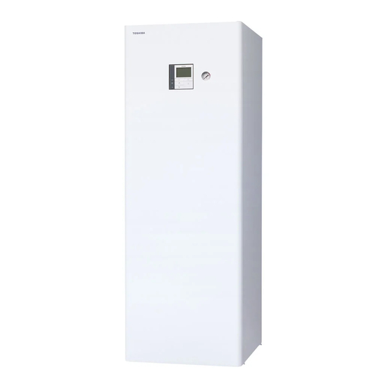
- 7 Main Components of Hydro Unit
- 8 Hydro Unit Installation
- 9 Power Supply
- 10 220-240 V ~ 50 Hz
- 11 Group Control and Optional Controllers
- 12 Start up and Configuration
- 13 Maintenance
- 14 Troubleshooting
- 15 Technical Parameters
- Download this manual
Advertisement
Table of Contents


Need help?
Do you have a question about the HWT-601F21SM3W-E and is the answer not in the manual?
Questions and answers