Table of Contents
Advertisement
Advertisement
Table of Contents
Troubleshooting

Summary of Contents for EPG LevelMaster CHS Series
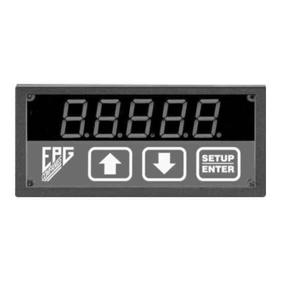
- Page 1 CHS Series LevelMaster™ Level Meter Operations & Configuration Manual For Models: CHS1000 CHS1100 CHS1200 EPG Companies Inc. 19900 County Road 81 Maple Grove, MN 55311 800-443-7426 * www.epgco.com Tech Support * 800-762-8418 © 2018 EPG Companies Inc. Bulletin 3594...
- Page 2 Replacement Guide INTRODUCTION The feature-rich CHS Series Indicating controller is the heart of the EPG Level Master System. The level is determined by detecting changes in hydrostatic pressure using a submerged stainless steel pressure transducer. The EPG Level Indicating Controller ‘reads’ the corresponding analog current and uses one or two of the three internal relays to turn on and off pumps.
- Page 3 Use terminals 13(+) and 14(-) for sourcing inputs (i.e. 4 wire transmitters) For RS-485 or for quick turn-around RS-232, jumper RTS and CTS. For external modem use, connect RTS and CTS to the modem. The modem provides the CTS delays as needed. © 2018 EPG Companies Inc. Bulletin 3594...
-
Page 4: Run Mode
LED segments. It will then display the current input value. If there is no input and the meter was setup at EPG, (EPG standard configuration is for a 0-5PSIG input with 4-20mA output) the meter will display –34.6. In order to change any set points or internal values, one must enter the respective SETUP MODE as defined in the Configuration Guide on page 10 of this manual. -
Page 5: Meter Type
Open or Normally Closed (see 3.4 & 3.5 below). 3.1 20mA CALIBRATION The meter is delivered from EPG pre-calibrated. Under normal operation this setting should NEVER be adjusted. If re-calibration is required consult your EPG representative. 3.2 MODBUS ADDRESS (Addr = 1- 240) Use the UP/DOWN arrow keys to enter the desired Modbus address and press the SETUP/ENTER key. - Page 6 Use the UP/DOWN arrow keys to set a lower alarm limit for a single pump system. 4.5b AlHi2 / AlHi Use the UP/DOWN arrow keys to adjust the Hi/Hi or Hi Alarm for single or dual pump systems. 4.6 HyLo or HyHi (Same as 4.4a above) © 2018 EPG Companies Inc. Bulletin 3594...
-
Page 7: Decimal Point
Pressing the UP/ DOWN arrows simultaneously will cause the meter to display its current configuration and alarm type. Confirm power to all devices and equipment Check configuration of meter (including decimal point location) © 2018 EPG Companies Inc. Bulletin 3594... - Page 8 NOTE: The periodic status message showing “P” indicating the level is such that the pump would normally be required to run will continue to flash despite an active Lockout that prevents the pump relay from actually energizing. © 2018 EPG Companies Inc. Bulletin 3594...
-
Page 9: Modbus Address
7.2 DETAILS The AIH (40003) register contains the scaled analog level as displayed on the meter. Note that the decimal point is implied as this is an integer register. The DIREGo (40001) contains: © 2018 EPG Companies Inc. Bulletin 3594... - Page 10 © 2018 EPG Companies Inc. Bulletin 3594...
- Page 11 Relay 2 (K2) turns off when display drops ________ below R2 HYHi ______ Level ALHi2 ______ Relay 3 (K3) turns on when meter displays = ________ Relay 3 (K3) turns off when display drops ________ below R3 HYHi2 ______ Level © 2018 EPG Companies Inc. Bulletin 3594...
- Page 12 © 2018 EPG Companies Inc. Bulletin 3594...
- Page 13 CHS Series LevelMaster™ Meter Replacement Guide For Models: CHS1000 CHS1100 CHS1200 EPG Companies Inc. 19900 County Road 81 Maple Grove, MN 55311 800-443-7426 * www.epgco.com Tech Support * 800-762-8418 © 2018 EPG Companies Inc. Bulletin 3594...
-
Page 14: Wiring Instructions
13. Move wire from old connector J1 terminal #M to new meter connector J1 terminal #12. Important - Be aware of terminal block orientation when making connections as the terminal blocks may be reverse entry. © 2018 EPG Companies Inc. Bulletin 3594... - Page 15 19. Move one wire from old connector J2 terminal #9 (or #8) to new meter connector J1 terminal #10. Contact EPG Companies if more than two terminals are used on a meter relay output or if there are any remaining wires on the old meter connectors.
-
Page 16: Troubleshooting
Check the loop and fix any Display = -34.6 (level) the 4—20mA loop. problem Confirm meter calibration Meter could be calibrated parameters to make sure they Display = incorrect value wrong. match the pressure (level) sensor. © 2018 EPG Companies Inc. Bulletin 3594... -
Page 17: Meter Settings
Relay 2 (K2) turns off when display drops ________ below R2 Level ALHi2 ______ Relay 3 (K3) turns on when meter displays = ________ HYHi2 ______ Relay 3 (K3) turns off when display drops ________ below R3 Level © 2018 EPG Companies Inc. Bulletin 3594... - Page 18 OLD STYLE I.S. BARRIER © 2018 EPG Companies Inc. Bulletin 3594...
- Page 19 NEW STYLE I.S. BARRIER © 2018 EPG Companies Inc. Bulletin 3594...
- Page 20 EPG Companies Inc. 19900 County Road 81 Maple Grove, MN 55311 800-443-7426 * www.epgco.com Tech Support * 800-762-8418 © 2018 EPG Companies Inc. Bulletin 3594...
Need help?
Do you have a question about the LevelMaster CHS Series and is the answer not in the manual?
Questions and answers