Table of Contents
Advertisement
Quick Links
Advertisement
Table of Contents

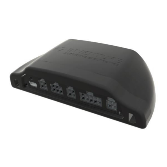
Summary of Contents for Inventure Automotive G2
- Page 1 Reefer Interface G2 based on ™ FMS Gateway G2...
- Page 2 User’s Manual Inventure ™ – FMS Gateway G2 Reefer interface...
- Page 3 All rights reserved. Copyright Notice © Copyright 2020, Inventure, Inc. Revision D01-018-09-04-08-03EN Contact INVENTURE Automotive Electronics R&D, Plc. 11 Tarcali Strret H-1113 Budapest HUNGARY Phone: +36 1 381-0970 E-mail: support@inventure-automotive.com URL: www.inventure-automotive.com © Inventure Automotive Electronics R&D, Plc.
-
Page 4: Table Of Contents
User’s Manual FMS Gateway Table of contents INTRODUCTION ......................5 THE FMS GATEWAY G2 REEFER INTERFACE ............5 ......................5 AIN FEATURES ....................5 DDITIONAL FEATURES FMS G G2 R ....... 6 OW TO USE NVENTURE ATEWAY EEFER NTERFACE SAFETY NOTICES ......................7 PACKAGE CONTENTS .................... -
Page 5: Introduction
Automatic Vehicle Detection which means that after installing the device will detect your vehicle by itself. To use the standard FMS Gateway G2 as Reefer Interface you need to use the General Truck firmware and upload it by using the proper Device Database (the method is detailed in this document) 2.1 Main features... -
Page 6: How To Use Inventure Fms Gateway G2 Reefer Interface
After device installation, please connect input cables (Power, Ground, Vehicle CAN input and other inputs when needed). See Section 5 for more details. o Connect the FMS Gateway G2 output to the input of your AVL device. After successful installation and power-up, the device testing can be started. -
Page 7: Safety Notices
Reefer data beside the GPS position. 3 Safety notices Please read the following safety instructions carefully. Inventure Automotive accepts no liability for damage that results from disregarding the safety instructions. -
Page 8: Package Contents
User’s Manual FMS Gateway 4 Package Contents Please make sure that the package contains the items listed below. FMS Gateway G2 Reefer Interface CL-CAN (contactless CAN) sensor Cable set (optional) User’s Manual (this guide) Installation guide on the specific Reefer model... -
Page 9: Connection Overview
For the device proper functioning, please make sure to connect only to the following points according to the charts. The rest should be left as is (DNC - Do Not Connect). Not used for Reefer Interface Not used for Reefer Interface Not used for Reefer Interface © Inventure Automotive Electronics R&D, Plc. -
Page 10: V_Can 1 Connector
Analog sensor input (e.g.: fuel level sensor) RS232 TXD RS232 channel transmit data line FMS CAN_H FMS CAN bus CAN High line FMS TER 1 FMS CAN bus terminating resistor activation loop 1 Table 3: Micro Fit 10-pin (MAIN) assignment © Inventure Automotive Electronics R&D, Plc. -
Page 11: Usb Mini Connector
Figure 4: USB Mini B to USB A cable Install device driver Install FMS Gateway Support Tool software Activate FMS Gateway Support Tool software using license file (Send the activation request file in e-mail to Inventure Automotive support) © Inventure Automotive Electronics R&D, Plc. -
Page 12: Installation To Vehicle
During installation please consider safety instructions (see Section 3) and follow the instructions below: Make sure that the FMS Gateway G2 Reefer Interface device has the latest firmware installed, and it is appropriately configure for the Reefer model (check firmware version... -
Page 13: Troubleshooting, Led Status
In this working state the device gets power supply (voltage and current OK) and detects the input CAN and/or DIAG communication channels’ messages. In this operating state the device and the GPS device connection are correct, the GPS device sends CAN acknowledges (in case of FMS CAN connection). © Inventure Automotive Electronics R&D, Plc. -
Page 14: V_Can 1 Error
Check FMS CAN connections for reverse polarity (CAN Low ~2,3V, CAN High 2,7V DC) No CAN acknowledge from GPS device: o If there is no acknowledge on FMS CAN bus then FMS Gateway cannot transfer CAN messages to GPS device. © Inventure Automotive Electronics R&D, Plc. -
Page 15: Bootloader State (Usb Connected)
8 Inventure Support information In case of any problem with device installation, firmware upgrade or any questions please contact Inventure Automotive support team (support@inventure-automotive.com). To get the fastest answer please describe the problem as detailed as possible. Please provide the following information in case of any problem: ... -
Page 16: System Characteristics
Storage temperature ºC Operating temperature ºC Humidity FMS CAN output interface Baud rate Kbaud FMS CAN terminating resistor CAN mode Normal CAN 2.0B ID Box parameters Length Width Height Mass Table 5: System characteristics © Inventure Automotive Electronics R&D, Plc. -
Page 17: Warranty
Remember to save your sales receipt in case of you ever need warranty service. Please refer to the serial number of your FMS GATEWAY G2™ in case of any problems. The serial number can be found on a label outside the box. In case of warranty claims contact your local dealer or directly Inventure, Inc. -
Page 18: How To Contact Inventure
Your comments are also welcome under the following address: Inventure Automotive Electronics R&D, Inc. H-1124 Budapest Fürj Street 2. HUNGARY Phone: (+36) 1 381-0970 © Inventure Automotive Electronics R&D, Plc. -
Page 19: List Of Figures
Table 1: Input description ...................... 9 Table 2: Micro Fit 4-pin (V_CAN 1) assignment ..............10 Table 3: Micro Fit 10-pin (MAIN) assignment ................10 Table 5: Device working status .....................13 Table 6: System characteristics ....................16 © Inventure Automotive Electronics R&D, Plc. - Page 20 http://www.inventure-automotive.com...


Need help?
Do you have a question about the G2 and is the answer not in the manual?
Questions and answers