Advertisement
Quick Links
SAFE 4 eco
riese electronic gmbh
Junghansstraße 16
72160 Horb a. N.
Germany
Tel. +49-(0)7451-5501-0
Fax. +49-(0)7451-5501-70
www.automation-safety.de
Einleitung / Introduction
Zielgruppe/
Target audience
Zeichenerklärung/
Explanation of signs
!
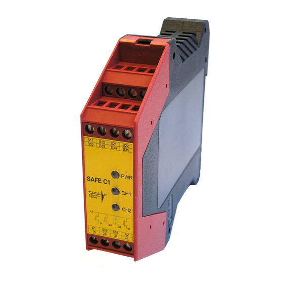
SAFE 4 eco
250313
Abbildung ähnlich
Diese Betriebsanleitung soll Sie mit dem
Not-Halt Sicherheitsrelais und Schutz-
türwächter SAFE 4 eco / 4.1 eco / 4.2
eco / 4.3 eco vertraut machen
Diese Bedienungsanleitung gilt alle Ge-
räte der Serie SAFE 4 eco (siehe „Gerä-
tevarianten"):
Die Betriebsanleitung richtet sich an
folgende Personen:
Qualifizierte Fachkräfte, die Sicher-
heitseinrichtungen für Maschinen
und Anlagen planen und entwickeln
und mit den Vorschriften über Ar-
beitssicherheit und Unfallverhütung
vertraut sind.
Qualifizierte Fachkräfte, die Sicher-
heitseinrichtungen in Maschinen und
Anlagen einbauen und in Betrieb
nehmen.
In dieser Betriebsanleitung werden eini-
ge Symbole verwendet, um wichtige
Informationen hervorzuheben:
Dieses Symbol steht vor Textstellen, die
unbedingt zu beachten sind.
beachtung
führt zur Verletzung von
Personen oder zu Sachschäden.
Dieses Symbol kennzeichnet Textstel-
len, die wichtige Informationen enthal-
ten.
Dieses Zeichen kennzeichnet auszufüh-
rende Tätigkeiten.
Nach diesem Zeichen wird beschrieben,
wie sich der Zustand nach einer ausge-
führten Tätigkeit ändert.
©
Copyright
Alle Rechte vorbehalten. Ände-
rungen, die dem technischen Fortschritt dienen,
vorbehalten.
SAFE 4 eco
SAFE 4.1 eco
SAFE 4.2 eco
SAFE 4.3 eco
Originalbedienungsanleitung
Sicherheitsschaltgeräte für Not-
Halt- und Schutztüranwendungen
Original operating instruction
Safety controller for e-stop and gate
monitoring applications
This operating instruction shall make
you familiar with the emergency stop
and safety gate monitoring relays
SAFE 4 eco /4.1 eco /4.2 eco /4.3 eco
This operation instruction is valid for all
devices of the SAFE 4 eco family (see
"Devices")
The operating instruction is addressed
to the following persons:
Qualified professionals who plan
and develop safety equipment for
machines and plants and who are
familiar with the safety instructions
and safety regulations.
Qualified professionals, who install
safety equipment to machines and
plants and put them into operation.
This operating instruction contains
several symbols which are used to
highlight important information:
This symbol is placed to indicate parts
Nicht-
of text which has to be absolutely paid
attention to. Nonobservance leads to
serious injuries or damage to property.
This symbol is placed to indicate parts
of text, which contains important infor-
mation.
This sign is placed to indicate activities
After this sign follows a description on
how the situation has changed after an
activity is performed.
©
Copyright All
which serve technical improvements are re-
served
rights reserved. Changes,
1 / 21
Advertisement

Summary of Contents for RIESE SAFE 4 eco
- Page 1 This operating instruction shall make Not-Halt Sicherheitsrelais und Schutz- you familiar with the emergency stop türwächter SAFE 4 eco / 4.1 eco / 4.2 and safety gate monitoring relays eco / 4.3 eco vertraut machen SAFE 4 eco /4.1 eco /4.2 eco /4.3 eco...
-
Page 2: Safety Indications
Die Sicherheitsrelais The safety relay SAFE 4 eco / 4.1 eco Verwendung / SAFE 4 eco / 4.1 eco / 4.2 eco / 4.3 eco / 4.2 eco / 4.3 eco is intended to be Intended use sind bestimmt für den Einsatz in:... - Page 3 SAFE 4 eco und induktiven Lasten an den Aus- with capacitive and inductive gangskontakten. loads. In regelmäßigen Zeitabständen The emergency stop relay has to muss das Sicherheitsrelais ausge- be tested in a time interval of every löst werden und auf korrekte Funkti- six months or after each check of on geprüft werden (mindestens je-...
-
Page 4: Montage Und Inbetriebnahme
SAFE 4 eco Montage und Inbetriebnahme Mounting and commissioning Mechanische Für eine sichere Funktion muss das The unit must be panel mounted in an Montage mechanical Sicherheitsrelais in ein staub- und enclosure protected against dust and mounting feuchtigkeitsgeschütztes Gehäuse ein- humidity rated at IP 54 or better. - Page 5 SAFE 4 eco Elektrischer Anschluss Electrical Wiring Anschluss Spannungsversor- Wiring of the power supply gung Beachten Sie hierzu die Angabe auf Please refer to the information on dem Typenschild des Geräts the nameplate of the device Alle 24V Varianten (AC und DC):...
- Page 6 SAFE 4 eco SAFE 4.2 eco: SAFE 4.2 eco: Start SAFE 4.3 eco: SAFE 4.3 eco: Start mit Überwachung des Starttasters; Start (Reset) with monitoring of the das Gerät reagiert auf Öffnen des Tas- start button. The device will be acti- ters (mit dem Schließen der Freigabe-...
- Page 7 SAFE 4 eco Beispiel für die Überwachung einer Kontakterweiterung in den Startkreis SAFE 4 eco: SAFE 4 eco: Start Start mit Überwachung des Starttasters; Start (Reset) with monitoring of the das Gerät reagiert auf Öffnen des Tas- start button. The device will be acti- K1ext terkontakts (Schließen der Freigabe-...
-
Page 8: Wartung Und Reparatur
Do not attempt to repair the unit your- durch. Sollte sich das Gerät als defekt self. In case of failure or malfunction of herausstellen, schicken Sie das Gerät the device send it back to riese elec- an riese electronic gmbh ein. tronic gmbh. Erdschluss bei AC-DC- Die Sicherung löst aus, die Freigabe-... - Page 9 Malfunction of the contacts neue Aktivierung möglich. new activation after the safety circuits → In diesem Fall das Gerät an riese have been opened. electronic einschicken. → In this case please send the device back to riese electronic gmbh.
-
Page 10: Technische Daten / Technical Data
Technische Daten / Technical Data Allgemeine Daten / General Data Gerätetyp / Type of device SAFE 4 eco, SAFE 4.1 eco, SAFE 4.2 eco, SAFE 4.3 eco Elektrische Daten / Electrical data Versorgungsspannung Uv / supply voltage 24V AC/DC Bemesssungsbetriebsspg / rated operational voltage 230V AC / 115V AC. - Page 11 =1800 Zyklus/cycle Gesamt/Total : 7,35·10 mit/with B =400.000, h =24, d =365, t =600 Zyklus/cycle Gesamt/Total: 7,41·10 mit/with B =400.000, h =24, d =365, t Zyklus/cycle SFF > 99% HFT = 1 SIL3 SAFE 4 eco 11 / 19 130110...
- Page 12 Dual channel e-stop monitoring Überwachung mit Querschluss- with cross circuit monitoring sicherheit und überwachtem and monitored start button Start SAFE 4 eco: SAFE 4 eco: Start Mit dem Öffnen des Starttastenkon- After the start button contacts takts schließen die Freigabestrom- open the safety circuits close.
- Page 13 überwachtem toring and monitored start but- Start. Start SAFE 4 eco SAFE 4 eco Mit dem Öffnen des Starttastenkon- After the start button contacts takts schließen die Freigabestrom- open the safety circuits close.
- Page 14 Kontakterweiterung“). Hint: This start type is not valid Hinweis: Diese Startart ist für Not- for e-stop applications. halt-Anwendungen nicht zugelas- sen. Max. achievable: cat. 4, SIL3, PLe Max. erreichbar: Kat. 4, SIL3, PLe SAFE 4 eco 14 / 19 130110...
- Page 15 Einkanalige Nothalt- und Schutz- Single channel e-stop and tür-Überwachung mit überwach- safety gate monitoring with tem Start monitored start button SAFE 4 eco SAFE 4 eco Start Die Freigabestromkreise schließen The safety circuits close if trigger bei geschlossenem Auslöseele- element contact is closed and the mentkontakt und dem Schließen...
- Page 16 Max. erreichbar: Kat. 4, SIL3, PLd when using restricted guided switches and (Diese Kennwerte sind nur erreichbar bei the wiring is lead in separated coated Verwendung von zwangstrennenden Schal- cables.) tern und Verlegung der Kabel in getrennten Mantelleitungen!) SAFE 4 eco 16 / 19 130110...
- Page 17 A1 A2 Die Freigabestromkreise schließen The safety circuits close after the mit dem Schließen des Schutztür- start button is opened. Kontaktes. Max. achievable: cat. 4, SIL3, PLe Max. erreichbar: Kat. 4, SIL3, PLe SAFE 4 eco 17 / 19 130110...
- Page 18 The loopback contacts of the SAFE Die Rückführkontakte des SAFE X4 X4 (Y1-Y2) are looped into the start (Y1-Y2) werden in den Startkreis des circuit of the SAFE 4 eco (all vari- SAFE 4 eco (alle Varianten) einge- ants). schleift.
- Page 19 Gerätevarianten / Devices Name / Name: Spannung / Voltage: Artikel-Nummer. / Article number: SAFE 4 eco 24 V AC/DC AA.9675.2000 SAFE 4 eco 115 V AC AA.9675.4000 SAFE 4 eco 230 V AC AA.9675.5000 SAFE 4.1 eco 24 V AC/DC AR.9678.2000...
- Page 20 Ihr Kontakt zu riese electronic / your contact to riese electronic: Weitere Länder- / Gebiets – Vertretungen finden Sie auch im Internet: all our representations can be found on our homepage: www.automation-safety.de/deutsch/index.htm www.automation-safety.com/englisch/index.htm Deutschland Stammhaus: / Head office Junghansstr. 16...
Need help?
Do you have a question about the SAFE 4 eco and is the answer not in the manual?
Questions and answers