
Related Manuals for Imagine Platinum Predator II-GX 2RU


Summary of Contents for Imagine Platinum Predator II-GX 2RU
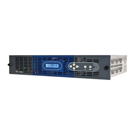
- Page 1 Installation and Operation Manual Platinum™ Predator II-GX 2RU Expandable Multiviewers Series Edition E 175-100253-00...
- Page 2 Imagine Communications reserves the right, without notice to make such changes in equipment, design, specifications, components, or documentation as progress may warrant to improve the performance of the product.
-
Page 3: Table Of Contents
Installation ......................22 Unpacking a Predator II GX Frame ......................22 Preparing the Product for Installation....................22 Checking the Packing List ........................22 Installation Guidance and Safety ......................23 © 2014 Imagine Communications. Proprietary and Confidential. Edition E | Page 3... - Page 4 Using ZConfigurator to Assign an IP Address ..................45 Changing Network Settings ........................ 46 Troubleshooting Failed Connections ....................47 Using Control View ..........................48 Using the PiP Source Selector ......................48 © 2014 Imagine Communications. Proprietary and Confidential. Edition E | Page 4...
- Page 5 Navigating the menu ..........................89 Example Menu Operations ........................91 Selecting Presets ..........................91 Full Screen ............................91 Changing Output Resolution ......................91 Changing Display Mode ........................91 © 2014 Imagine Communications. Proprietary and Confidential. Edition E | Page 5...
- Page 6 Audio IPs ............................106 Communication Ports ........................108 DVI Connector ..........................108 Audio Monitoring and Master GPI I/O ..................... 110 External Time Code .......................... 110 Index ........................111 © 2014 Imagine Communications. Proprietary and Confidential. Edition E | Page 6...
-
Page 7: Preface
Writing Conventions Term or Convention Description Bold Indicates dialog boxes, property sheets, fields, buttons, check boxes, list boxes, combo boxes, menus, submenus, windows, lists, and selection names © 2014 Imagine Communications. Proprietary and Confidential. Edition E | Page 7... -
Page 8: Obtaining Documents
Except for firmware upgrades, Predator II modules are not designed for field servicing. All hardware upgrades, modifications, or repairs require you to return the modules to the Customer Service center. © 2014 Imagine Communications. Proprietary and Confidential. Edition E | Page 8... -
Page 9: Returning A Product
Statements identifying conditions or practices that may result in personal injury or loss of life. High voltage is present. CAUTION Statements identifying conditions or practices that can result in damage to the equipment or other property. © 2014 Imagine Communications. Proprietary and Confidential. Edition E | Page 9... -
Page 10: Waste From Electrical And Electronic Equipment (Weee) Directive
July 1, 2006, and it refers to the following hazardous substances: Lead (Pb) Mercury (Hg) Cadmium (Cd) Hexavalent Chromium (Cr-V1) Polybrominated Biphenyls (PBB) Polybrominated Diphenyl Ethers (PBDE) © 2014 Imagine Communications. Proprietary and Confidential. Edition E | Page 10... - Page 11 July 1, 2006 are exempt from the legislation. Equipment that complies with the EU directive are marked with a RoHS-compliant emblem, as shown below. Figure 2: ROHS Compliance Symbol © 2014 Imagine Communications. Proprietary and Confidential. Edition E | Page 11...
-
Page 12: Introduction
Applications (on page 15) Signal Flow and Rear I/O (on page 15) Introducing ZConfigurator for Predator II GX (on page 16) Ordering Codes (on page 20) © 2014 Imagine Communications. Proprietary and Confidential. Edition E | Page 12... -
Page 13: Main Features
UMD (Under Monitor Display) and tally control interface with support for Zandar, Thomson Ascii, Probel, TSL,Imagine Communications (LRC), Ross and Image Video native protocols Support for re-mapping Imagine Communications Platinum and Ross switcher source assignments (new) On-screen clocks and timers with support for NTP (Network Time Protocol) time code ... -
Page 14: Example Dvi-I Outputs
A built-in dual head facility allows any input to be shown on any output and two displays can be driven as a single virtual display so that a single layout spans two horizontal displays. © 2014 Imagine Communications. Proprietary and Confidential. -
Page 15: Applications
Broadcast monitoring in studios, production control rooms, master control rooms, and OB trucks Command and Control Room monitoring Satellite center and cable head-end monitoring Signal Flow and Rear I/O Figure 6: Predator II GX 2RU signal flow © 2014 Imagine Communications. Proprietary and Confidential. Edition E | Page 15... -
Page 16: Introducing Zconfigurator For Predator Ii Gx
PC that is connected to one or more multiviewers using the Ethernet connector on the rear of the frame. In addition, ZConfigurator provides signal monitoring, alarm feedback, and layout creation and design capabilities. © 2014 Imagine Communications. Proprietary and Confidential. Edition E | Page 16... -
Page 17: Presets
To select a preset for display and activate it simply click on its layout icon. To view brief details of the desired preset, hover the mouse over its icon. © 2014 Imagine Communications. Proprietary and Confidential. Edition E | Page 17... -
Page 18: Control View
In the example above, a PiP1 control window is open, ready to accept a double-click of the mouse to send it full screen on the attached multiviewer. © 2014 Imagine Communications. Proprietary and Confidential. Edition E | Page 18... -
Page 19: The Layout Editor
Other PiP elements that can be added include labels, UMDs, tallies, borders, timers, and alarms. For more information, press F1 while you are using ZConfigurator to open the online help, or see Using ZConfigurator (on page 38). © 2014 Imagine Communications. Proprietary and Confidential. Edition E | Page 19... -
Page 20: User Configurable Network Control Panels
User Configurable Network Control Panels The Predator II series are supported by the rack mount and desktop Nucleus remote panels. They can be programmed to support any CSS compatible Imagine Communications product. Both panels will be able to support applicable features from the following: Full screen recall ... - Page 21 2RU Programmable Panel - for Full screen recall, Layout recall, Audio monitor output selection, Timer start/stop/reset NUCLEUS-MV-DM Desktop Programmable Panel - for Full screen recall, Layout recall, Audio monitor output selection, Timer start/stop/reset © 2014 Imagine Communications. Proprietary and Confidential. Edition E | Page 21...
-
Page 22: Installation
• One Predator II GX frame with modules and rear versions) connectors fitted according to order. • One Predator II GX Installation and Operation Manual • One ZConfigurator for Predator II GX CD © 2014 Imagine Communications. Proprietary and Confidential. Edition E | Page 22... -
Page 23: Installation Guidance And Safety
Mounting of the equipment in the rack should be such that a hazardous Mounting condition is not achieved due to uneven mechanical loading. See Installing the Predator II GX Frame (on page 24). © 2014 Imagine Communications. Proprietary and Confidential. Edition E | Page 23... -
Page 24: Installing The Predator Ii Gx Frame
When you connect sources to DVI inputs or DVI outputs to one or more displays, observe the following: Do not use a DVI cable that is greater than 10 m long. Consider using a powered extender when longer cable lengths are required. © 2014 Imagine Communications. Proprietary and Confidential. Edition E | Page 24... -
Page 25: Video Input Cables
Accept default locations for the installation directory or enter preferred locations. The controlling PC will need to be configured when connecting to a multiviewer for the first time. Refer to Using ZConfigurator (on page 38) for more information. © 2014 Imagine Communications. Proprietary and Confidential. Edition E | Page 25... -
Page 26: User Upgrade
I/O plates for the VID4 kit carry four mounting screw holes with the generic text 'IN' under each BNC through hole. I/O plates for the DVI kit carry fourmounting screw holes with the generic text ‘DVI IN’ under each DVI-I connector aperture. © 2014 Imagine Communications. Proprietary and Confidential. Edition E | Page 26... -
Page 27: Front Loading Module Expansion
Always read the warnings in Installation Guidance and Safety (on page 23) before commencing any hardware upgrade. WARNING Always remove power before inserting or removing cards, or while covers are removed. © 2014 Imagine Communications. Proprietary and Confidential. Edition E | Page 27... -
Page 28: Installing Audio Daughter Cards
Circular, threaded through, nylon M3 pillar FAS-ZAN-034 M3x4 pozi head screw Fitting Instructions If necessary, remove any existing VID4 cards as explained in Removing and Re-Installing Video Cards (on page 30). © 2014 Imagine Communications. Proprietary and Confidential. Edition E | Page 28... - Page 29 Figure 10: Securing an analog audio daughter card in place Alternatively, the nylon pillars may first be secured to the daughter card. The digital daughter card is fitted in exactly the same way as an analog one. © 2014 Imagine Communications. Proprietary and Confidential. Edition E | Page 29...
-
Page 30: Removing And Re-Installing Video Cards
Installing New Front-Loading Cards and Rear Install additional rear I/O in the Predator II GX 2RU frame as follows: 1. Gain access to the rear of the frame and remove the power. © 2014 Imagine Communications. Proprietary and Confidential. Edition E | Page 30... - Page 31 1 and DVI-I cards in high slot numbers starting at slot 8. Slot numbers are silk-screened on both sides of the backplane. © 2014 Imagine Communications. Proprietary and Confidential. Edition E | Page 31...
- Page 32 6. Gain access to the rear of the frame, re-power the unit and test that the new cards and any new I/O function correctly. Predator II GX will auto-detect new cards at power on and configure itself accordingly. © 2014 Imagine Communications. Proprietary and Confidential. Edition E | Page 32...
-
Page 33: Updating Firmware
By default the upgrade will proceed to flash the main on-board software for the CPU, Display Card and any input processor cards such as VID4 and DVI2 cards. © 2014 Imagine Communications. Proprietary and Confidential. Edition E | Page 33... - Page 34 Leave the card slot selection unchecked to have Z_Upgrade search for and upgrade all applicable input cards. 7. For each input card, use the VID4 and DVI2 tabs to select the specific files to update. © 2014 Imagine Communications. Proprietary and Confidential. Edition E | Page 34...
- Page 35 Chapter 3 Installation and Operation Manual User Upgrade The VID4 file settings should be left at default values unless otherwise instructed by Imagine Communications Customer Services. The DVI2 file settings should be left at default values unless otherwise instructed by Imagine Communications Customer Services.
- Page 36 11. If necessary, double click on an entry row to see error details. Z_Upgrade and the multiviewer front panel(s) should display a message asking for the unit(s) to be power cycled. Pls power cycle this unit © 2014 Imagine Communications. Proprietary and Confidential. Edition E | Page 36...
-
Page 37: Z_Update Faq
Check with Customer Services that you have the appropriate version of ZConfigurator required to support any new features and that any required license(s) are in place. © 2014 Imagine Communications. Proprietary and Confidential. Edition E | Page 37... -
Page 38: Using Zconfigurator
However, video sources have a much wider range of possible settings which include Audio Bar Graphs, Tallies, Comprehensive Alarms, Border size and color, Safe Area and Aspect Ratio Markers and both VITC and Closed Captions. © 2014 Imagine Communications. Proprietary and Confidential. Edition E | Page 38... - Page 39 To have ZConfigurator adjust the aspect ratio of the PiP automatically, check the Auto-Detect box under Aspect Ratio Management. Position Adjustment, Frequency and Phase The settings on the Position Adjustment tab are for analog RGB signals only and do not affect digital signals. © 2014 Imagine Communications. Proprietary and Confidential. Edition E | Page 39...
-
Page 40: Using The Stand Alone Text Box
Check available test signals with the supplier of the source equipment, or in the case of a PC use proprietary test signal software. If another Imagine Communications multiviewer is available, use its in-built test signals (i.e. from the ZConfigurator System Properties >> Display tab of another Predator II GX/GRF). - Page 41 3. Click on the Text Color box and select a suitable text color from the standard multiviewer color range tool. 4. On the Size Items tab, select a text panel size from a choice of Small, Normal or Large. © 2014 Imagine Communications. Proprietary and Confidential. Edition E | Page 41...
-
Page 42: Status Panel Over Video
Also, if the monitoring audio level is changed in Control View, the change can be saved to the current layout. See Audio Monitoring (on page 50) and Controlling Level (on page 52). © 2014 Imagine Communications. Proprietary and Confidential. Edition E | Page 42... -
Page 43: Using The X-Y Re-Mapping Tool
Setup (on page 63). Quick Video Source Selection Control View allows the video source assigned to a PiP to be changed on the fly if a Imagine Communications Platinum router has been attached and configured to use the Imagine Communications LRC protocol. - Page 44 1. Access System Configuration >> Config Network >> Edit IP Address and enter a unique address for your network. 2. Launch ZConfigurator (Start > Programs > ZConfigurator.) and double-click on the Predator II GX connection icon (or right click and select Connect) © 2014 Imagine Communications. Proprietary and Confidential. Edition E | Page 44...
-
Page 45: Using Zconfigurator To Assign An Ip Address
3. Then access System Information >> IP address and make a note of the address. Alternatively, make a note of the IP address shown on an attached display monitor during power-up. To continue the first time connection procedure: © 2014 Imagine Communications. Proprietary and Confidential. Edition E | Page 45... -
Page 46: Changing Network Settings
3. If required, enable and enter a gateway address. 4. Click OK to apply when done. 5. Return the PC to its normal network address. See Troubleshooting (on page 101) for help if required. © 2014 Imagine Communications. Proprietary and Confidential. Edition E | Page 46... -
Page 47: Troubleshooting Failed Connections
The name field and TCP port field (normally 4001) are not used in this connect form. See also answers to "ZConfigurator cannot access any Multiviewers on the network" in Frequently Asked Questions (on page 102). © 2014 Imagine Communications. Proprietary and Confidential. Edition E | Page 47... -
Page 48: Using Control View
Control View can be used to take any selected PiP Full Screen, and for multiviewers equipped with an Audio Monitor Output, to monitor any pair of audio channels. If an Imagine Communications Platinum router is connected, Control View can also provide access to a Source Selector for each PiP. -
Page 49: Full Screen
PiP and the word Full will appear just below the cursor which changes to show a '+' sign). To take this PiP full screen on the attached display immediately, double-click with the cursor at the current position. © 2014 Imagine Communications. Proprietary and Confidential. Edition E | Page 49... -
Page 50: Audio Monitoring
To control which audio channels in a PiP are monitored: 1. Click once on the appropriate PiP. The selected PiP will zoom out with the rest hatched out. © 2014 Imagine Communications. Proprietary and Confidential. Edition E | Page 50... - Page 51 When the layout is restored, the previous monitored audio channel assignment will also be restored. No change occurs if the PiP taken fullscreen has no assigned audio. © 2014 Imagine Communications. Proprietary and Confidential. Edition E | Page 51...
-
Page 52: Controlling Level
Click on Yes to store the level and/or monitoring changes in the current layout and download the layout. If confirmed, the active layout containing any changes will be sent to the multiviewer. © 2014 Imagine Communications. Proprietary and Confidential. Edition E | Page 52... -
Page 53: Introduction To The Layout Editor
(camera or computer) from the Sources tab. Video sources can be duplicated enabling two PiPs to have the same source (but, say, different audio) while a single primary computer source can only be assigned to one PiP. © 2014 Imagine Communications. Proprietary and Confidential. Edition E | Page 53... -
Page 54: Themes
The following illustration shows some of the panels, panel objects, video objects and PiP elements that are used in a PiP. The most basic component of a PiP Container is the Main Panel. It is the panel to which all other panels dock. © 2014 Imagine Communications. Proprietary and Confidential. Edition E | Page 54... -
Page 55: Adding Audio Panels
To add audio panels to a PiP’s video, right click on it’s video icon and select Add Audio Left or Add Audio Right. To zoom into or enlarge a PiP shown in a layout, double-click on the PiP. © 2014 Imagine Communications. Proprietary and Confidential. Edition E | Page 55... - Page 56 Assigning Audio Source Monitoring to Audio Panels Once one or more left and/or right Audio Panels have been inserted, right click one, select Audio Setup and map audio channels as required. © 2014 Imagine Communications. Proprietary and Confidential. Edition E | Page 56...
-
Page 57: Configuring Predator Ii Gx Settings
Configuration steps include selecting a LAN or serial port to accept the source name data and setting a protocol to decode it. Refer to UMD and Tally Configuration (on page 61) and Communication Ports (on page 65) for more information. © 2014 Imagine Communications. Proprietary and Confidential. Edition E | Page 57... -
Page 58: Complete Configuration
Copying Settings to Other Units (on page 84) Setting Master GPI Output Options (on page 85) Using Bitmap Images (on page 86) Changing System Themes (on page 87) © 2014 Imagine Communications. Proprietary and Confidential. Edition E | Page 58... -
Page 59: Configuring Dvi Output And Resolution
6. Using test patterns: To select a test pattern, select it from the drop-down list. See Using Test Signals (on page 40). 7. Click on OK or Apply when done. Configuring the Display On the ZConfigurator Main Panel, click System Setup. © 2014 Imagine Communications. Proprietary and Confidential. Edition E | Page 59... - Page 60 Select 59.94Hz or 50Hz to match source refresh rate and attached display. Click OK, then click OK on the System Setup dialog box to save changes. © 2014 Imagine Communications. Proprietary and Confidential. Edition E | Page 60...
-
Page 61: Umd And Tally Configuration
1. Open the System Properties dialog box and select the UMD and Tally tab. 2. Select the desired protocol from the Protocol drop down box. Tallies are added as a component to a PIP in the edit layout window. © 2014 Imagine Communications. Proprietary and Confidential. Edition E | Page 61... -
Page 62: Ross Switcher Setup
4. Check Source Trace to allow ZConfigurator to dynamically query source names. 5. Click on OK to save the configuration and dismiss the mapping tool. © 2014 Imagine Communications. Proprietary and Confidential. Edition E | Page 62... -
Page 63: Platinum Router Setup
Platinum Router Setup Use the dedicated Router tab to map sources and destinations for connected LRC routers supported by that tab (currently the Imagine Communications Platinum Router). 1. Check the Enable box to work with a Platinum router and the LRC Protocol. - Page 64 4. Check Display Output Names to show output names from the Platinum router database. 5. Click OK when done. The port number used here is in addition to the tally port configuration described in Communication Ports (on page 65). © 2014 Imagine Communications. Proprietary and Confidential. Edition E | Page 64...
-
Page 65: Communication Ports
Serial COM port services or devices may include: • • Horita RTC (Real Time Clock) • UMD and Tally UMD and Tally are used in the Predator II-GX video system for broadcast production control. © 2014 Imagine Communications. Proprietary and Confidential. Edition E | Page 65... -
Page 66: Gpi Mapping
The default port used to communicate with an external 3rd party UMD and Tally controller over a LAN is 4003. See also the port setup for Imagine Communications Routers that use the LRC protocol in UMD and Tally Configuration (on page 61). - Page 67 For example, if a GPI with Physical ID 1 on slot 1 is assigned to Tally 1 on Source 1, it controls tally 1 for video source 1. Full Screen Closing the GPI contact causes the associated PiP to be displayed full screen. © 2014 Imagine Communications. Proprietary and Confidential. Edition E | Page 67...
-
Page 68: Audio Settings
AES bar/scale. AES Bar Scale Scale Dynamic Range Attack Time Decay Time AES/EBU 45 dB, 0 to -45 dB One sample 1.5 s per 20 dB decay © 2014 Imagine Communications. Proprietary and Confidential. Edition E | Page 68... - Page 69 2. In the Audio Meter Type, select the appropriate option. 3. Set the Yellow/Red Transition point (upper transition point). 4. Set the Green/Yellow Transition point (lower transition point). 5. Click OK. © 2014 Imagine Communications. Proprietary and Confidential. Edition E | Page 69...
-
Page 70: Global Alarm Settings
(Normally used with noisy analog inputs) Black Picture Time in seconds (1-60) - the amount of time a video source would need to remain below the black level threshold before being declared black. © 2014 Imagine Communications. Proprietary and Confidential. Edition E | Page 70... -
Page 71: Enabling Alarms
Enabling video and/or audio alarms for each PiP, including flashing borders, is accomplished within the Layout Editor of ZConfigurator. Alarms are only relevant for PiPs with a video source and/or at least one audio panel with assigned audio sources. © 2014 Imagine Communications. Proprietary and Confidential. Edition E | Page 71... - Page 72 2. To define which video parameters cause alarms click on the Video Alarms tab. 3. Enable the required alarm event triggers. Options that don’t currently apply are grayed out. © 2014 Imagine Communications. Proprietary and Confidential. Edition E | Page 72...
- Page 73 1. Select notification options on the General tab by placing a tick against the required response. 2. To define which audio parameters cause alarms click on a Panel tab. 3. Enable the required alarm event triggers. © 2014 Imagine Communications. Proprietary and Confidential. Edition E | Page 73...
-
Page 74: Time Synchronisation
Horita - clocks are synchronized to LTC using the Horita LTC to Serial option (no longer available) and cannot be used with multiviewers that do not possess a serial port. © 2014 Imagine Communications. Proprietary and Confidential. Edition E | Page 74... -
Page 75: Managing Language Packs And Fonts
The system fonts that an attached Predator II multiviewer uses to display on-screen features can be changed from a choice of fonts installed to the multiviewer. The fonts menu is not available on multiviewers that do not support this feature. © 2014 Imagine Communications. Proprietary and Confidential. Edition E | Page 75... - Page 76 Chapter 4 Installation and Operation Manual Using ZConfigurator In addition, Language Packs can be obtained from Imagine Communications to support different languages and special fonts. Label Fonts To change the font assigned to a particular feature, use the drop down box against each feature to ...
- Page 77 Simplified Chinese and view it in the Layout Editor and use it on-screen. Also refer to the documentation that came with your language pack for any additional help that may be available. © 2014 Imagine Communications. Proprietary and Confidential. Edition E | Page 77...
-
Page 78: Using Snmp Agents
To use an SNMP agent check the Activate SNMP Agent box and enter an appropriate IP address and subnet mask. Community name is a read only information field. © 2014 Imagine Communications. Proprietary and Confidential. Edition E | Page 78... -
Page 79: Checking And Optimizing Installed Cards
If a card is removed (or fails to respond at boot time), ZConfigurator may report an error. Please contact your local service representative for support if this problem occurs. Press OK or Cancel to leave the cards menu, or click on Advanced for other options. © 2014 Imagine Communications. Proprietary and Confidential. Edition E | Page 79... - Page 80 1. Ensure that at least one video signal is connected to each card to be optimized. 2. Select the cards to optimize then click Run Autoskew. The video card optimization procedure may take some time to complete. 3. Click Close when done. © 2014 Imagine Communications. Proprietary and Confidential. Edition E | Page 80...
-
Page 81: Setting System Properties
CPU of the unit itself. The connection name may be changed using ZConfigurator but the serial number and unit type name cannot. © 2014 Imagine Communications. Proprietary and Confidential. Edition E | Page 81... - Page 82 To recall the multiviewer factory settings: 1. Click the Factory Reset button. A message will be shown warning that all layouts currently stored on the multiviewer will be overwritten. © 2014 Imagine Communications. Proprietary and Confidential. Edition E | Page 82...
- Page 83 When the reset is finished the multiviewer should reboot. ZConfigurator will then attempt to reconnect with the multiviewer, provided another connection has not been made. 3. If necessary, re-connect by double clicking on the unit’s connection icon. © 2014 Imagine Communications. Proprietary and Confidential. Edition E | Page 83...
-
Page 84: Copying Settings To Other Units
When Replicating or using Profile Load and Save the target multiviewers should be of the same type as the source. Settings not applicable to the destination unit will be ignored. © 2014 Imagine Communications. Proprietary and Confidential. Edition E | Page 84... -
Page 85: Setting Master Gpi Output Options
Reconnect to the unit after the profile has been loaded to enable the preset list to be updated. Setting Master GPI Output Options Master GPI Output settings can be changed to affect the alarm state condition for the Master GPO. © 2014 Imagine Communications. Proprietary and Confidential. Edition E | Page 85... -
Page 86: Using Bitmap Images
For best results, images should be chosen or pre-sized so that they map directly into a proposed layout without the need for further scaling. Each bitmap must be loaded into a multiviewer before it can be used. © 2014 Imagine Communications. Proprietary and Confidential. Edition E | Page 86... -
Page 87: Changing System Themes
A system theme is a set of on-screen ‘rendering’ styles that affect the look of every PiP element in a layout rendered by a multiviewer. Each multiviewer can support only one active system theme at a time. © 2014 Imagine Communications. Proprietary and Confidential. Edition E | Page 87... - Page 88 System Theme drop down list. Changing the system theme effects all presets on the system.The theme selector in the Layout Editor only changes the theme elements previewed when editing layouts. © 2014 Imagine Communications. Proprietary and Confidential. Edition E | Page 88...
-
Page 89: Using The Front Control Panel
The LCD menus available at the front panel are intended to provide a simplified range of operation and configuration functions to allow standalone Predator II multiviewers to be operated and to allow initial © 2014 Imagine Communications. Proprietary and Confidential. - Page 90 Use the Down arrow to cycle through available menus downwards and the Up arrow to cycle through menus in the upward direction. The Left and Right buttons change parameters or settings. Some menus, such as the System Configuration menu have further submenus. © 2014 Imagine Communications. Proprietary and Confidential. Edition E | Page 90...
-
Page 91: Example Menu Operations
Press MENU to leave the menu and move back up the menu system. Changing Display Mode Navigate to the Display Mode menu in System Configuration. © 2014 Imagine Communications. Proprietary and Confidential. Edition E | Page 91... -
Page 92: Viewing The Multiviewer Ip Address
Press OK to enter the menu. Select Edit IP Address... <> OK IP Address 192.168.1.201 Press OK to enter edit mode. <>^¬ OK IP Address © 2014 Imagine Communications. Proprietary and Confidential. Edition E | Page 92... -
Page 93: Restoring Factory Settings
Press the Left or Right arrow key to change NO to YES. Press OK to start the process. Setting Factory Defaults The boot process will start after default settings are restored. © 2014 Imagine Communications. Proprietary and Confidential. Edition E | Page 93... -
Page 94: Specifications
Specifications and designs are subject to change without notice. Auto-Sensing Video Inputs Video Input Item Auto-Sensing Video I/P Specification Number of video 12, 16, 20, 24, or 32 inputs Type Automatic line and color standard sensing © 2014 Imagine Communications. Proprietary and Confidential. Edition E | Page 94... -
Page 95: Dvi-I Inputs
Connector 2 x Microcross Standards 10 bit DVI-I or RGBHV up to 165MHz Resolution 1024x768, 1280x720 (720p), 1280x768, 1280x1024, 1400x1050, 1360x768, 1680x1050, 1600x1200, 1920x1080, 1920x1200 (single head only) © 2014 Imagine Communications. Proprietary and Confidential. Edition E | Page 95... -
Page 96: Audio
Harlink 10 position, 2 row mating cable receptacle. Note: This connector is shared with Master GPI Impedance 50 Ω To connect to the 10 position Harlink connector use the Harlink breakout cable; order code ZP2-HAR. © 2014 Imagine Communications. Proprietary and Confidential. Edition E | Page 96... -
Page 97: Gpi I/O
Connector Harlink 10 position, 2 row mating cable receptacle LTC Input LTC Input Item Specification Type Unbalanced Connector Input Impedance 75Ω Supported Formats SMPTE 12M, SMPTE 309M, Leitch © 2014 Imagine Communications. Proprietary and Confidential. Edition E | Page 97... -
Page 98: Umd Protocols
Chapter 6 Installation and Operation Manual Specifications UMD Protocols Zandar, Probel, TSL, Ross, Thomson Simple, Image Video, Imagine Communications LRC, Ross Ancillary Data Decode Closed Caption decode and display (EIA 608, 708) D-VITC decode and display (RP188) Source ID (SMPTE 291M) -
Page 99: Housing
Predator II GX Base Model Max. Dissipation ZP2-HD4-GX 69 W ZP2-HD8-GX 91 W ZP2-HD12-GX 116 W ZP2-HD16-GX 138 W ZP2-HD20-GX 160 W ZP2-HD24-GX 187 W ZP2-HD32-GX 236 W © 2014 Imagine Communications. Proprietary and Confidential. Edition E | Page 99... -
Page 100: Environmental
CE Generic Immunity Standard 50082-1:1992 (as per the EMC directive 89/336/EEC) FCC Class A digital device, pursuant to part 15 of the FCC Rules. RoHs Compliant. Compliant with WEEE directive. © 2014 Imagine Communications. Proprietary and Confidential. Edition E | Page 100... -
Page 101: Troubleshooting
I/P lock status can be seen using ZConfigurator on-screen video alarms and it is not normally necessary to view status LEDs on the front edge of installed modules. © 2014 Imagine Communications. Proprietary and Confidential. Edition E | Page 101... -
Page 102: Dvi Two (Computer) Input Card
In addition, some displays require gamma adjustment to achieve full dynamic range. © 2014 Imagine Communications. Proprietary and Confidential. Edition E | Page 102... - Page 103 Predator II GX is. when the Predator II GX is powered on. It can also be found using the Front Control Panel. See Viewing the Multiviewer IP Address (on page 92). © 2014 Imagine Communications. Proprietary and Confidential. Edition E | Page 103...
- Page 104 Cable length for digital signals may be as low as two meters, but it can be use? increased using powered DVI extenders; order code, Z-DVI-EXT. How do I connect to GPI I/O? Use the Harlink GPIO breakout cable; order code, ZP2-HAR. © 2014 Imagine Communications. Proprietary and Confidential. Edition E | Page 104...
-
Page 105: Connectors And Cables
External audio capability depends on additional ‘daughter’ cards that are plugged into each 4-input video card. See User Upgrade (on page 26) for details of audio, video, and DVI-I input expansion. © 2014 Imagine Communications. Proprietary and Confidential. Edition E | Page 105... -
Page 106: Gpi I/O
GPI inputs are active when low (grounded). Audio IPs External audio I/O may be analog or digital depending on frame configuration. Analog Audio Figure 23: Two Harlink sockets labelled Audio for each VID4 card © 2014 Imagine Communications. Proprietary and Confidential. Edition E | Page 106... - Page 107 IN6+ IN2+ yellow IN5- IN1- rose IN5+ IN1- brown Digital audio conforms to AES3, EIAJ CP1201 and IEC-60958 at 48kHz. The digital input impedance is 110 Ohms. © 2014 Imagine Communications. Proprietary and Confidential. Edition E | Page 107...
-
Page 108: Communication Ports
RS-232 port. Custom cabling is required when Com2/3 is programmed to communicate as an RS422/485 port. Pin No Function Pin No Function DVI Connector Figure 26: DVI connector © 2014 Imagine Communications. Proprietary and Confidential. Edition E | Page 108... - Page 109 DDC CLOCK DATA 5+ DDC DATA CLOCK SHIELD CLOCK + DATA 1- CLOCK - DATA 1+ DATA 1/3 SHIELD DATA 3- DATA 3+ +5V POWER DATA GND Analog Ground © 2014 Imagine Communications. Proprietary and Confidential. Edition E | Page 109...
-
Page 110: Audio Monitoring And Master Gpi I/O
System clocks may also be synced to an NTP server or the PC's internal clock. Refer to Time Synchronisation (on page 74) for more information. © 2014 Imagine Communications. Proprietary and Confidential. Edition E | Page 110... -
Page 111: Index
Factory reset • 82 Panels • 54 using control panel • 93 Part numbers • 20 Frame PC clock • 74 installing • 24 Pinouts Front control panel • 89 © 2014 Imagine Communications. Proprietary and Confidential. Edition E | Page 111... - Page 112 • 98 temperature • 100 Synchronization • 74 System information • 81 System properties • 81 System theme • 87 System time • 74 Tally • 54 © 2014 Imagine Communications. Proprietary and Confidential. Edition E | Page 112...
Need help?
Do you have a question about the Platinum Predator II-GX 2RU and is the answer not in the manual?
Questions and answers