
Summary of Contents for General Photonics BPD-002-OEM-400-15
- Page 1 BPD-002-OEM-400-15 OEM Balanced Photodetector Instruction Note August 14, 2020 Document #: GP-IN-BPD-002-OEM-11 Page 1 of 11...
-
Page 2: Table Of Contents
Table of Contents: Section 1. Specifications: .................... 3 Section 2. Overview: ..................... 4 Section 3. Device Description: ................... 5 3.1 General Description.................... 5 Section 4. Device Operation: ..................8 4.1. Getting Started....................8 4.2. Test Fixture ......................9 Section 5. Warranty and Technical Support:............11 Document #: GP-IN-BPD-002-OEM-11 Page 2 of 11... -
Page 3: Section 1. Specifications
Section 1. Specifications: Photodetector Operating Wavelength 1550 ± 50nm Photodetector Type InGaAs PD Responsivity > 0.8mA / mW at 1550nm <0.2 dB Return Loss >45 dB Maximum Input Power 10 mW RF and Monitor Outputs RF Output Bandwidth (3dB) ≥400 MHz Coupling Lower cut-off frequency <1 MHz... -
Page 4: Section 2. Overview
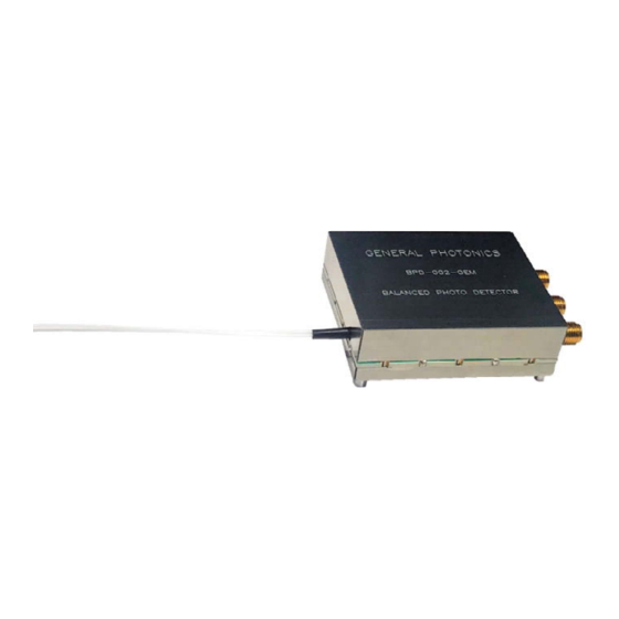
Section 2. Overview: The BPD-002-OEM is a compact, high performance, AC coupled balanced detector specially designed for OEM applications. It has 3 SMA connectors for the RF output and two power monitors. The balanced detectors, monitors, and amplifier circuits are packaged in a compact shielding box with metal standoffs for mounting. -
Page 5: Section 3. Device Description
Section 3. Device Description: 3.1 General Description The BPD-002-OEM is a compact module packaged in a shielding box. Physical and electrical features are described below. 3.1.1 Dimensions Dimensions are shown in Figure 2. Unit: inch Figure 2 Package dimensions (in inches) The BPD can be mounted by using 2-56 screws to connect to the 4 metal standoffs on the bottom of the shielding box. - Page 6 RF output Monitor 2 Monitor 1 Input pigtails Pin 6 Pin 1 Pin 7 Pin 12 Figure 3 BPD-002-OEM with electrical and optical interfaces labeled Optical interface: Input 1 and Input 2 pigtails. Pigtails are labeled. Electrical interfaces: Outputs: RF signal: SMA connector (50Ω) Monitor 1: SMA connector (200Ω) Monitor 2: SMA connector (200Ω) Monitor 2...
- Page 7 Pin 7 Pin 12 Pin 6 Pin 1 Figure 5 Bottom view of BPD-002-OEM Power connector pinout: Pin # Description −5V −5V Document #: GP-IN-BPD-002-OEM-11 Page 7 of 11...
-
Page 8: Section 4. Device Operation
Section 4. Device Operation: Electrical and optical connections are required during setup of the BPD-002-OEM. Follow safety precautions when making these connections. 4.1. Getting Started Unpacking Be careful when unpacking the BPD from its original packaging. Avoid applying any force to optical fiber pigtails, and do not let any free-drop of fiber connectors occur at any time. -
Page 9: Test Fixture
4.2. Test Fixture General Photonics provides a test fixture and cables to facilitate power connections to the BPD-002-OEM for testing. Mating connectors to the BPD-002-OEM’s power connectors, used to mount BPD-002-OEM to the test board. Connectors for cables to connect to power supply... - Page 10 Power cables Monitor 1 RF Out Monitor 2 Optical inputs Figure 7 Test fixture with BPD-002-OEM 3. Verify power supply settings and connect the cables to the ±5V power supplies and to ground. 4. Connect RF output connector (SMA, 50Ω impedance). 5.
-
Page 11: Section 5. Warranty And Technical Support
If the product is found to require factory repair, General Photonics will issue an RMA number for the return. Please label the product clearly with the RMA number.
Need help?
Do you have a question about the BPD-002-OEM-400-15 and is the answer not in the manual?
Questions and answers