Table of Contents
Advertisement
Quick Links
T
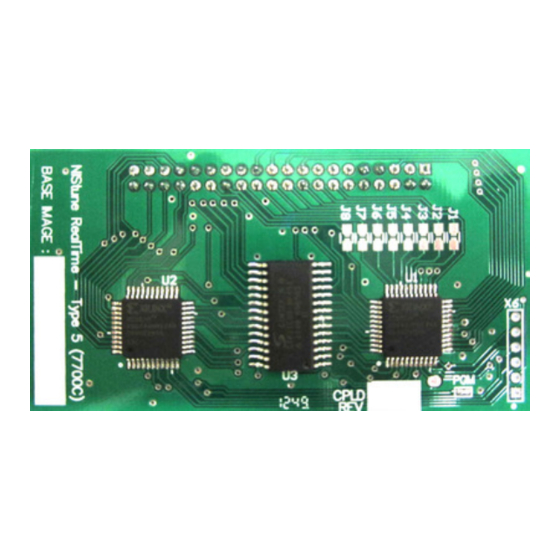
Hardware Installation – Nistune Type 5 boards
Model
Name
S14
Silvia
K11
Micra
B14
Sentra
N14
Pulsar
Z10
Cube
YPE
Version 1.0
Engine
SR20DE
CG10DE/CG13DE
GA16DE
GA16DE
CG13DE
Copyright 2013 Nistune Developments
#5
ECU Series
65F00 (MT only)
0U0xx, 44Bxx, 71Bxx, 72Bxx, 74Bxx, 99Bxx
0M2xx
65Cxx
N/A Contact Nistune
Advertisement
Table of Contents

Summary of Contents for Nistune Type 5
- Page 1 Hardware Installation – Nistune Type 5 boards Version 1.0 Model Name Engine ECU Series Silvia SR20DE 65F00 (MT only) Micra CG10DE/CG13DE 0U0xx, 44Bxx, 71Bxx, 72Bxx, 74Bxx, 99Bxx Sentra GA16DE 0M2xx Pulsar GA16DE 65Cxx Cube CG13DE N/A Contact Nistune Copyright 2013 Nistune Developments...
- Page 2 • There is no need for wiring loom modifications. Nistune provides realtime tuning and maptracing. It provides the ability to make changes on the fly to the factory ECU and then the desired results are achieved, save these permanently in non-volatile memory on the programmable board.
-
Page 3: Table Of Contents
S14 SR20DE Silvia / N15 GA16DE Pulsar / B14 Sentra GA16DE ECU ............ 9 • N14 GA16DE Pulsar ECU .......................... 10 • 4. FIT BOARD TO ECU ............................11 5. FIT PACKING ..............................11 Revision History ..............................12 Type 5 Hardware Installation Manual Page 2 of 15... -
Page 4: Fitting Header To Ecu
Some Bosch ECUs will use star shaped screws which will require the appropriate tool such as pictured in order to remove the screws. These screw drivers are available in specialist electronics shops. Type 5 Hardware Installation Manual Page 3 of 15... -
Page 5: Remove Conformal Coating From Areas To Be Soldered
Jumpers which are to be cleaned are marked R10-R17 and R20-R27. Note that this only applies to some ECUs (see later in the document for details on the jumpers you will be moving). Type 5 Hardware Installation Manual Page 4 of 15... -
Page 6: Remove Solder From The Pads
Hold the ECU up to the light and check that all the holes are clear. If any holes still have solder in them do not try to clear them out using a drill bit! The boards are multi-layer and it is quite likely that an internal connection will be damaged. Type 5 Hardware Installation Manual Page 5 of 15... -
Page 7: Fit The 20+20 Header
• Fit the 20+20 header Clean off flux with acetone or similar solvent. Inspect solder joints. Type 5 Hardware Installation Manual Page 6 of 15... -
Page 8: Change Ecu Jumper Settings
Jumpers are used on the ECU to tell the microcontroller to read from either factory code (located in a memory chip on the ECU main board) or from the Nistune daughterboard. You will need to move the jumper on the ECU so that it will read from the Nistune board The easiest way to move the jumper is to melt the solder on both ends at once by using the de- soldering iron one end and soldering iron the other. -
Page 9: K11 Micra Cg10/Cg13 Ecu
Notes: R20 = 102, R21 = 000, R22 = Open, R23 = Open, R24 = 102, R25 = 301, R26 = 000, R27 = Open Note that the Type 5 board requires all resistor positions R1-R8 on the board to be connected using solder (blob each position) -
Page 10: S14 Sr20De Silvia / N15 Ga16De Pulsar / B14 Sentra Ga16De Ecu
Move jumper R041 to R040 Remove jumper R700 Move resistors R010 - R017 from ECU to J1-J8 on the Nistune Type 5 board using a soldering iron and tweezers. Make sure both ends are soldered when putting on the Nistune board. Use flux to assist solder flow with the SMD resistors. -
Page 11: N14 Ga16De Pulsar Ecu
• N14 GA16DE Pulsar/Sunny, B13 GA16DE Sentra ECU Move jumpers J023 to J020 and J022 to J021 Top side of the ECU move SMD resistors from R011 - R016 to J1 - J8 on the Nistune Type 5 board N14 GA16DE... -
Page 12: Fit Board To Ecu
This is best done by sitting the rubber strip (sticky side up) on top of the Simtek chip which is in the middle of the board, and then carefully fitting the lid. Congratulations – you now have a fully tuneable ECU! Type 5 Hardware Installation Manual Page 11 of 15... -
Page 13: Revision History
Revision History DATE VERSION DESCRIPTION AUTHOR Feb13 Initial Mar14 Add B13 GA16DE, Fix N14 GA16DE Type 5 Hardware Installation Manual Page 12 of 15... - Page 14 Software to (Your Clients) execute an agreement in favour of Nistune Developments in similar form to this Agreement, obliging Your Clients to observe like obligations to those of an Individual User under this Agreement; and b.
- Page 15 8. UPDATES Nistune Developments may, from time to time, revise or update the Software or Hardware. In so doing, Nistune Developments incurs no obligation to furnish such revision or updates to you.