
Related Manuals for Fuji Electric PXF-2


Summary of Contents for Fuji Electric PXF-2
- Page 1 MICRO O-CO ONTR ROLL ER X ype : erat INP-TN5A A2400a-E E...
-
Page 2: Lease Rea Ad First
PLEASE READ FIRST Please read the section “Safety Warnings” thoroughly before using. Safety precautions must be taken by every user to prevent accidents. Failure to comply with the instructions contained in this manual may reduce the safety of the instrument. The safety requirements are classified into “Warning”... - Page 3 WARNING Installation and wiring ►This equipment is intended to be used under the following conditions. Ambient temperature -10 to 50°C Operating humidity 90%RH or less (Non condensation) Installation category: According to IEC 61010-1 Pollution degree: Recommended fuse 250V AC, 0.1A T(Time-Lag) (AC100~240V) 400V DC/400V AC, 1A T(Time-Lag) (DC/AC24V) Usage environment Indoor use...
- Page 4 About safety standard Please observe the following instructions to meet the requirements of safety standard. Failure to observe these instructions violates safety standards. (This product is not safety equipment.) ● Install a recommended fuse, which is specified in the instruction manual, between the external main power (Mains Circuit) and this equipment.
- Page 5 Type PXF5/9 ● In cases where damage or problems with this equipment may lead to serious accidents, install appropriate external protective circuits. ● As this equipment does not have a power switch or fuses, install them separately as necessary. If you install a fuse, be sure to place it between the main power switch and this equipment.
- Page 6 CAUTION Cautions on installation Avoid the following places for installation: ● A place where the ambient temperature may reach beyond the range of from 0 to 50°C while in operation. ● A place with rapid temperature changes, leading to dew condensation ●...
- Page 7 PXF4 Mounting on vertical plane (in horizontal position) PXF5/9 Mounting on vertical plane (in horizontal position) ● In order not to hamper heat radiation, do not block the sides of the equipment. ● Do not block the air vents on the upper part of the terminal. ●...
- Page 8 PXF5/9 PXF4 ● When inductive loads such as magnetic opening/closing equipment, etc. as relay output equipment are connected, use of a serge absorber is recommended in order to protect the connection points against opening/closing surges and to ensure long-term use. Recommended specification for surge absorber Voltage Nominal varistor voltage...
-
Page 9: Table Of Contents
onten LEASE REA AD FIRST · ··············· ··············· ··············· ··············· ··············· ········· 1 ontents ······ ··············· ··············· ··············· ··············· ··············· ··············· ········· 8 or Proper Us se ··········· ··············· ··············· ··············· ··············· ··············· ········· 9 odel Specifi ications ···· ··············· ···············... -
Page 10: Fo Or Proper Us Se
For Proper Use Confirmation of model Please confirm that the model delivered matches your order. code "Model Specifications" (page 10) Installation and Mounting External dimensions •Panel cutout • Panel mounting dimensions "3 Installation and Mounting" (instruction manual) Wiring Terminal connection diagram "4 Wiring"... - Page 11 Model Specifications <PXF4>...
- Page 13 <PXF5/9>...
-
Page 15: Part Name Es And Fun Ctions
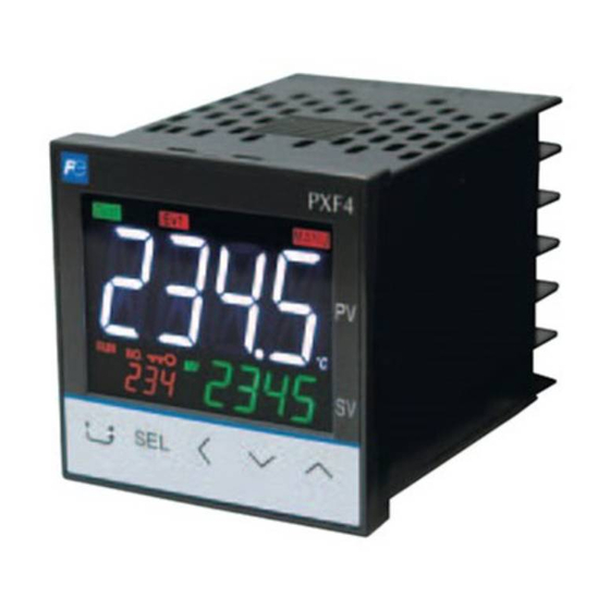
Part names and functions This section describes the names and functions of each part of the front panel. The front panel has the PV and SV displays, the status indicator lamps, and the setting keys, etc. Their functions are explained below. Please read and understand them before using the PXF. - Page 16 USER + ˄ key (15) A, %, kW/h indicator • Press and hold this key in PV/SV display to start the Shows the unit being applied to values on SV display assigned function. during the operation mode. (The factory set function for this key is switching between RUN and standby.) USER + ˅...
- Page 17 <PXF5/9> Operation keys Indicators USER key (1) Indicates process value (PV) • Press this key once in PV/SV display to switch between Shows parameter name when in parameter setting. SV display and MV display. (2) Set point (SV) • Press and hold this key in PV/SV display to start the Shows set value.
- Page 18 USER + ˄ key (15) A, %, kW/h indicator • Press and hold this key in PV/SV display to start the Shows the unit being applied to values on SV display assigned function. during the operation mode. (The factory set function for this key is switching (16) Bar graph between RUN and standby.) Shows MV.
-
Page 19: Digital Characters
Digit tal char racters The fo ollowing tabl les provide c corresponden nce between digital chara acters used fo or the display y of the cont t roller and al lphanumerica al characters s. (See the fo llowing table e for details. -
Page 20: Basic Ope Eration
asic O Opera ation Basic operati The belo ow figure illu ustrates the m mode transiti ion and the k key operation Operatio on mode In this m mode the norm mal operation n is performe ed. The proc cess value (P V) and the se et value (SV V) are display... -
Page 21: Chang Ging Sv (Set T Value)
anging S SV (set t value) [Desc cription] __ _________ _________ _________ _________ _________ _________ _________ ______ • The e SV is a targ get value for control. • SV must be with thin the range e between SV VL (lower lim mit) and SVH H (upper lim mit) which be... -
Page 22: Param Meters List
Param meters List The follo owing explai ins each chan nnel paramet ter. • The ra ange of the p parameters in n the shaded area indicate es the industr rial values. W When you ch hange the PV V input lower limit (Pvb), PV input up... -
Page 30: Paramete Er Functions S And Settin Ng Procedu Ure
aram eter f funct tions and s settin roced dure Opera ation m mode MAN A Auto/manua al switchov ver (001) [Descri ption] ____ _________ _________ _________ _________ _________ _________ _________ _____ Manual control allow ws you to set t the control o output to any y value. - Page 31 StbY RUN/Standby switchover (002) [Description] _______________________________________________________________ Allows you to switch between operation mode and standby mode. The following items used during standby can be set beforehand. • Control output (-5.0 to 105.0%) • Alarm output (ON/OFF) • Transfer output (ON/OFF) You can set the detail of standby mode in "Standby mode".
- Page 32 REM Remote/local switchover (003) [Description] ________________________________________________________________ The following will switch you between local SV and remote SV operation. In remote SV operation, SV is controlled by an external SV input (RSV). Note: During remote operation, you cannot change the SV by using UP/DOWN keys on the front panel. [Setting example] Switching to the remote SV mode ________________________________ Display Operating procedure...
- Page 33 PRoG Ramp Soak control command (004) [Description] _______________________________________________________________ Allows you to switch between Ramp/soak states. You can select among the following three state. • oFF (stop): Ramp/soak is stopped. • RUN (start): Ramp/soak starts. • HLd (hold): Ramp/soak hold. To release the hold, select "RUN" again. The parameter information changes automatically depending on the ramp/soak state.
- Page 34 AT Auto tuning (005) [Description] ________________________________________________________________ Running auto-tuning automatically sets the optimal PID. • Setting range oFF: Stop/Finish starts auto tuning (normal type) L-oN: starts auto tuning (low-PV type) There are the following two types in auto-tuning. Normal type Performs ON/OFF operation with SV as the baseline to calculate PID.
- Page 35 [Setting example] Running Auto-tuning _________________________________________ Display Operating procedure 245 Check that the PV/SV display is shown. Press the SEL key to move to operation mode. MAN ○ ○ ˄ ˅ keys to change MAN to At. Use the At Press the SEL key to enter At mode. (The lower part of the screen begins to blink.) ○...
- Page 36 LACH Alarm output latch release (006) [Description] ________________________________________________________________ Allows you to cancel the alarm Latch. • Setting range oFF: keeps the latch on RSt: releases latch [Setting example] Releasing alarm output latch ____________________________________ Display Operating procedure 245 Check that the PV/SV display is shown. Press the SEL key to move to operation mode.
- Page 37 SVN SV selection (007) [Description] _______________________________________________________________ Allows you to easily switch SV among the following. • Setting range: LoCL, SV1, SV2, SV3, SV4, SV5, SV6, SV7, di To use this function, you need to configure SVs (SV1 to SV7) in the PID palette parameters. It is recommended to activate the ramp SV before changing SV number so that control disorders can be reduced.
- Page 38 PLN1 PID selection (008) [Description] ________________________________________________________________ Allows you to easily switch PID No. among those you configured in the PID palette parameters. This allows you to change the PID according to the change of SV or control target. • Range: LoCL, Pid1, Pid2, Pid3, Pid4, Pid5, Pid6, Pid7, di [Setting example] Changing PID Number ________________________________________ Display Operating procedure...
- Page 39 AL1 A1-L A1-H Alarm settings (009 to 011) AL2 A2-L A2-H (012 to 014) AL3 A3-L A3-H (015 to 017) AL4 A4-L A4-H (018 to 020) AL5 A5-L A5-H (021 to 023) [Description] _______________________________________________________________ Allows you to set the values for alarm 1 to alarm 5. •...
- Page 40 WCMd Electric power calculation command (027) [Description] ________________________________________________________________ Allows you to switch the electric power calculation status among the following three modes. oFF: Stops calculation. (Calculated amount of electric power will be cleared.) RUN: Calculates the amount of electric energy. HLd: Suspend the calculation.
- Page 41 LoC Key lock (028) [Description] _______________________________________________________________ Prevents SV parameters from being changed. The following three settings are available: oFF: No lock ALL: All locked PARA: All but SV locked The channel menu can be displayed even when key lock is active. Related parameters: Accidental operation can also be prevented with a password.
-
Page 42: Ch1 Ppid (Control L Parameter Rs)
CH1 P PID (Co ontrol p parame eters) P Prop portional ba and (050) i Inte egration tim me (051) d Differ rential time e (052) [Descri ption] ____ _________ _________ _________ _________ _________ _________ _________ _____ Allows y you to set PID D (Proportio onal Band, In ntegration Ti... - Page 43 [Setting example] Setting P = 10.0%, I = 100sec., D = 20sec. ________________________ Display Operating procedure 245 Check that the PV/SV display is shown. Press and hold the SEL key to display CH1 (PID parameters). CH 1 Press the SEL key to enter CH1 (PID parameters). P is displayed.
- Page 44 HYS ON/OFF control hysteresis (053) [Description] ________________________________________________________________ Allows you to set the hysteresis for ON/OFF (2 position) control • Setting range: 0.0 to 50.0% FS The controllability varies with the size of the hysteresis. Small hysteresis • High-precision control • Frequency of output relays is high, so lifespan becomes short. Large hysteresis •...
- Page 45 CooL Cooling proportional band coefficient (054) [Description] _______________________________________________________________ Allows you to set the proportional band coefficient for cooling. • Setting range: 0.0 to 100.0 The relationship between heating control output and cooling control output is outlined below. Cooling proportional band is set after the optimal value for heating proportional band is set. Cooling proportional band = (Proportional band P/2) x Coefficient The following example shows how the cooling proportional band is calculated.
- Page 46 [Setting example] Changing cooling proportional band coefficient from 1.0 to 2.5 _________ Display Operating procedure 245 Check that the PV/SV display is shown. CH 1 Press and hold the SEL key to display CH1 (PID parameters). P Press the SEL key to enter CH1 (PID parameters). P is displayed.
- Page 47 db Dead band (055) [Description] _______________________________________________________________ Shifts the cooling proportional band against the set value as follows. "db" is called dead band when the value is positive, and overlap band when the value is negative. • Range: -50% to 50% "db"...
- Page 48 bAL Output convergence value (056) [Description] ________________________________________________________________ Output convergence value is a function that adds an offset to MV value. • Setting range bAL: -100 to 100% By this function, the bAL offset is added to original MV which is the result of PID calculation determined by PV and SV, and the total value is outputted as MV.
- Page 49 AR Anti-reset windup (057) [Description] _______________________________________________________________ Anti-reset windup is a function that limits the range of valid integration to control overshooting. Setting range Ar: 0 to 100% FS • The anti-reset windup function (“AR”) cuts integration that falls outside of the Ar set range that is centered around SV.
- Page 50 REV Normal/reverse operation (058) [Description] ________________________________________________________________ Specifies whether the control operations are normal or reverse. • Setting range RV_ _: heat (reverse) / cool (none) No_ _: heat (normal) / cool (none) RVNo: heat (reverse) / cool (normal) NoRV: heat (normal) / cool (reverse) RVRV: heat (reverse) / cool (reverse) NoNo:...
- Page 51 SVL SV lower limit (059) SVH SV upper limit (060) [Description] _______________________________________________________________ These parameters specify the setting range of the SV (Setting value). You can set any value within the measurement range. • Setting range: 0 to 100% FS (Upper/Lower) The relationship between SV limits and the measurement range is as follows: Note: •...
- Page 52 tC1 OUT1 proportional cycle (061) tC2 OUT2 proportional cycle (062) [Description] ________________________________________________________________ When using contact output and SSR drive output with PV input inside the proportional band, output will switch between ON and OFF at regular intervals. • These intervals are called proportional cycles. OUT1 and OUT2 can be set separately. Setting range: 1 to 150 The following are the recommended settings for each control output.
- Page 53 [Setting example] Setting OUT1 proportional cycle to 60 sec _________________________ Display Operating procedure 245 Check that the PV/SV display is shown. CH 1 Press and hold the SEL key to display CH1 (PID parameters). Press the SEL key to enter CH1 (PID parameters). P...
- Page 54 PLC1 PHC1 OUT1 Upper/Lower Limits (063, 064) PLC2 PHC2 OUT2 Upper/Lower Limits (065, 066) [Description] ________________________________________________________________ This parameter specifies the upper and lower limits for output control. • Setting range Output Lower limit Upper limit Setting range OUT1 PLC1 PHC1 -5.0 to 105.0% OUT2 PLC2...
- Page 55 PCUt Type of output limiter (067) [Description] _______________________________________________________________ You can choose whether to apply the limit on the output value or let it exceed the limit. The output changes according to the limit, as follows. Setting range Setting Output 1 (OUT1) Output 2 (OUT2) Lower limit Upper limit...
- Page 56 ALPA 2-degrees-of-freedom coefficient α (073) bEtA 2-degrees-of-freedom coefficient β (074) [Description] ________________________________________________________________ These coefficients are used to suppress overshoot generated in PID control. The 2-degrees-of-freedom PID system of this instrument adopts set value (SV) filter method, which is effective in suppressing overshoot at the time of setting change or start-up. If ALPA (α) is set to 100.0%, and bEtA (β) to 0.0%, ordinary PID control (1 degree of freedom PID) is performed.
- Page 57 [Setting example] Setting the 2-degrees-of-freedom coefficient α to 50.0% ______________ Display Operating procedure 245 Check that the PV/SV display is shown. CH 1 Press and hold the SEL key to display CH1 (PID parameters). Press the SEL key to enter CH1 (PID parameters). P...
-
Page 58: Ch2 Pplt (Pid Pa Lette Param Meters)
CH2 P PLT (P ID pale ette par ameter PID pale ette paramete ers are used t to register SV Vs, PIDs, an d other contr rol parameter ers. Up to sev ven sets of SV Vs and PIDs can n be stored, a and you can toggle amon... - Page 59 SV1 to SV7 Set Value (100 to 160) [Description] _______________________________________________________________ Up to seven SVs (SV1-SV7) can be recorded. Recorded SVs can be invoked by the SV selection ("Svn") parameter in the operation menu. Setting range: SV lower limit (SVL) to SV upper limit (SVH) %FS It is recommended to activate the ramp SV before changing SV number, so that control disorders can be reduced.
- Page 60 P1 to P7 Proportional band (101 to 161) i1 to i7 Integration time (102 to 162) d1 to d7 Differential time (103 to 163) [Description] ________________________________________________________________ These parameters allows you to configure PID. Up to seven types of PID (palettes 1 to 7) can be recorded. Recorded PIDs can be called from selected PID number ("PLN1") in the operation menu CH1.
- Page 61 [Setting example] Setting P = 10.0%, I = 100 sec., D = 20 sec. _______________________ Display Operating procedure 245 Check that the PV/SV display is shown. Press and hold the SEL key to display CH1 (PID parameters). CH 2 ○ ˅...
- Page 62 HYS1 to HYS7 ON/OFF control hysteresis (104 to 164) [Description] ________________________________________________________________ This parameter allows you to set the hysteresis width for the ON/OFF control. Up to seven types of hysteresis (for palettes 1 to 7) can be recorded. Recorded hysteresis can be called by PID selection ("PLN1") in the operation mode.
- Page 63 CoL1 to CoL7 Cooling Proportional Band (105 to 165) [Description] _______________________________________________________________ Allows you to set the cooling proportional band when dual outputs are selected. Up to seven types of cooling proportional band (for palettes 1 to 7) can be recorded. Recorded cooling proportional band can be called from PID selection (“PLN1”) in the operation mode.
- Page 64 db1 to db7 Dead band (106 to 166) [Description] ________________________________________________________________ Allows you to set the dead band when dual outputs are selected. Up to seven types of dead band (for palettes 1 to 7) can be recorded. Recorded dead band can be called from PID selection (“PLN1”) in the operation mode. •...
- Page 65 bAL1 to bAL7 Output convergence value (107 to 167) [Description] _______________________________________________________________ Allows you to set the output convergence value. Up to seven types of output convergence value (for palettes 1 to 7) can be recorded. Recorded output convergence value can be called from PID selection (“PLN1”) in the operation mode.
- Page 66 AR1 to AR7 Anti-reset windup (108 to 168) [Description] ________________________________________________________________ Allows you to set the anti-reset windup. Up to seven types of anti-reset windup (for palettes 1 to 7) can be recorded. Recorded anti-reset windup can be called from PID selection (“PLN1”) in the operation mode. •...
- Page 67 REV1 to REV7 Normal/reverse (109 to 169) [Description] _______________________________________________________________ Allows you to set the normal/reverse setting. Up to seven types of normal/reverse settings (for palettes 1 to 7) can be recorded. Recorded normal/reverse settings can be called from PID selection (“PLN1”) in the operation mode. Range Control operation RV_ _...
- Page 68 REF1 to REF7 PID palette switching point (170 to 176) [Description] ________________________________________________________________ This parameter allows you to set threshold value at which the controller automatically switches among PID palettes. • Setting range: 0 to 100% FS Related parameters: PID palette switching method (CH 7) (page 161) [Setting example] Setting the PID palette switching point 1 to 30% FS __________________ Display Operating procedure...
- Page 69 SVMX Max SV selection number (177) [Description] _______________________________________________________________ Allows you to set the maximum SV number that can be selected via the USER key. • Setting range: SV1 to SV7, LoCL, di Related parameters: "User key assignment" (CH 7) (page 141) [Setting example] Setting the max.
- Page 70 PL1M Max PID selection number (178) [Description] ________________________________________________________________ Allows you to set the maximum PID number that can be selected via the USER key. • Setting range: Pid1 to Pid7, LoCL, di Related parameters: "User key assignment" (CH 7) (page 141) [Setting example] Setting the max.
-
Page 71: Prg (Ramp Soak Param Meters)
3 PRG (Ramp soak p parame eters) This f function auto omatically ru uns according g to SVs and d the times fo or the SV cha anges configu ured previou u sly. You c can choose up p to 64 steps s for SV setti ing and 14 ty ypes of opera... - Page 72 PtN Ramp/soak operation pattern (Step No.) (200) [Description] ________________________________________________________________ The 64-step ramp/soak patterns are divided into 15 segments. You can choose any one to use. • Setting range steps 1 to 8 steps 1 to 16 steps 9 to 16 steps 17 to 32 steps 17 to 24 steps 33 to 48...
- Page 73 tiMU Ramp/soak time units (201) [Description] _______________________________________________________________ Allows you to set the time units for Ramp/soak operation. • Setting range: HH : MM(hour:min) MM : SS(min:sec) Note: Time units can not be set separately for each step. All steps use the same unit of time. [Setting example] Setting the time unit to MM:SS __________________________________ Display Operating procedure...
- Page 74 SV-1 to SV64 Ramp soak seg1 SV1 to seg64 SV64 (202 to 391) tM1R to t64R Ramp soak seg1 ramp time to seg64 ramp time (203 to 392) tM1S to t64S Ramp soak seg1 soak time to seg64 ramp time (204 to 393) [Description] ________________________________________________________________ Sets the ramp soak SV, ramp time and soak time.
- Page 75 [Setting example] Setting SV1, ramp time, and soak time for step1 ____________________ Display Operating procedure 245 Check that the PV/SV display is shown. Press and hold the SEL key to display CH1 (PID parameters). CH 3 ○ ˅ key to access CH3 (Ramp soak parameters). Press the PtN...
- Page 76 Mod Ramp soak mode (394) [Description] ________________________________________________________________ Allows you to set the method of ramp/soak operation. The following items can be set. Power-on start Starts ramp/soak with the current PV when the main unit is turned on. END time output Maintains the same state as at the end of ramp/soak when ramp/soak is complete.
- Page 77 [Setting example] Setting the ramp soak mode to 1 ________________________________ Display Operating procedure 245 Check that the PV/SV display is shown. Press and hold the SEL key to display CH1 (PID parameters). CH 3 ○ ˅ key to access CH3 (Ramp soak parameters). Press the PtN...
- Page 78 GSoK Guarantee soak (395) GS-L Guarantee soak band (lower) (396) GS-H Guarantee soak band (upper) (397) [Description] ________________________________________________________________ This function guarantees the soak time. Soak time is counted down only when PV is in the certain temperature range. As seen in the figure below, only the sum of the shaded areas is counted as soak time. The operation moves onto the next step when the total soak time has reached the specified soak time.
- Page 79 [Setting example] Setting guaranty soak to ON and upper/lower limits to 5°C ____________ Display Operating procedure 245 Check that the PV/SV display is shown. Press and hold the SEL key to display CH1 (PID parameters). CH 3 ○ ˅ key to access CH3 (Ramp soak parameters). Press the PtN...
- Page 80 PVSt PV start (398) [Description] ________________________________________________________________ When the ramp soak starts (RUN), this function searches the first point where the measurement value (PV) and the program pattern match, and starts operation at that point. If the measurement value does not match the pattern as with (3), the normal operation starts. Setting range: oN (PV start on), oFF (PV start off) [Setting example] Setting PV start to ON _________________________________________ Display...
- Page 81 CoNt Restore mode (399) [Description] _______________________________________________________________ This parameter specifies the ramp soak operation when the power is restored after being interrupted due to power outage or other reasons. Setting range RES: Does not operate ramp soak. CoN: Resumes the operation from the status of the time at which power is turned off.
- Page 82 PtNM Max pattern selection (400) PMiN Min pattern selection (401) [Description] ________________________________________________________________ Sets the max./min. pattern number that can be selected when proceeding the Ramp/soak activation pattern with USER keys. • Setting range: 0 to 14 • Related parameters: Ramp soak operation pattern (CH 3) (page 71) User key assignment (CH 7) (page 141) Note: Do not set a value for Min pattern selection that is larger than the value for Max pattern selection.
-
Page 83: Mon
4 MON (Monito or para ameters StAt Ramp soa ak progress s (420) [Desc cription] __ _________ _________ _________ _________ _________ _________ _________ ______ Displa ays the progr ress of the ra amp soak. The ra amp soak sta atus are indic cated as follo ows. - Page 84 MV1, MV2 Control output (MV1, MV2) (421, 422) [Description] ________________________________________________________________ Displays the output values (OUT1/OUT2). [Setting example] Checking the output value (OUT1) _______________________________ Display Operating procedure 245 Check that the PV/SV display is shown. Press and hold the SEL key to display CH1 (PID parameters). CH...
- Page 85 PFb PFB input value (423) [Description] _______________________________________________________________ Motorized valve opening will be displayed when using position feedback (PFB) as the control. [Setting example] Checking the PFB input value __________________________________ Display Operating procedure 245 Check that the PV/SV display is shown. Press and hold the SEL key to display CH1 (PID parameters).
- Page 86 RSV Remote SV (424) [Description] ________________________________________________________________ Displays the remote SV input value. [Setting example] Checking the remote SV input value ______________________________ Display Operating procedure 245 Check that the PV/SV display is show n. Press and hold the SEL key to display CH1 (PID parameters). CH...
- Page 87 Ct1 Heater current (425) [Description] _______________________________________________________________ Display the Heater current value. (The current value measured during the control output 1 is ON is indicated.) [Setting example] Checking the heater current value _______________________________ Display Operating procedure 245 Check that the PV/SV display is shown. Press and hold the SEL key to display CH1 (PID parameters).
- Page 88 LC1 Leak current (427) [Description] ________________________________________________________________ Display the Leak current value. (The current value measured during the control output 1 is OFF is indicated.) [Setting example] Checking the leak current value _________________________________ Display Operating procedure 245 Check that the PV/SV display is shown. Press and hold the SEL key to display CH1 (PID parameters).
- Page 89 tM1 to tM5 Remaining time on timer (429 to 433) [Description] _______________________________________________________________ Displays the remaining time on timer. Related parameters: ALM hysteresis, ALM delay, ALM delay time units (CH 5) (page 100) [Setting example] Checking the remaining time on the timer 1 ________________________ Display Operating procedure 245...
- Page 90 CoMM Communication status (435) [Description] ________________________________________________________________ Counts the number of communication times. If the counter has reached 9999, it restarts counting from zero. [Setting example] Checking the count ___________________________________________ Display Operating procedure 245 Check that the PV/SV display is shown. Press and hold the SEL key to display CH1 (PID parameters).
- Page 91 CUR1 Current (436) [Description] _______________________________________________________________ Displays the electric current value measured with CT. (The value is independent of the control output 1.) [Setting example] Checking the leak current value _________________________________ Display Operating procedure 245 Check that the PV/SV display is shown. Press and hold the SEL key to display CH1 (PID parameters).
- Page 92 PoW Electric power (438) [Description] ________________________________________________________________ Displays the calculated amount of electric power (kW). [Setting example] Checking the electric power ____________________________________ Display Operating procedure 245 Check that the PV/SV display is shown. Press and hold the SEL key to display CH1 (PID parameters). CH...
- Page 93 KWH Power (439) [Description] _______________________________________________________________ Displays the calculated amount of electric power. [Setting example] Checking the amount of electric power ___________________________ Display Operating procedure 245 Check that the PV/SV display is shown. Press and hold the SEL key to display CH1 (PID parameters). CH...
- Page 94 RCN1, RCN2 Number of operating times (440, 441) [Description] ________________________________________________________________ Displays the number of times that control output relay 1 or 2 has operated. The number is displayed in increments of 1000. (For example, when 1 is displayed, it means the relay has operated 1000 times.) [Setting example] Checking the number of operating times (control relay 1) ______________ Display Operating procedure...
- Page 95 RUNt Operating days (442) [Description] _______________________________________________________________ Displays the number of days that the temperature controller has been operated. [Setting example] Checking the number of days the controller has operated _____________ Display Operating procedure 245 Check that the PV/SV display is shown. Press and hold the SEL key to display CH1 (PID parameters).
- Page 96 FALt Error source (443) [Description] ________________________________________________________________ Displays the source of an error. (with hexadecimal number) 0 bit PV input underflow (LLLL) 1 bit PV input overflow (UUUU) 2 bit PV under range 3 bit PV over range 4 bit RSV under range 5 bit RSV over range 6 bit...
- Page 97 Di DI input state (444) [Description] _______________________________________________________________ Displays the state of DI (with hexadecimal number). 0 bit DI 1 1 bit DI 2 2 bit DI 3 3 bit DI 4 4 bit DI 5 [Setting example] Checking the DI input state ____________________________________ Display Operating procedure 245...
- Page 98 ERSt Communication error station number (445) [Description] ________________________________________________________________ Shows the station number under error and the detail of error during cooperative communication or programless communication. [Setting example] Checking the station number under communication error _____________ Display Operating procedure 245 Check that the PV/SV display is shown. Press and hold the SEL key to display CH1 (PID parameters).
- Page 99 PLNo Current PID No. (446) [Description] _______________________________________________________________ Displays the PID palette No. currently selected. [Setting example] Checking the PID number currently selected ______________________ Display Operating procedure 245 Check that the PV/SV display is shown. Press and hold the SEL key to display CH1 (PID parameters). CH...
- Page 100 PtNo Current pattern No. (447) [Description] ________________________________________________________________ Displays the ramp soak pattern No. currently selected. [Setting example] Checking the pattern number currently selected ____________________ Display Operating procedure 245 Check that the PV/SV display is shown. Press and hold the SEL key to display CH1 (PID parameters). CH...
-
Page 101: Alm
5 ALM ( (Alarm param eters) The al larm parame eters (CH5) c consists of th he following function blo cks. PXF4 can use ALM M1 to ALM3 PXF5 /9 can use A ALM1 to ALM Alarm m threshold v values are set t under ALM M1 to ALM5... - Page 102 A1tP to A5tP Alarm type (470, 475, 480, 485, 490) [Description] ________________________________________________________________ Set the alarm type for ALM1 to ALM5. You can select the alarm type from the below tables. 1-point alarm 2-point alarm What is alarm with hold? Timers and others The alarm will not turn ON immediately when the process value gets into the alarm band and enters again.
- Page 103 Note: • When alarm action code is changed, alarm set value may also become different from previous settings. • When alarm action type code is changed, turn off the power once, and then re-start the controller, before starting control. • ALn: indicates the alarm set values (AL1 to AL5). •...
- Page 104 A1HY to A5HY Alarm hysteresis (471, 476, 481, 486, 491) dLY1 to dLY5 Alarm delay (472, 477, 482, 487, 492) dL1U to dL5U Alarm delay time units (473, 478, 483, 488,493) [Description] ________________________________________________________________ Alarm parameter settings are as follows: Alarm hysteresis Specifies alarm detection width and recovery width.
- Page 105 [Setting example ] Setting the Alarm 1 hysteresis to 5°C, delay time to 30, and delay time unit to seconds__________________________________________________ Display Operating procedure 245 Check that the PV/SV display is shown. Press and hold the SEL key to display CH1 (PID parameters). CH...
- Page 106 AoP1 to AoP5 Alarm option (474, 470, 484, 489, 494) [Description] ________________________________________________________________ You can set the optional functions to the alarm 1 to the alarm 5, if you need. The four types of optional functions are assigned for each bit. •...
- Page 107 [Setting example] Adding the alarm latch and the converted output function to the alarm 1 _ Display Operating procedure 245 Check that the PV/SV display is shown. Press and hold the SEL key to display CH1 (PID parameters). CH 5 ○...
- Page 108 Hb1 Heater break alarm set value (500) Hb1H Heater break alarm hysteresis (501) [Description] ________________________________________________________________ This function controls whether the heater break alarm is active. The heater break alarm includes the following settings: Heater break alarm Settings The electric current set value at which the alarmtrips. •...
- Page 109 • The heater break detector CT is connected as shown below: • The heater break alarm is effective only for a singlephase power supply. It cannot be used for a threephase power supply. • The heater current detection is available only after the control output 1 has been working for at least 0.3 seconds.
- Page 110 CH 5 Press the SEL key to switch to CH1 (PID parameters). ○ ˅ key to access CH5 (Alarm parameters). Use the Press the SEL key to enter CH5 (Alarm parameters). AltP AltP (alarm type) is displayed. ○ ○ ˄ ˅...
- Page 111 HS1 Shorted-load alarm set value (502) HS1H Shorted load alarm hysteresis (503) [Description] _______________________________________________________________ These are the functions to detect short-circuiting of the SSR or Conductor. The setting items of the load short-circuit alarm are as follows: Load shortcircuit alarm Sets the electrical current value at which to detect a load short-circuit alarm.
- Page 112 LbtM Loop break detection time (508) LbAb Loop break detection range (509) [Description] ________________________________________________________________ This function detects if the control loop is broken. This function does not use a CT like the heater break alarm, while instead it checks the change of control output and PV to determine if the loop is broken.
- Page 113 [Setting example] Setting the loop break detection time to 600 sec. and detection range to 20°C ______________________________________________________ Display Operating procedure 245 Check that the PV/SV display is shown. Press and hold the SEL key to display CH1 (PID parameters). CH 5 ○...
- Page 114 WHAL Electricity alarm (511) [Description] ________________________________________________________________ Allows you to set the value for electricity alarm. The electricity alarm will be activated when the amount of electric power has reached the setpoint. • Setting range Decimal point position for Setting range electric power (WdP) 0 to 9999 kWh 0.0 to 999.9 kWh...
- Page 115 SET (S Setup p paramet ters) PVt P PV input ty ype (530) [Desc cription] __ _________ _________ _________ _________ _________ _________ _________ ______ Allow ws you to sele ect PV input source from m thermocoup ples, RTD, an nd others. Note: •...
- Page 116 PVb PV input lower limit (531) PVF PV input upper limit (532) [Description] ________________________________________________________________ Allows you to set the upper/lower limit of PV input within the measurement range. Setting range: -1999 to 9999 Note: • Be sure to set the values so that PVF is greater than PVb.
- Page 117 PVd Decimal point position (533) [Description] ______________________________________________________________ Sets the decimal point position for the PV. • Setting range 0: No digit after decimal point 1: 1 digit after decimal point 2: 2 digit after decimal point 3: 3 digit after decimal point •...
- Page 118 CUt Square-root extractor cut point (535) [Description] ________________________________________________________________ Square root extractions • To convert differential pressure to flow rate, square root extraction is used. Where the differential pressure is small, the differential pressure to the router cut point is handled as zero, because under such a condition flow fluctuation or noise affects largely on readings.
- Page 119 PVoF PV input shift (536) [Description] _______________________________________________________________ This function shifts PV input before display. This function can be used to make the SV value correspond with other instruments. • Setting range: -10 to 10% FS [Setting example] Setting the PV input shift to -5.0°C _______________________________ Display Operating procedure 245...
- Page 120 SVoF SV shift (537) [Description] ________________________________________________________________ This function specifies the SV shift. This is used to eliminate remaining offset when using P control. • Controls act on the calculated SV with SV offset. • Alarm determination acts on the displayed SV without SV offset. •...
- Page 121 tF PV input filter (538) [Description] _______________________________________________________________ This low-pass filter function reduces noise and signal fluctuation. • Setting range: 0.0 to 120.0 sec. (input filter time constant) If the input filter time constant is set to 5 and input is changed from 0 to 100%, the PV display gradually changes, and it takes about 5 seconds for the value to change from 0 to 63.2%, as shown in the figure below.
- Page 122 AdJ0 PV display zero adjustment (539) AdJS PV display span adjustment (540) [Description] ________________________________________________________________ This is the procedure for adjusting the PV display zero/span. Set the following equipment before using these parameters or starting revisions. • mv Generator 1V to 5V (for voltage/current input) 0mV to 100mV (for thermocouple input) •...
- Page 123 [Setting example] Adjusting zero and span in PV display ____________________________ Display Operating procedure Confirm the accuracy of PV display by checking PV display when an mV generator or a dial resistor is set to 0% and 100%. This example assumes a zero deviation of -3°C and a span deviation of 4°C.
- Page 124 RCJ Cold junction compensation (541) [Description] ________________________________________________________________ This is the procedure for turning cold junction compensation on or off when using input from a thermocouple sensor. This setting should be left "ON" during normal operation. It should oly be turned off when cold junction compensation is being performed externally or you wish to record temperature differences.
- Page 125 REMO Remote SV zero adjustment (543) REMS Remote SV span adjustment (544) [Description] _______________________________________________________________ This function adjusts remote SV zero/span. Use this function to match zero/span to an output gauge. • Range: -50% to 50% FS (zero/span) If the input range is 1 V to 5 V, zero and span adjustment shall be as follows. PV display 100% Span adjustment...
- Page 126 [Setting example] Adjusting zero and span in PV display ____________________________ Display Operating procedure Confirm the accuracy of PV display by checking PV display when an output gauge or a dial resistor is set to 0% and 100%. This example assumes a zero deviation of -5% and a span deviation of 7%.
- Page 127 REMR Remote SV input range (545) [Description] _______________________________________________________________ This is the procedure for specifying the remote SV input range. • Range 0-5V: 0V to 5V 1-5V: 1V to 5V 0-10: 0V to 10V 2-10: 2V to 10V [Setting example] Setting the remote SV input range to 0-5V _________________________ Display Operating procedure 245...
- Page 128 RtF Remote SV input filter (546) [Description] ________________________________________________________________ This low-pass filter function reduces noise and signal wavering. • Range: 0.0 sec to 120.0 sec (input filter damping) When the input suddenly steps from 0% to 100% with the input filter constant set to 5 seconds, the remote SV display will change slowly and take 5 seconds to change from 0% to 63.2%.
- Page 129 C1R OUT1 range (547) C2R OUT2 range (548) [Description] _______________________________________________________________ Allows you to set the range of the control output 1(OUT1, OUT2). • Setting range 0-5V: 0 to 5 V 1-5V: 1 to 5 V 0-10: 0 to 10 V 2-10: 2 to 10 V 0-20: 0 to 20 mA 4-20: 4 to 20 mA...
- Page 130 FLo1 MV1 during FALT (549) FLo2 MV2 during FALT (550) [Description] ________________________________________________________________ Allows you to specify the control output values when the controller falls into FALT (input error). • Setting range: -5.0% to 105.0% (OUT1/OUT2) [Setting example] Setting the OUT1/OUT2 during FALT to 5% ________________________ Display Operating procedure 245...
- Page 131 SFo1 MV1 during soft start (551) SFtM Soft start set time (553) [Description] _______________________________________________________________ This function controls the maximum output produced when turning on the equipment (including the temperature controller). The controls place an upper limit on the output for a set time period after the power is turned on. This function is useful for effects such as suppressing the heater output during equipment startup, or lightening the load.
- Page 132 [Setting example] Setting OUT1 during soft start to 5%, and time to 30 minutes __________ Display Operating procedure 245 Check that the PV/SV display is shown. Press and hold the SEL key to display CH1 (PID parameters). CH 6 ○ ˅...
- Page 133 Sbo1 MV1 during standby (554) Sbo2 MV2 during standby (555) [Description] _______________________________________________________________ Allows you to set the control output values used during standby mode. • Setting range: -5.0% to 105.0% (OUT1/OUT2) [Setting example] Setting OUT1 during standby to 5% ______________________________ Display Operating procedure 245...
- Page 134 SbMd Standby mode (556) [Description] ________________________________________________________________ Allows you to specify the alarm action during standby. Select the alarm action and transfer output during standby among the following four combinations. Setting range SbMd Alarm action Transfer output Suspends the alarm action. (alarm output OFF) Continues to output.
- Page 135 Aot AO output type (557) [Description] _______________________________________________________________ This is the procedure to specify what output is retransmitted. The following five settings are available: • Range Pv: Measurement Sv: Set value Mv: Control output Dv: Variable (PV-SV) PFb: Position Feedback (Do not select this if you ordered the version without PFB input.) [Setting example] Setting the AO output type to SV _______________________________ Display Operating procedure...
- Page 136 AoL AO lower scaling (558) AoH AO upper scaling (559) [Description] ________________________________________________________________ This is the procedure for specifying the upper and lower limits of re-transmission input. • Range: -100% to 100% FS (Upper/lower limit) Calculate the set value with the following equation. (Use the example set value below as a reference.) Set value (%) = (A ÷...
-
Page 137: Set
[Setting example] Setting the AO lower scaling to -80%, upper scaling to 80% ___________ Display Operating procedure 245 Check that the PV/SV display is shown. Press and hold the SEL key to display CH1 (PID parameters). CH 6 ○ ˅ key to access CH6 (Setup parameters). Use the PVt... - Page 138 VoLt Fixed voltage value (561) CRU Current value for simple power calculation (562) iMiN Electric current nullification point (563) WdP Decimal point position for electric power (564) PHY Power factor for simple calculation (565) [Description] ________________________________________________________________ These parameters are used for calculating the amount of electric power, based on the time duration that the control output relay 1 has operated.
- Page 139 [Setting example] Setting the voltage to 150 V, current to 1.2 A, decimal place to 0.01 _____ Display Operating procedure 245 Check that the PV/SV display is shown. Press and hold the SEL key to display CH1 (PID parameters). CH 6 ○...
- Page 140 RYCN Upper limit of relay contact operation (566) [Description] ________________________________________________________________ Allows you to set the upper limit on the number of times that the control output relay 1 and 2 can operate. The alarm will be activated when the control output relay 1 or 2 has operated the number of times you set. •...
- Page 141 oPtM Upper limit of operating days (567) [Description] _______________________________________________________________ Allows you to set the upper limit on the number of days that the device can operate. The alarm will be activated when the number of operating days has reached the setpoint. •...
-
Page 142: Ch7 Ssys (System M Paramete Ers)
CH7 S SYS (Sy ystem p parame eters) UKY1 U USER key y assignme ent (590) UKY2 U USER key y assignme ent (591) UKY3 U USER key y assignme ent (592) [Descri ption] ____ _________ _________ _________ _________ _________ _________ _________ _____... - Page 143 [Setting example] Assigning the switchover between STBY ON/OFF to the USER key _____ Display Operating procedure 245 Check that the PV/SV display is shown. Press and hold the SEL key to display CH1 (PID parameters). CH 7 ○ ˅ key to access CH7 (System parameters). Use the Press the SEL key to enter CH7 (System parameters).
- Page 144 di1 to di5 DI function select (593 to 597) [Description] ________________________________________________________________ You can allocate one of the following functions to each of DI1 to DI5. These functions are activated by external DI signals. Function Action Criteria No function No action Cancels Standby ON/OFF switchover Switches between Standby ON/OFF.
- Page 145 Function Action Criteria Pattern No. + 4 Increases the pattern number by 4. Level Pattern No. + 8 Increases the pattern number by 8. Level DI soft start Starts DI soft start. Start Edge Setting prohibited Delay start (alarm 1) Enables delay start with the delay time = dLY1.
- Page 146 oU1t OUT1 output type (599) oU2t OUT2 output type (600) do1t to do3t Output type (DO1 to DO3) (601 to 603) LoU1 LED indicator assignment (OUT1) (607) LoU2 LED indicator assignment (OUT2) (608) LEV1 to LEV6 LED indicator assignment (EV1 to EV6) (609 to 614) LStb LED indicator assignment (STBY) (615) LMAN LED indicator assignment (MAN) (616) [Description] ________________________________________________________________...
- Page 147 [Setting example] Setting MV1 to be output from OUT1 , alarm output 1 from DO1, alarm output 1 from OUT1 indicator __________________________________ Display Operating procedure 245 Check that the PV/SV display is shown. Press and hold the SEL key to display CH1 (PID parameters). CH...
- Page 148 RMP Ramp SV ON/OFF (617) RMPL Ramp SV-decline (618) RMPH Ramp SV-incline (619) RMPU Ramp SV-slope time unit (620) [Description] ________________________________________________________________ This function changes a SV to the new value at the preset ramp rate. SV changes smoothly, not stepwise. Incline and decline rates can be set independently. •...
- Page 149 [Setting example] Setting the ramp SV incline to 10°C/min, and decline to 5°C/min _______ Display Operating procedure 245 Check that the PV/SV display is shown. Press and hold the SEL key to display CH1 (PID parameters). CH 7 ○ ˅ key to access CH7 (System parameters). Use the UKY1...
- Page 150 SVt Ramp SV display mode (621) [Description] ________________________________________________________________ Selects which to display between the SV during ramp operations or the SV goal value. [Setting example] Setting the target SV to be displayed _____________________________ Display Operating procedure 245 Check that the PV/SV display is shown. Press and hold the SEL key to display CH1 (PID parameters).
- Page 151 CtRL Control method (622) [Description] _______________________________________________________________ This controller has six temperature control functions. Select the best control method for your application. ● Temperature control functions ON/OFF (2-position) Switches output control ON/OFF according to the SV/PV magnitude control relationship. Control systems can be built from simple elements such as SSR.
- Page 152 Normal operation (Cooling) Method used to control the cooling machine. Parameter Set value CtRL oNoF No_ _ optional (default: 1°C) • During ON/OFF control, the P, I and D settings do not affect control. • In the manual operation during ON/OFF control, MV displayed by pressing UP key is 100%, and MV displayed by pressing DOWN key is 0%.
- Page 153 • During manual mode • During soft start Conditions where self-tuning is halted • When SV is changed (including when SV is changed by the ramp/soak function, remote SV function, or ramp SV.) • When self-tuning has not finished after running for nine or more hours •...
- Page 154 [Setting example] Setting the control method to ON/OFF control ______________________ Display Operating procedure 245 Check that the PV/SV display is shown. Press and hold the SEL key to display CH1 (PID parameters). CH 7 ○ ˅ key to access CH7 (System parameters). Use the Press the SEL key to enter CH7 (System parameters).
- Page 155 S Control target (623 [Desc cription] __ _________ _________ _________ _________ _________ _________ _________ ______ This c controller has s three valve e control func ctions. Select t the best fun nction for the e current app plication. ●V Valve Contro ol Functions ervo control Controls...
- Page 156 [Setting example] Changing the control target from servo1 to servo2 __________________ Display Operating procedure 245 Check that the PV/SV display is shown. Press and hold the SEL key to display CH1 (PID parameters). CH 7 ○ ˅ key to access CH7 (System parameters). Use the Press the SEL key to enter CH7 (System parameters).
- Page 157 (2) Position Feedback Control (PFB control) Position feedback control (PFB) is used to control the position of the motorized valve based on the position signal transmitted from the motorized valve. During manual mode, the controller displays the valve position signal as MV. Because it is based on the actual valve position, PFB control is more precise than the servo 1/servo 2 control.
- Page 158 oNoF ONOFF Hysteresis (624) [Description] ________________________________________________________________ Selects the hysteresis operation during two state action. OFF: Performs two state action at SV+HYS/2 and SV-HYS/2. ON: Performs two state action at SV, SV+HYS and SV, SVHYS. oNoF: OFF oNoF: ON Reverse Normal Operation [Setting example] Setting the start mode to control output manual mode ________________ Display Operating procedure...
- Page 159 StMd Start mode (626) [Description] _______________________________________________________________ Allows you to specify the mode that the device starts up. Select from the following four options. • Setting range AUto Control output auto mode Control output manual mode Remote SV mode StbY Standby Mode [Setting example] Setting the start mode to control output manual mode ________________ Display Operating procedure...
- Page 160 dt Control operation cycle (627) [Description] ________________________________________________________________ Allows you to set the control operation cycle. Note: Be sure to restart the controller after changing the setpoint. Setting range: 0.1 to 0.9 s, 1 to 99 s [Setting example] Setting the control operation cycle to 0.2 seconds. ___________________ Display Operating procedure 245...
- Page 161 PLtS PID palette switching method (628) [Description] _______________________________________________________________ This instrument is provided with 7 groups of control palettes (group of control parameters) in CH2 (PLT), in addition to control parameters in CH1 (PID). Control can be made while switching these control palettes. Select control palette switching method with PLTS parameter.
- Page 162 [Setting example] Switching palettes by SV selection No. ____________________________ Display Operating procedure 245 Check that the PV/SV display is shown. Press and hold the SEL key to display CH1 (PID parameters). CH 7 ○ ˅ key to access CH7 (System parameters). Use the Press the SEL key to enter CH7 (System parameters).
-
Page 163: Ch8 Mmath (Calc Ulation Para Ameters)
8 MATH H (Calcu ulation param eters) MAtH H Simple c calculation ON/OFF ( 650) MA to MAo4 4 Simple c calculation setting an d result (6 51 to 730) 1 to CoNA A Constant setting (73 31 to 740) [Desc cription] __ _________... - Page 164 You can use the following values as inputs for calculation. Category Function No input Alarm 1 Alarm 2 Alarm output Alarm 3 Alarm 4 Alarm 5 Ramp soak (OFF) Ramp soak (RUN) Ramp soak event output Ramp soak (HOLD) Guarantee soak (GS) Ramp soak (END) Simple calculation result wafer 1 output 1 Simple calculation result wafer 1 output 2...
- Page 165 (1) Simple calculation ON/OFF (MAtH) (650) Allows you to switch between ON/OFF of simple calculation. Setting range: ON, OFF (2) Calculation setting (wafer 1 to wafer 10) (W1MA to WAMA) (651 to 723) Allows you to set the contents of wafer calculation. Setting range: 1 to 6 (3) Input 1 setting (wafer 1 to wafer 10) (W1i1 to WAi1) (652 to 724) Input 2 setting (wafer 1 to wafer 10) (W1i2 to WAi2) (653 to 725)
- Page 166 Display Operating procedure 245 Check that the PV/SV display is shown. Press and hold the SEL key to display CH1 (PID parameters). CH 8 MAtH ○ ˅ key to access CH8 (Calculation parameters). Use the MAtH Press the SEL key to enter CH8 (Calculation parameters). MAtH (simple calculation ON/OFF) is displayed.
-
Page 167: Com
3-10 9 COM (Comm municat ion par rameter This d device uses a an RS-485 in nterface and c can therefore e communica ate with pers onal comput ters, program mmable operat tion indicato ors, and other r devices. Th hese paramete ers set the co ommunicatio... - Page 168 CtyP Communication type (760) [Description] ________________________________________________________________ Selects the type of communication. • Setting range MODBUS RTU Cooperative operation Programless communication Their functions are as follows: Refer to the "Micro Controller (Model: PXF) Communication Function Manual (MODBUS)" for the detail. Typical master/stave communication is available. A PC or PLC acts as 0: MODBUS RTU a master, while multiple temperature controllers act as as slaves.
- Page 169 StNo Station No. (761) [Description] _______________________________________________________________ Allows you to set the station number. • Setting range: 0 to 255 (Note that setting the station number to 0 will suspend communication.) If there are two or more slave devices, make sure that they do not have the same station numbers. If two devices on the same network share a station number, communication becomes unavailable.
- Page 170 SPEd RS485 baud rate (762) [Description] ________________________________________________________________ Allows you to set the baud rate of RS-485 communication. • Setting range: 96 (9600 bps), 192 (19200 bps), 384 (38400 bps), 115 k (115 kbps) Note: Be sure to restart the controller after changing the setpoint. [Setting example] Setting the baud rate to 19200 bps _______________________________ Display Operating procedure...
- Page 171 PRtY RS-485 parity (763) [Description] _______________________________________________________________ Allows you to set the parity check of RS-485 communication. • Setting range: NoNE (no parity), odd, EVEN Note: Be sure to restart the controller after changing the setpoint. [Setting example] Setting the RS-485 parity to NoNE (no parity) ______________________ Display Operating procedure 245...
- Page 172 iNtV RS-485 response interval (764) [Description] ________________________________________________________________ Allows you to set the time interval before sending response. Setpoint x 20 ms makes the response interval time. • Setting range: 0 to 100 [Setting example] Setting the responce interval to 40 ms ____________________________ Display Operating procedure 245...
- Page 173 SCC Communication permission (767) [Description] _______________________________________________________________ Allows you to specify whether the master is permitted or forbidden to write to the slave. • Setting range R: read only RW: read/write [Setting example] Enabling the write protection ___________________________________ Display Operating procedure 245...
- Page 174 UA01 to UA32 MODBUS user address setting 1 to 32 (769 to 800) [Description] ________________________________________________________________ By registering a MODBUS communication address with the user address area, you can read/write the data of addresses through one communication even if those address are not sequential. You can register 32 addresses maximum.
- Page 175 • Cooperative operation parameters CSVG Communication SV gain (801) CSVS Communication SV shift (802) kykd Cooperative operation items (803) APCy All parameters copy (804) • Programless communication parameters PLSt Target PLC station No. (805) PAdk PLC registration number allocation rule (806) MSWt Communication interval between temperature controllers (807) PLWt Communication interval between PLC and temperature controllers (808) PLAd Head of PLC registration numbers (809)
- Page 176 AFix Auto Fix (842) [Description] ________________________________________________________________ Sets whether or not to automatically save parameter values that are written via communication onto EEPROM. • Setting range oN: Automatic data save oFF: No data save [Setting example] No data save ________________________________________________ Display Operating procedure 245...
- Page 177 10 PFB (PFB p parame eter) AP PFB dea ad band (8 870) [Desc cription] __ _________ _________ _________ _________ _________ _________ _________ ______ The d ead band can n be set to no ot output the valve open o or close sign nal.
- Page 178 tRVL Valve stroke time (871) [Description] ________________________________________________________________ This function controls the time it takes for the motorized valve to go from fully open to fully closed. Refer to the motorized valve makerís catalog for the correct stroke time. • Range: 5 sec to 180 sec [Setting example] Setting the valve stroke time to 50 seconds _______________________ Display Operating procedure...
- Page 179 CAL PFB input adjustment (873) [Description] _______________________________________________________________ This function adjusts whether PFB input is zero (fully closed) or span (fully opened). There are automatic and manual methods for adjusting. Setting Function Explanation None/forcible termination Ends adjustment immediately Zero adjustment Manually adjust zero Span adjustment Manually adjust span Automatic adjustment...
- Page 180 MANU Press the key to return to the PV/MV display. 245 ○ ˄ key. Fully open the motorized valve by using the Press and hold the SEL key to display CH1 (PID parameters). CH10 ○ ˅ key to access CH10 (PFB parameters). Use the PGAP...
- Page 181 Making the adjustment automatically The following steps explain how to make adjustments to zero and span automatically. • In automatic adjustment, the controller fully opens or fully closes the motorized valve to make zero and span adjustment for PFB input. The controller also change the valve stroke time "TrvL" to the optimal value. •...
- Page 182 [Setting example] Making the adjustment automatically _____________________________ Display Operating procedure 245 Check that the PV/SV display is shown. Change to the manual mode. MANU (Refer to “auto/manual switchover” on page 29.) 245 Press and hold the SEL key to display CH1 (PID parameters). ○...
-
Page 183: Ch11 1 Dsp (Para Ameter Mas Sk)
3-12 CH11 1 DSP ( (Param meter m mask) dp01 Paramete er mask [Desc cription] __ _________ _________ _________ _________ _________ _________ _________ ______ • The e parameter m mask allows you to hide unused param meters or to skip over the e parameters s you want to o keep... - Page 184 3-13 CH12 CFG (C Configu uration parame eters) toUt Op peration tim meout (940 [Descri ption] ____ _________ _________ _________ _________ _________ _________ _________ _____ • Sets th he time until l the display returns to the e PV/SV scr reen when no o operation is s made durin...
- Page 185 SoFK Blinking SV during soft start (942) [Description] _______________________________________________________________ • Specifies whether or not to blink “SoFT” on SV display during soft start. • Setting range: oFF: does not display “SoFT” and SV alternately. oN: displays “SoFT” and SV alternately. [Setting example] Setting not to blink SoFt _______________________________________ Display Operating procedure...
- Page 186 ALMF Blinking PV/SV at ALM (943) [Description] ________________________________________________________________ • Specifies the contents displayed when an alarm occurs. Setting Function Displays PV (no change) Displays PV and the alarm status alternately Displays flashing PV Displays the alarm status only (PV is not displayed) •...
- Page 187 [Setting example] Setting to display only the alarm status during an alarm ______________ Display Operating procedure 245 Check that the PV/SV display is shown. Press and hold the SEL key to display CH1 (PID parameters). CH12 ○ ˅ key to display CH12 (Configuration parameters). Press the Press the SEL key to enter CH12 (Configuration parameters).
- Page 188 LoFF Display timeout (944) [Description] ________________________________________________________________ With this function, the displays and indicator lamps are automatically turned off if the specified time passed without any key operation. Setting Function Displays stay ON 15 S Displays are turned off 15 seconds after the last key operation.
- Page 189 dSPt PV/SV display OFF (945) [Description] _______________________________________________________________ This parameter is used to manually turn off the PV, SV, and LED lamps on PV/SV screen. Setting Function PV, SV, and LED lamps stay ON SV display OFF PV display OFF PV and SV displays OFF PV, SV, and LED lamps OFF SV display OFF (relights for 5 sec.
- Page 190 FLtF Blinking PV at input error (946) [Description] ________________________________________________________________ Allows you to set whether or not to blink PV during an input error (UUUU, LLLL, ERR). Setting Function PV blinks during an input error PV does not blink during an input error [Setting example] Setting PV display not to blink during an input error __________________ Display Operating procedure...
- Page 191 bLit Brightness (947) [Description] _______________________________________________________________ Allows you to set the brightness of LED backlight. • Setting range: 0 to 3 (3 is the brightest) [Setting example] Setting the brightness to 0 (the darkest) __________________________ Display Operating procedure 245 Check that the PV/SV display is shown. Press and hold the SEL key to display CH1 (PID parameters).
- Page 192 bCoN Control at burnout (948) [Description] ________________________________________________________________ Allows you to set whether to continue or to stop control when the device detects a burnout of PV input. • Setting range: oN: continues control oFF: Stop control (control output depends on the set values of FL01 and FL02.) [Setting example] Setting to continue the control at burnout __________________________ Display Operating procedure...
- Page 193 PL01 to PL13 Model code (950 to 962) [Description] _______________________________________________________________ Displays the model code of the controller. [Setting example] Checking the model code ______________________________________ Display Operating procedure 245 Check that the PV/SV display is shown. Press and hold the SEL key to display CH1 (PID parameters). CH12...
- Page 194 RSt Reset (963) [Description] ________________________________________________________________ Allows you to reset the controller without recycling the power. • Setting range: oFF: do nothing RSt: reset the controller Resetting the controller is equivalent to turning the power off and on. [Setting example] Resetting the controller ________________________________________ Display Operating procedure 245...
- Page 195 VER1 to VER4 Software version (965 to 968) [Description] _______________________________________________________________ You can check the software version. [Setting example] Checking the software version __________________________________ Display Operating procedure 245 Check that the PV/SV display is shown. Press and hold the SEL key to display CH1 (PID parameters). CH12...
-
Page 196: Ch13 3 Pass (Pa Assword Par Rameters)
3-14 CH13 PASS ( (Passw word pa aramete ers) PAS1 t to PAS3 Pa assword se etup (990 t to 992) [Descri ption] ____ _________ _________ _________ _________ _________ _________ _________ _____ Allows y you to hide a a bundle of ch hannels. - Page 197 [Setting example] Setting the password for parameter change _______________________ Display Operation procedure 245 Check that the PV/SV display is shown. Press and hold the SEL key to display CH1 (PID parameters). CH13 ○ PASS ˅ key to access CH13 (Password parameters). Use the Press the SEL key to enter CH13 (Password parameters).
-
Page 198: Trouble Eshootin Ng
TROUBLESHOOTING When a trouble occurs, first check the model, wiring, and parameter settings. The following table shows some typical cases and their solutions. Trouble Cause Solution Reference Ch. Screen No. Cannot communicate Parity does not agree. Make the parity on the host and the unit No.
Need help?
Do you have a question about the PXF-2 and is the answer not in the manual?
Questions and answers