
Subscribe to Our Youtube Channel
Related Manuals for Swann AMI Deltacon Power

Summary of Contents for Swann AMI Deltacon Power
- Page 1 A-96.250.451 / 190121 Operator’s Manual Firmware V6.21 and higher AMI Deltacon Power...
- Page 2 For any technical question, contact your nearest Swan representative, or the manufacturer: Swan Analytische Instrumente AG Studbachstrasse 13 8340 Hinwil Switzerland Document Status AMI Deltacon Power Operator’s Manual Title: A-96.250.451 Revision Issue Sept. 2009 Preliminary Edition Nov. 2009 Update to FW Release 4.12...
-
Page 3: Table Of Contents
AMI Deltacon Power Table of Contents Safety Instructions .......... - Page 4 AMI Deltacon Power Maintenance ........... 37 6.1.
-
Page 5: Safety Instructions
AMI Deltacon Power Safety Instructions AMI Deltacon Power– Operator’s Manual This document describes the main steps for instrument setup, opera- tion and maintenance. Safety Instructions General The instructions included in this section explain the potential risks associated with instrument operation and provide important safety practices designed to minimize these risks. -
Page 6: Warning Notices
AMI Deltacon Power Safety Instructions 1.1. Warning Notices The symbols used for safety-related notices have the following meaning: DANGER Your life or physical wellbeing are in serious danger if such warn- ings are ignored. Follow the prevention instructions carefully. - Page 7 AMI Deltacon Power Safety Instructions Warning Signs The warning signs in this manual have the following meaning: Electrical shock hazard Corrosive Harmful to health Flammable Warning general Attention general A-96.250.451 / 190121...
-
Page 8: General Safety Regulations
AMI Deltacon Power Safety Instructions 1.2. General Safety Regulations Legal The user is responsible for proper system operation. All precautions must be followed to ensure safe operation of the instrument. Requirements Spare Parts Use only official SWAN spare parts and disposables. If other parts are used during the normal warranty period, the manufacturer’s war-... -
Page 9: Restriction For Use
AMI Deltacon Power Safety Instructions 1.3. Restriction for use The AMI Deltacon Power is designed for determination of: specific (total) conductivity cation (acid) conductivity after the cation exchanger in power plant water. It calculates the pH value and the concentration of the alkaline sub- stance (NH , morpholine, etc.) if an alkaline substance is present in... -
Page 10: Product Description
Product Description 2.1. Description of the System Application The AMI Deltacon Power is a complete monitoring system for the au- tomatic, continuous measurement of the total (specific) conductivity Range before a cation exchanger and the cation (acid) conductivity after a cation exchanger. - Page 11 AMI Deltacon Power Product Description Alarm Relay One potential free contact alternatively: Open during normal operation, closed on error and loss of power. Closed during normal operation, open on error and loss of power. Summary alarm indication for programmable alarm values and in- strument faults.
- Page 12 The temperature is measured with the temperature sensors integrat- ed in the conductivity sensors. Pre-rinse The AMI Deltacon Power with pre-rinse option allows fast replace- ment of the cation exchanger because the resin is pre-rinsed. Pre- Option rinsing has the effect to remove disturbing contaminations contained in the resin, which may cause incorrect measuring values.
- Page 13 AMI Deltacon Power Product Description Fluidics overview First conductivity sensor Flow meter Flow cell block Sample collector Flow regulating valve Deaeration tube cation Pre-rinse inlet exchanger bottle Pre-rinse outlet Deaeration tube pre-rinse Pre-rinsed cation exchanger bottle bottle Active cation exchanger...
-
Page 14: Instrument Specification
AMI Deltacon Power Product Description 2.2. Instrument Specification Power Supply AC variant: 100–240 VAC (±10%) 50/60 Hz (±5%) DC variant: 10–36 VDC Power consumption: max. 35 VA Sample Flow rate: 5–20 l/h Temperature: up to 50 °C requirements Inlet pressure:... - Page 15 AMI Deltacon Power Product Description Dimensions Panel: stainless steel Dimensions: 280 x 850x 200 mm Screws: 5 mm or 6 mm diameter Weight: 10 kg A-96.250.451 / 190121...
-
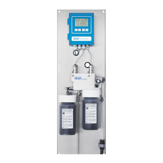
Page 16: Instrument Overview
AMI Deltacon Power Product Description 2.3. Instrument Overview Panel Flow regulating valve Transmitter Sample collector Specific conductivity sensor Active cation exchanger Cation conductivity sensor Pre-rinsed cation exchanger Flow cell Sample inlet Flow meter Sample outlet A-96.250.451 / 190121... -
Page 17: Installation
AMI Deltacon Power Installation Installation 3.1. Installation Checklist Monitors On-site AC variant: 100–240 VAC (±10%), 50/60 Hz (±5 %) requirements DC variant: 10–36 VDC Power consumption: 35 VA maximum Protective earth connection required Sample line with sufficient sample flow and pressure (see Instrument Specification, p. -
Page 18: Mounting Of Instrument Panel
AMI Deltacon Power Installation 3.2. Mounting of Instrument Panel The first part of this chapter describes the preparing and placing of the system for use. The instrument must only be installed by trained personnel. Mount the instrument in vertical position. -
Page 19: Fep Tube At Sample Outlet
AMI Deltacon Power Installation Stainless steel tube Compression cone Union nut Body Compression ferrule Tightened connection 3.3.2 FEP Tube at Sample Outlet 1/2” Tube at waste funnel. Waste funnel Hose nozzle 1/2” tube Connect the 1/2” tube [C] to the hose nozzle [B] and place it into a drain with atmospheric pressure. -
Page 20: Installation Of Cation Exchanger
AMI Deltacon Power Installation 3.4. Installation of Cation Exchanger Cation ex- The bottle containing the cation exchanger is delivered separately. For transport, an empty bottle is installed into the bottle holder. changer bottle Flow cell Bottle holder Cation exchanger bottle... -
Page 21: Electrical Connections
AMI Deltacon Power Installation 3.5. Electrical Connections WARNING Electrical hazard Always turn off power before manipulating electric parts. Grounding requirements: Only operate the instrument from a power outlet which has a ground connection. Make sure the power specification of the instrument corre- sponds to the power on site. - Page 22 AMI Deltacon Power Installation WARNING External voltage External supplied devices connected to relay 1 or 2 or to the alarm relay can cause electrical shocks. Make sure that the devices connected to the following contacts are disconnected from the power before resuming installation.
-
Page 23: Connection Diagram
AMI Deltacon Power Installation 3.5.1 Connection Diagram CAUTION Use only the terminals shown in this diagram, and only for the mentioned purpose. Use of any other terminals will cause short circuits with possible corresponding consequences to material and personnel. A-96.250.451 / 190121... -
Page 24: Power Supply
Mains cable to comply with standards IEC 60227 or IEC 60245; flammable rating FV1 Mains equipped with an external switch or circuit-breaker – near the instrument – easily accessible to the operator – marked as interrupter for AMI Deltacon Power A-96.250.451 / 190121... -
Page 25: Input
AMI Deltacon Power Installation 3.6. Input Note: Use only potential-free (dry) contacts. The total resistance (sum of cable resistance and resistance of the relay contact) must be less than 50 Ω. Terminals 16/42 For programming see Program List and Explanations, p. -
Page 26: Relay 1 And 2
AMI Deltacon Power Installation 3.7.2 Relay 1 and 2 Note: Max. load 1 A/250 VAC Relay 1 and 2 can be configured as normally open or as normally closed. Standard for both relays is normally open. To configure a Re- lay as normally closed, set the jumper in the upper position. - Page 27 AMI Deltacon Power Installation CAUTION Risk of damage of the relays in the AMI Transmitter due to heavy inductive load. Heavy inductive or directly controlled loads (solenoid valves, dos- ing pumps) may destroy the relay contacts. To switch inductive loads > 0.1 A use an AMI relay box available as an option or suitable external power relays.
-
Page 28: Signal Outputs
AMI Deltacon Power Installation 3.8. Signal Outputs 3.8.1 Signal Output 1 and 2 (current outputs) Note: Max. burden 510 Ω. If signals are sent to two different receivers, use signal isolator (loop isolator). Signal output 1: Terminals 14 (+) and 13 (-) -
Page 29: Signal Output 3
AMI Deltacon Power Installation 3.9.1 Signal Output 3 Terminals 38 (+) and 37 (-). Requires the additional board for the third signal output 0/4–20 mA. The third signal output can be operated as a current source or as a current sink (switchable via switch [A]). For detailed information see the corresponding installation instruction. -
Page 30: Hart Interface
AMI Deltacon Power Installation 3.9.3 HART Interface Terminals 38 (+) and 37 (-). The HART interface PCB allows for communication via the HART protocol. For detailed information, consult the HART manual. HART Interface PCB 3.9.4 USB Interface The USB Interface is used to store Logger data and for Firmware up- load. -
Page 31: Instrument Setup
AMI Deltacon Power Instrument Setup Instrument Setup After the analyzer is installed according to the previous instructions, connect the power cord. Do not switch on power, yet! 4.1. Establish sample flow 1 Open flow regulating valve, see Fluidics overview, p. - Page 32 AMI Deltacon Power Instrument Setup Calculations Menu 5.1.1.1 Set <Calculations> to “Yes” if you want to have pH and alkalization agent calculated and displayed. Measuring unit Menu 5.1.1.2 Set the <Measuring unit> according to your requirements: S/cm S/m Monitoring of Menu 5.1.1.3...
-
Page 33: Operation
AMI Deltacon Power Operation Operation 5.1. Keys Exit Enter to exit a menu or command (rejecting any changes) to move back to the previous menu level to move DOWN in a menu list and to decrease digits to move UP in a menu list and to increase digits... - Page 34 AMI Deltacon Power Operation Example of Display 2 15:20:18 8.455 µS 0.178 µS 22.1°C 9.5 l/h 21.8°C A RUN normal operation HOLD input closed or cal delay: Instrument on hold (shows sta- tus of signal outputs). input closed: control/limit is interrupted (shows status of signal outputs).
-
Page 35: Software Structure
AMI Deltacon Power Operation 5.3. Software Structure Main Menu Messages Diagnostics Maintenance Operation Installation Menu Messages 1 Messages Reveals pending errors as well as an event history Pending Errors (time and state of events that have occurred at an Maintenance List earlier point of time). -
Page 36: Changing Parameters And Values
AMI Deltacon Power Operation 5.4. Changing Parameters and values Changing The following example shows how to change the logger interval: parameters 1 Select the parameter you want to Sensors Logger 5.1.2 4.4.1 change. Sensor type FOME Log interval 30 min 2 Press [Enter] Disinf. -
Page 37: Maintenance
AMI Deltacon Power Maintenance Maintenance 6.1. Maintenance Schedule Monthly Check sample flow. If the monitoring of resin has been switched off: Check cation exchanger resin. The resin color changes to red/orange if exhausted. If required Clean conductivity sensors ... -
Page 38: Maintenance Of The Sensor
AMI Deltacon Power Maintenance 6.3. Maintenance of the Sensor Conductivity sensor Locking pin unlocked Locking screw open Locking pin locked Alignment marks Locking screw closed 6.3.1 Remove the Sensor from the Flow Cell The sensors are fixed in the flow cell with a slot lock system. To re- move the sensor from the flow cell proceed as follows: 1 Press the locking pin [B] down. -
Page 39: Changing The Cation Exchanger
AMI Deltacon Power Maintenance 6.4. Changing the Cation Exchanger The resin of the ion exchanger changes its color from dark violet to brown if the capacity is exhausted. The resin should be changed be- fore no violet resin is left or the cation conductivity rises above the normal value. - Page 40 AMI Deltacon Power Maintenance 7 Navigate to menu <Maintenance>, <Change of Resin>, press [Enter] and set it to <Yes>. 8 Open and adjust the sample flow. 9 Pre-rinse the new cation exchanger resin until the display shows stable measuring values.
- Page 41 AMI Deltacon Power Maintenance Operation time 1 liter Swan resin This graphic shows the average exhaust time (flow 6 l/h) and must be verified by the user. Days 10.0 10.2 Cation Conductivity. Operational Days for 1 l of Cation Exchange Resin with an Exchange Capacity of 1.8 eq/l.
-
Page 42: Changing The Inlet Filter
AMI Deltacon Power Maintenance 6.5. Changing the inlet filter The inlet filter of the cation exchanger prevents the resin from enter- ing the flow cell. It is located in the inlet filter holder [B]. Bottle holder Inlet filter holder Allen screws Inlet filter 1 Stop sample flow. -
Page 43: Tube Connections
AMI Deltacon Power Maintenance 6.6. Tube Connections Pre-rinse inlet Deaeration tube Cation Per-rinse outlet exchanger bottle Deaeration tube pre-rinse Tube fittings bottle Sample collector A-96.250.451 / 190121... -
Page 44: Replace The Deaeration Tubes
AMI Deltacon Power Maintenance 6.7. Replace the Deaeration Tubes Depending on your application, it might be necessary to change the deaeration tube, e.g. when contaminated with iron. Note: There are two different tubes: The deaeration tube [F] of the cation exchanger bottle has an inner diameter of 1 mm. -
Page 45: Exchange Deaeration Tube Of Cation Exchanger Bottle
AMI Deltacon Power Maintenance 6.7.1 Exchange deaeration tube of cation exchanger bottle 1 Remove the inlet tube [C] to the pre-rinsed cation exchanger bot- tle rom the flowmeter [B]. 2 Remove the flowmeter [B] from the flow cell [A]. 3 Remove the sample collector [D] from the panel [I]. -
Page 46: Longer Stop Of Operation
AMI Deltacon Power Maintenance 6.8. Longer Stop of Operation 1 Stop sample flow. 2 Slightly squeeze the ion exchanger bottle. Thus no water will spill out of the flow cell when loosening the bottle. 3 Unscrew and carefully remove the ion exchanger bottle with the exhausted resin. -
Page 47: Troubleshooting
AMI Deltacon Power Troubleshooting Troubleshooting This chapter provides some hints to make troubleshooting easier. For any detailed information how to handle/clean parts please see chapter Maintenance, p. For any detailed information how to program the instrument please see chapter Program List and Explanations, p. -
Page 48: Error List
AMI Deltacon Power Troubleshooting 7.1. Error List Error Non-fatal Error. Indicates an alarm if a programmed value is exceed- Such Errors are marked E0xx (bold and black). Fatal Error (blinking symbol) Control of dosing devices is interrupted. The indicated measured values are possibly incorrect. - Page 49 AMI Deltacon Power Troubleshooting Error Description Corrective action Cond. 1 Alarm high – check process E001 – check programmed value, see 5.3.1.1, p. 68 Cond. 1 Alarm low – check process E002 – check programmed value, see 5.3.1.1, p. 68 Cond.
- Page 50 AMI Deltacon Power Troubleshooting Error Description Corrective action – Calculated pH value < 7.5 or > 11.5 E015 pH Calculation undef. – Check control device or programming E017 Control time-out in Installation, Relay contact, Relay 1/2 5.3.2 and 5.3.3, p. 71 –...
- Page 51 AMI Deltacon Power Troubleshooting Error Description Corrective action – check process E038 Temp. 2 Alarm low – check programmed value, see 5.3.1.2.2.25, p. 70 – none, normal status E049 Power-on – none, normal status E050 Power-down – Exchange the cation exchanger bottle,...
-
Page 52: Replacing Fuses
AMI Deltacon Power Troubleshooting 7.2. Replacing Fuses WARNING External Voltage. External supplied devices connected to relay 1 or 2 or to the alarm relay can cause electrical shocks Make sure that the devices connected to the following contacts are disconnected from the power before resuming installation. -
Page 53: Program Overview
AMI Deltacon Power Program Overview Program Overview For explanations about each parameter of the menus see Program List and Explanations, p. 58 Menu 1 Messages informs about pending errors and mainte- nance tasks and shows the error history. Password protection possible. -
Page 54: Diagnostics (Main Menu 2)
AMI Deltacon Power Program Overview 8.2. Diagnostics (Main Menu 2) Identification Designation AMI DeltaconP * Menu numbers 2.1* Version V6.21-04/18 Factory Test 2.1.4.1* Instrument 2.1.4* Motherboard Front End Operating Time 2.1.5.1* Years / Days / Hours / Minutes / Seconds 2.1.5*... -
Page 55: Maintenance (Main Menu 3)
AMI Deltacon Power Program Overview 8.3. Maintenance (Main Menu 3) Simulation 3.1.1* *Menu numbers Alarm Relay 3.1* Relay 1 3.1.2* 3.1.3* Relay 2 3.1.4* Signal Output 1 3.1.5* Signal Output 2 Set Time (Date), (Time) 3.2* Change of Resin (Only if <Monitoring of Resin> is set to <Yes>) 3.3*... -
Page 56: Installation (Main Menu 5)
AMI Deltacon Power Program Overview Display Screen 1 Row 1 4.4.1.1* * Menu numbers 4.4* 4.4.1* Row 2 4.4.1.2* Row 3 4.4.1.3* Screen 2 Row 1 4.4.2.1* 4.4.2* Row 2 4.4.2.2* Row 3 4.4.2.3* 8.5. Installation (Main Menu 5) Sensors Miscellaneous 5.1.1.1*... - Page 57 AMI Deltacon Power Program Overview Cond. 2 (cc) Alarm High 5.3.1.1.2* Alarm Low Hysteresis * Delay Sample Temp. Temp. 1 Alarm High 5.3.1.2* 5.3.1.2.1* Alarm Low Temp. 2 Alarm High 5.3.1.2.2* Alarm Low Sample Flow 5.3.1.3.1* Flow Alarm 5.3.1.3* 5.3.1.3.2 Alarm High 5.3.1.3.35...
-
Page 58: Program List And Explanations
AMI Deltacon Power Program List and Explanations Program List and Explanations 1 Messages 1.1 Pending Errors 1.1.5 Provides the list of active errors with their status (active, acknowl- edged). If an active error is acknowledged, the alarm relay is active again. -
Page 59: Maintenance
AMI Deltacon Power Program List and Explanations 2.2.2 Miscellaneous: 2.2.2.1 Case Temp: Shows the current temperature in [°C] inside the trans- mitter. 2.3 Sample 2.3.1 Sample ID: Shows the identification assigned to a sample. This iden- tification is defined by the user to identify the location of the sample. -
Page 60: Operation
AMI Deltacon Power Program List and Explanations Press the <Enter> key. The value is simulated by the relay/signal output. Active or inactive Alarm relay: Active or inactive Relay 1/2: Actual current in mA Signal output 1/2: Actual current in mA (if option is installed) - Page 61 AMI Deltacon Power Program List and Explanations 4.3 Logger The instrument is equipped with an internal logger. The logger data can be copied to a PC with an USB stick if option USB interface is in- stalled. The logger can save approx. 1500 data records. Records consist of: Date, time, alarms, measured value, measured value uncompensat- ed, temperature, flow.
-
Page 62: Installation
AMI Deltacon Power Program List and Explanations 4.4.2 Screen 2 Same as screen 1. 5 Installation 5.1 Sensors 5.1.1 Miscellaneous: 5.1.1.1 Calculations: Select “yes” if pH and ammonia concentrations should be calculated. pH and ammonia are now available on screen 1 or 2, on the signal outputs and as alarm or limit values. - Page 63 AMI Deltacon Power Program List and Explanations 5.1.2.2.2 Temp. Corr: Enter the temperature correction printed on the sensor label. 5.1.2.2.3 Cable length: Enter the cable length. Set the cable length to 0.0 m if the sensors are installed in the flow cell on the AMI monitor.
- Page 64 AMI Deltacon Power Program List and Explanations As process The process value can be represented in 3 ways: linear, bilinear or logarithmic. See graphs below. values [mA] 0 / 4 X Measured value linear bilinear [mA] 0 / 4 1’000 10’000...
- Page 65 AMI Deltacon Power Program List and Explanations Parameter Temp. 1 5.2.1.40.13 Range low: - 25 to +270 °C 5.2.1.40.23 Range high: -25 to + 270 °C Parameter Temp. 2 5.2.1.40.14 Range low: - 25 to +270 °C 5.2.1.40.24 Range high: -25 to + 270 °C Parameter Difference 5.2.1.40.16...
- Page 66 AMI Deltacon Power Program List and Explanations Ziegler-Nichols method for the optimization of a PID controller: Parameters: Setpoint, P-Band, Reset time, Derivative time Response to maximum control output = 1.2/a Tangent on the inflection point = 2L Time = L/2 The point of intersection of the tangent with the respective axis will result in the parameters a and L.
- Page 67 AMI Deltacon Power Program List and Explanations 5.2.1.43 Control Parameters: if Parameters = Temp.1 5.2.1.43.13 Setpoint Range: -25 to +270 °C 5.2.1.43.23 P-Band: Range: -25 to +270 °C 5.2.1.43 Control Parameters: if Parameters = Temp. 2 5.2.1.43.14 Setpoint Range: -25 to +270 °C 5.2.1.43.24...
- Page 68 AMI Deltacon Power Program List and Explanations 5.2.1.43.5 Control timeout: If a controller action (dosing intensity) is constantly over 90% during a defined period of time and the process value does not come closer to the setpoint, the dosing process will be stopped for safety reasons.
- Page 69 AMI Deltacon Power Program List and Explanations 5.3.1.1.1.45 Delay: Duration, the activation of the alarm relay is retarded after the measuring value has risen above/fallen below the programmed alarm. Range: 0–28‘800 Sec 5.3.1.1.2 Cond. 2 (cc) 5.3.1.1.2.1 Alarm High: If the measured value rises above the alarm high value, the alarm relay is activated and E003, is displayed in the message list.
- Page 70 AMI Deltacon Power Program List and Explanations 5.3.1.1.5 Ammonia (if Calculations = yes) 5.3.1.1.5.1 Alarm High: If the measured value rises above the alarm high value, the alarm relay is activated and E035, is displayed in the message list. Range: 0.00–500 ppm 5.3.1.1.5.25...
- Page 71 AMI Deltacon Power Program List and Explanations 5.3.1.3 Sample Flow: Define at which sample flow an alarm should be is- sued. 5.3.1.3.1 Flow Alarm: Program if the alarm relay should be activated if there is a flow alarm. Choose between yes or no. The flow alarm will always be indicated in the display, pending error list, saved in the message list and the logger.
- Page 72 AMI Deltacon Power Program List and Explanations 5.3.2.1 Function = Limit upper/lower: When the relays are used as upper or lower limit switches, program the following: 5.3.2.20 Parameter: select a process value 5.3.2.300 Setpoint: If the measured value rises above respectively falls below the set-point, the relay is activated.
- Page 73 AMI Deltacon Power Program List and Explanations 5.3.2.1 Function = Control upwards/downwards: The relays may be used to drive control units such as solenoid valves, membrane dosing pumps or motor valves. When driving a motor valve both relays are needed, relay 1 to open and relay 2 to close the valve.
- Page 74 AMI Deltacon Power Program List and Explanations 5.3.2.32.31 Control Parameters Range for each Parameter same as 5.2.1.43, p. 66 5.3.2.32.1 Actuator = Motor valve Dosing is controlled by the position of a motor driven mixing valve. 5.3.2.32.22 Run time: Time needed to open a completely closed valve Range: 5–300 Sec.
- Page 75 AMI Deltacon Power Program List and Explanations 5.3.4.1 Active: Define when the input should be active: Input is never active. When closed Input is active if the input relay is closed When open: Input is active if the input relay is open 5.3.4.2...
- Page 76 AMI Deltacon Power Program List and Explanations 5.4 Miscellaneous 5.4.1 Language: Set the desired language. Available settings: German /English/French /Spanish/Italian 5.4.2 Set defaults: Reset the instrument to factory default values in three different ways: Calibration: Sets calibration values back to default. All other values are kept in memory.
- Page 77 AMI Deltacon Power Program List and Explanations 5.5 Interface Select one of the following communication protocols. Depending on your selection, different parameters must be defined. 5.5.1 Protocol: Profibus 5.5.20 Device address: Range: 0–126 5.5.30 ID No.: Range: Analyzer; Manufacturer; Multivariable 5.5.40...
-
Page 78: Material Safety Data Sheets
AMI Deltacon Power Material Safety Data Sheets Material Safety Data Sheets 10.1. Swan Cation Exchanger Resin Product name: Cation Exchange Resin Catalogue number: A-82.841.030 and A-82.841.031 Download The current Material Safety Data Sheets (MSDS) for the above listed Reagents are available for downloading at www.swan.ch. -
Page 79: Default Values
AMI Deltacon Power Default Values Default Values Operation: Sensors: Filter Time Const.:................ 20 s Hold after Cal.:................0 s Relay Contacts Alarm Relay .............same as in Installation Relay 1/2 ............same as in Installation Input..............same as in Installation Logger: Logger Interval:................ 30 min Clear Logger: .................. - Page 80 AMI Deltacon Power Default Values Sample Temp: (Temp. 1 and Temp. 2) Alarm High:................160 °C Alarm Low:................... 0 °C Sample Flow: Flow Alarm..................yes Alarm high: ................16 l/h Alarm low:..................5 l/h Case temp. high: ............... 65 °C Case temp. low:................0 °C Relay 1/2 Function:................limit upper...
- Page 81 AMI Deltacon Power Default Values Input: Active ................when closed Signal Outputs ................hold Output/Control ................off Fault....................no Delay.................... 10 s Miscellaneous Language:................English Set default:..................no Load firmware: ................no Password: ..............for all modes 0000 Sample ID: ................- - - - - - - - Line break detection ...............
-
Page 82: Index
AMI Deltacon Power Index Index ....Profibus ...... - Page 83 AMI Deltacon Power Index ......Technical Data USB Interface ..Temperature compensation .
-
Page 84: Notes
AMI Deltacon Power Notes Notes A-96.250.451 / 190121... - Page 85 AMI Deltacon Power Notes A-96.250.451 / 190121...
- Page 86 Swan Products - Analytical Instruments for: Swan is represented worldwide by subsidiary companies and distributors and cooperates with independent representatives all over the world. For contact in- formation, please scan the QR code. Swan Analytical Instruments ∙ CH-8340 Hinwil www.swan.ch ∙ swan@swan.ch AMI Deltacon Power...
Need help?
Do you have a question about the AMI Deltacon Power and is the answer not in the manual?
Questions and answers