Table of Contents
Advertisement
Quick Links
Advertisement
Table of Contents

Summary of Contents for ES ENIP-2-X1 Series
- Page 1 Multifunctional measuring transducer ENIP-2 Manual ENIP.411187.002. Rev. 11.2020...
-
Page 2: Table Of Contents
Mounting ..................34 5.4 Connection ................... 35 Configuration settings ................38 6.1 Firmware update ................38 «ES Configurator» software ..............39 ENIP-2 web-interface ................ 49 6.4 Reset to default settings ..............50 Maintenance ..................51 Transportation, packing and storage ............. 52 Self-diagnostics of ENIP-2 ................ - Page 3 Table of contents Appendix C. ENIP-2: IEC 60870-5-101 and IEC 60870-5-104 ........73 Appendix D. ENIP-2: IEC 61850................. 86 Appendix E. ENIP-2: SNMP ................93 ENIP-2, manual, ENIP.411187.002. Rev. 11.2020...
-
Page 4: Introduction
Introduction Introduction The Manual contains information about functions, recommendations for use, technical support, maintenance, packing, transportation, storage, as well as wiring diagrams to electrical grid, digital interfaces, digital I/O. Read this manual carefully before using the device. Typical users Engineers, personnel involved in setting, operation and maintenance of the devices. Validity range This manual applies to all ENIP-2 modifications. -
Page 5: Glossary And Symbols
Glossary and symbols Glossary and symbols • AC – Alternating current • ADC – Analog-to-digital converter • DC – Direct current • DI – Digital (binary) input • DIO – Digital (binary) signal • DO – Digital (binary) output • EMC – Electromagnetic compatibility; •... -
Page 6: General Information
ENIP-2 optionally supports IEC 61850 (MMS-server, GOOSE subscriber/publisher) and can serve as a basic control unit for digital substation. ENIP-2 configuration is supposed to be defined by «ES Configurator» software (here). It allows to set required parameters for available interfaces and protocols and defining I/O configuration. - Page 7 General information Conformity The following table contains standards and certification of device. Safety IEC 61010-1 Certifications № Standard Level Class IEC 61000-6-5 IEC 61000-4-2 IEC 61000-4-3 IEC 61000-4-4 IEC 61000-4-5 IEC 61000-4-6 IEC 1000-4-8 IEC 1000-4-9 IEC 1000-4-10 IEC 61000-4-11 IEC 61000-4-29 IEC 61000-4-12 3*/4**...
-
Page 8: Design, Dimensions, Naming Convention
Design, dimensions, naming convention Design, dimensions, naming convention ENIP-2 devices are manufactured in three models: Standard, Compact, PMU. ENIP-2-…-X1 (Standard) It is ENIP-2 in plastic case housing for DIN-rail mounting. There are four modifications of ENIP-2 Standard: Minimal – 1xRS-485 Terminals: measuring inputs, power inputs, USB, digital interface RS-485. - Page 9 Design, dimensions, naming convention Basic – 2xRS-485, digital I/O Basic modification boasts an additional RS-485, as well as 8 digital inputs, or set of 4 digital inputs and 3 outputs. Plus 4 digital inputs, 3 digital outputs Plus 8 digital inputs Figure 2.2 –...
- Page 10 Design, dimensions, naming convention Maximum – 2xRS-485, 2xEthernet 100Base-T or Ethernet 100Base-FX, 8 DI Maximum modification has two RS-485 and two Ethernet ports with RSTP and PRP. 2 Ethernet 100Base-TX 2 Ethernet 100Base-FX Figure 2.4. ENIP-2-4X/X-X-A2E4x2(FX)-21 ENIP-2-XX/X-X-XX-X1 dimensions see on fig. 2.5. Figure 2.5.
- Page 11 Design, dimensions, naming convention See the information below for ENIP-2 Standard ordering codes composing. ENIP-2, manual, ENIP.411187.002. Rev. 11.2020...
-
Page 12: Enip-2
Design, dimensions, naming convention ENIP-2-…-32 (Compact) It is in metal body for DIN-rail mounting (DIN-КР), or mounting with bracket (RM6-КР). Figure 2.6. ENIP-2 Compact ENIP-2 Compact has 12 DI, 3 DO, 2xRS-485, measuring inputs, voltage monitoring inputs. Power supply voltage is 18…36 V DC. ENIP-2, manual, ENIP.411187.002. - Page 13 Design, dimensions, naming convention Figure 2.7. Modification of ENIP2 Compact - ENIP-2-1X/X… ENIP-2 Compact dimensions see on fig. 2.8. ENIP-2, manual, ENIP.411187.002. Rev. 11.2020...
- Page 14 Design, dimensions, naming convention Figure 2.8. Dimension of ENIP-2 Compact (front panel belong to ENIP-2-45/100-24-А2Е0-32) ENIP-2, manual, ENIP.411187.002. Rev. 11.2020...
-
Page 15: Features
Real-time clock support is also brought about by MCU. ENIP-2 might be used for different connections (3- or 4-wire electrical grid, with or with- out transformers). All wiring diagrams see in Appendix A1. You can choose the current range needed using «ES Configurator». Current range Description (% of nominal) It’s recommended range. -
Page 16: Measured Parameters
ENIP-2 «Standard» and «Compact» provides real-time “Instant” (50 ms) and averaged measurements. Averaging time could be set during the configuration procedure by means of ES Configurator software (available 200, 500, 1000, 1500, 2000 ms periods). Table 3.1. Available parameters Parameter... - Page 17 Active power zero sequence Reactive power zero sequence * «+» means that parameter available for the connection (Connection is configured by «ES Configurator»); ENIP-2 measures and saves active and reactive energy in both forward and reverse direc- tions. Maximum energy value is 99999999.9 Wh (varh). In case of overflow, it starts count- ing from zero.
- Page 18 Features ENIP-2 is not certificated as energy meter, nevertheless, its accuracy class is 0.2S (energy measurement error for 0.01I is 0.35%, and for I – 0.001%). rated rated 3.2.2 ENIP-2 (PMU) supports phasor measurement as defined by IEEE C37.118. Data rate up to 100 frames per second.
-
Page 19: Digital Signals
Digital signals The maximum number of digital signals (called «DIO») for ENIP-2 is 32. These include DI, DO, configurable setpoints, logical expressions, goose subscribers, diagnostics (table 3.2). Every DIO is configured independently. For details see «ES Configurator manual». Table 3.2 Description... - Page 20 Features Figure 3.2. Connection of ENIP-2 and ENMV 3.3.2 Digital inputs ENIP-2 is equipped with 0, 4, 8 or 12 built-in digital inputs with debounce filter. Contacts for digital inputs can be both wet and dry (fig. 3.3). Dry contacts are powered by built-in 24 V DC supply.
-
Page 21: Analog Outputs
4 … 20 mA. Interfaces and protocols All interfaces are galvanically isolated. Every port is configured by «ES Configurator». Each port’s configuration is supposed to be defined independently (for example, RS-485- 1 - IEC 60870-5-101, RS-485-2 – Modbus RTU, RS-485-3 –IEC 60870-5-101). - Page 22 Features Available interfaces are listed below: ENIP-2-ХХ/X-Х- ENIP-2-ХХ/X-Х-А2Е0- ENIP-2-ХХ/X-Х- ENIP-2-ХХ/X-Х- А1Е0-01 21(32) А3Е4-21 А2Е4x2(FX)-21 RS-485-1 RS-485-2 RS-485-3 Ethernet 100Base-TX 2xEthernet 100Base-TX (100Base- 3.5.1 RS-485 «RS-485-1», «RS-485-2», «RS-485-3» Type 2-wire (D+, D-, GND) Baud rate...
- Page 23 Features 3.5.2 Ethernet Type 8P8C twisted pair 100BASE-TX or LC 100BASE-FX Transmission rate 100 Mbps Connection 4 independent sockets Modbus TCP IEC-60870-5-104 Modbus RTU (over TCP) IEC 60870-5-101 (over UDP) Protocols RS-TCP (pass-through mode) IEC 61850-8.1 (as an add-on separately sold option) SNTP (sync time) SNMP.
- Page 24 Features ENIP-2 with RSTP Up to 39 ENIP-2 devices could be connected in the ring. ENIP-2 with PRP 3.5.3 Service interface for: − configuring, − reading data and logs, − firmware updating, − «USB-COM mode» (ENIP-2 can be switched to virtual COM-port mode) ENIP-2, manual, ENIP.411187.002.
-
Page 25: Extension Display Panel
Features 3.5.4 Default settings RS-485-1: IEC 60870-5-101, baud rate 19200 bps, address ASDU 1 RS-485-2: Modbus RTU, baud rate 19200 bps, slave address 1, master mode is acti- vated RS-485-3: Modbus RTU, baud rate 19200 bps, slave address 1 Ethernet: IP address 192.168.0.10 Data map for each protocol see in corresponding appendix. - Page 26 Features ENMI-4 4’, FSTN monochrome LCD display for ENIP-2 ENMI-5 4.3” TFT LCD touch screen display for ENIP-2 and ENMV-1 RS-485-2 with power (24 V DC) may be used as a combined power supply and data source for ENMI. Figure 3.4. Separate installation of ENIP-2 and ENMI. ENIP-2, manual, ENIP.411187.002.
-
Page 27: Real-Time Clock
Timestamp over IEC 60870-5-101/104 may transmit with UTC or local time (with sum- mer/winter time). All settings, including time source, validity checking and time zone are configured by «ES Configurator». Time accuracy with synchronization is up to 500 µs. Without synchronization ENIP-2 has up to 3 seconds error per day. - Page 28 Features You can read stored discrete signals data from ENIP-2 over IEC 60870-5-101, IEC 60870- 5-104. You may also read, erase or export to MS Excel log files using «ENIP Test» soft- ware. ENIP-2, manual, ENIP.411187.002. Rev. 11.2020...
-
Page 29: Specification
Specification Specification Measuring input Nominal current, voltage and power see in table 4.1. Table 4.1 Nominal: Voltage voltage current power, total power, ENIP-2 line-to-neu- line-to-line I, А P, W; Q, var; S, P, W; Q, var; S, VA modifications tral ENIP-2-41/100…... -
Page 30: Accuracy
Specification № Condition Value Device life 20 year Seismic sustainability Up to 6 degree MSK-64 Max altitude 3500 m Input frequency, Hz 50/60±5 Input current load, % of nominal 1÷200 (2÷200; 8÷800)* Input voltage load, % of nominal 5÷150 Power factor (0…1…0) sin ... -
Page 31: Power Supply
Specification Apparent power 0.5 0.2I I 2I, 0.5 0.2U U 1.5U Total apparent power 0.5 Frequency 10 mHz** Power factor cos φ 0.01 * For the ENIP-2-.../690-... modification: 0.05U U 1.15U; ** For the ENIP-2-.../690-... modification: 1 mHz; When conditions differ from normal, ENIP-2 gives additional measurement error accord- ing to table 4.6. -
Page 32: Isolation
Specification Isolation Table 4.8 Isolation to ground 1 min voltage, VAC Digital interfaces Input voltage 2000 Input current 2000 Input power 2000 2000 2000 ENIP-2, manual, ENIP.411187.002. Rev. 11.2020... -
Page 33: Operation
Attention! Before connect/disconnect ENIP-2 to power supply grid make sure that all sources of power supply are disconnected. Package contents Intelligent electronic device ENIP-2 ENIP.411187.001 PC CD (Manual ENIP.411187.002, «ES configurator») All documentation and software updates see on http://www.enip2.com/support Before installation After receiving ENIP-2 from manufacturer, make sure that packing has no defects. -
Page 34: Mounting
Operation Mounting For safety, you must read the instructions in this manual before performing mounting and operation. Only qualified personnel should be allowed for installation. ENIP-2 is mounted on panel, cabinet (combined with ENMI) or 35mm DIN-rail. Figure 5.1. ENIP-2 Standard installation to 35 mm DIN-rail. Pull down the clip in bottom to remove ENIP-2 from DIN-rail. -
Page 35: Connection
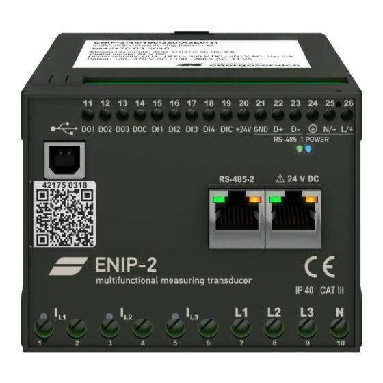
Operation Figure 5.3. RM6-KP dimensions (in millimeters) Connection 5.4.1 Wires Table 5.1 ENIP-2-…-Х1 ENIP-2-…-32 (Compact) Power supply 2.5 mm wires (AWG 14) 1.5 mm wires (AWG 16) Current input 4 mm wires (AWG 12) 4 mm wires (AWG 12) Voltage input 2.5 mm wires (AWG 14) Digital I/O... - Page 36 Operation Table 5.2 ENIP-2-XX/X-X-XX-X1 terminal symbol description I1 input I1 output I2 input I2 output I3 input I3 output U1 input U2 input U3 input UN input Table 5.3 ter- ENIP-2-XX/X-X-XX-41 ENIP-2-XX/X-X-XX-21 ENIP-2-XX/X-X-XX-11 minal symbol description symbol description symbol description Digital input 1 Digital output 1 Digital input 2...
- Page 37 Operation Figure 5.4 Analog inputs for ENIP-2 5.4.3 RJ-45 pinouts Digital interfaces pinouts for ENIP-2 given in Table 5.4 Table 5.4 Interface RJ-45 pinout RS-485-1, RS-485-3 5 – GND 7 – А (data+) 8 – B (data-) RS-485-2 with power 1,2 –power supply for ENMI (+24 V DC) 3,4 –power supply for ENMI (0 V) 5 –...
-
Page 38: Configuration Settings
Configuration settings Configuration settings ENIP-2 configuration setting implies setting up parameters for communication ports (RS- 485 and Ethernet), transmitted data, connection types, sync time, DIO and etc. Firmware update We are continuously working on adding on new features and updates for ENIP-2. That is why before using ENIP-2, please, visit our website to check the latest firmware and soft- ware (but it is not critical). -
Page 39: Configurator" Software
Figure 6.1. “EsBootloader” software main window «ES Configurator» software 6.2.1 Installation Software «ES Configurator” is used to configure IED ENIP-2. The latest version of config- uration software can be downloaded here: http://enip2.ru/software/esconfigurator.zip System requirements: Windows XP or newer and .NET Framework 4. - Page 40 Configuration settings Figure 6.2. “ES Configurator” software main window Configurator allows to create and save the settings without a necessity of connecting to the device. 6.2.2 Connection to the device Connect ENIP-2 to USB port, using USB type A to type B cable (fig. 6.3).
- Page 41 Configuration settings After running «ES Configurator», serial number of the device will be displayed in line “USB device”. Click button Identify to see information about ENIP-2. Figure 6.4. Information panel. - configuration window; - polling window; Reset view –disconnect from device;...
- Page 42 Configuration settings 6.2.3 Main settings Figure 6.5. Main settings Wiring 3 or 4 wiring voltage input Calculate Ib Calculate Ib for 2-wire current input Substitute low measurement Transmit low measurement value as zero Average current calculation method Arithmetic/RMS Averaging interval 200…2000 ms –...
- Page 43 Configuration settings 6.2.4 Time synchronization Figure 6.6. RTC synchronization settings Time zone -12…12 IEC 101 and 104 timestamp UTC or Local Synchronization Available protocol (see “Interface” field) for time sync: Ft3, IEC- 101/104, SNTP SNTP settings You can set primary and secondary (if need it) time servers. 6.2.5 Extension devices Figure 6.7.
- Page 44 Configuration settings Available extension devices for more digital inputs and outputs: ENMV-1, ENMV-2. Extension devices should be connected only via RS-485-2 communication port. Recom- mended baud rate is 115200 b/s. 6.2.6 Digital signals Figure 6.8. Digital signals settings List of available digital signals (DIO). Discrete output (built-in or external) Discrete input (built-in or external) Setpoint...
- Page 45 Configuration settings 6.2.7 RS-485 Figure 6.9. RS-485 setting List of available UART (RS-485) settings on the “RS-485” tab is below. Protocol IEC-101/Modbus/Ft3 Address Link address for IEC 101, slave address for Modbus and Ft3 Baudrate 600…115200 baud Parity Even/none/odd Stopbits 1 or 2 Response delay 0…25.5 ms...
- Page 46 Configuration settings List of available Modbus settings on the “Modbus” tab is below. Master mode Data transfer mode for ENMI. Interval The time interval between data sending values from all registers to ad- dress 0xFF. Measurement type Instant (averaging time of 50 ms) Fixed (data is updated once per second) “Discretes”...
- Page 47 Configuration settings 6.2.9 IEC-60870-101 Figure 6.12. Protocol IEC-60870-101 settings List of available IEC-60870-101/104 settings on the “IEC101/IEC104” tab is below. ENIP-2, manual, ENIP.411187.002. Rev. 11.2020...
- Page 48 Configuration settings ASDU address 1…65535 Allow command 103 Allow sync time Allow DO control Allow <45> command Allow direct control Allow <45> command without select Allow command 105 Allow reset counters Transmit buffered events Delay after connection before transmit log Measurement types Instant (averaging time of 50 ms) Fixed (data is updated once per second)
-
Page 49: Enip-2 Web-Interface
Configuration settings ENIP-2 web-interface For web-configuration of ENIP-2 you should connect the device to your local network and enter a browser following: http://XXX.XXX.XXX.XXX (XXX.XXX.XXX.XXX – IP-address ENIP-2) http://enip2nXXXXX (XXXXX – serial number of ENIP-2). Default login: admin Default password: admin. Use «ESFindIP»... -
Page 50: Reset To Default Settings
Configuration settings Reset to default settings For resetting configuration to default settings, use PC with “ES Bootloader” utility: − Connect ENIP-2 to COM-port or USB of PC, − Run "EsBootloader", − Set connection settings, − Click Connect, − Click “Default cfg”, −... -
Page 51: Maintenance
Maintenance Maintenance When performing the maintenance, follow the rules set in the manual. Maintenance is supposed to be performed by qualified personnel only. Do not open the housing during operation. Opening the ENIP-2 voids the warranty. ENIP-2 doesn’t need special maintenance operations. For cleaning use non-abrasive detergent or 70% ethanol-water solution. -
Page 52: Transportation, Packing And Storage
Transportation, packing and storage Transportation, packing and storage ENIP-2 is transported in any covered transport (train, car, airplane). Transport conditions temperature is –50…+70⁰С, relative humidity is 95 % at 30⁰С. Save ENIP-2 from impact during the transportation. ENIP-2 is delivered in packaging case. Package contents is according to page 33. Maximum weight of the device see in table 8.1. -
Page 53: Self-Diagnostics Of Enip-2
Self-diagnostics of ENIP-2 Self-diagnostics of ENIP-2 Errors codes of ENIP-2 Error code Description 0x0001 ADC failure/ no power supply 0x0002 No connection with Ethernet 0x0004 Clock error 0x0008 Low battery voltage 0x0010 Authorization error 0x0020 Internal communications error of ENIP-2 with 2 Ethernet ports 0x0040 Sync time error 0x0080... -
Page 54: Appendix A1. Wiring Diagrams Of Enip-2 Standard And Pmu
Appendix A1. Wiring diagrams of ENIP-2 Standard and PMU Appendix A1. Wiring diagrams of ENIP-2 Standard and PMU Figure А1.1. ENIP-2-41/100-… and ENIP-2-45/100-… for 4-wire three-phase grid (4-wire measurement mode must be activated) Figure А1.2. ENIP-2-41/100-… and ENIP-2-45/100-… for 3-wire three-phase grid (4-wire measurement mode must be activated) ENIP-2, manual, ENIP.411187.002. - Page 55 Appendix A1. Wiring diagrams of ENIP-2 Standard and PMU Figure А1.3. ENIP-2-41/100-… and ENIP-2-45/100-… Figure А1.4. ENIP-2-41/100-… and ENIP-2-45/100-… for 4-wire three-phase grid 220(380) V (4-wire meas- for 3-wire three-phase grid with two PT (3-wire urement mode must be activated) measurement mode must be activated) PT connection is Y PT connection is Δ...
- Page 56 Appendix A1. Wiring diagrams of ENIP-2 Standard and PMU Figure А1.6. ENIP-2-41/100-… and ENIP-2-45/100-… for 3-wire three-phase grid with three PT without neutral wire and two CT (3-wire measurement mode must be activated) Last diagram is not recommended! Power measurement errors may occur. ENIP-2, manual, ENIP.411187.002.
-
Page 57: Appendix А2. Wiring Diagrams Of Enip-2 Compact
Appendix А2. Wiring diagrams of ENIP-2 Compact Appendix А2. Wiring diagrams of ENIP-2 Compact Figure А2.1. ENIP-2-41/100-…-32 and ENIP-2-45/100-…-32 for 4-wire three-phase grid (4-wire measure- ment mode must be activated) Figure А2.2. ENIP-2-41/100-…-32 and ENIP-2-45/100-…-32 for 3-wire three-phase grid (4-wire measure- ment mode must be activated) ENIP-2, manual, ENIP.411187.002. - Page 58 Appendix А2. Wiring diagrams of ENIP-2 Compact Figure А2.3. ENIP-2-41/100-…-32 and ENIP-2-45/100- Figure А2.4. ENIP-2-41/100-…-32 and ENIP-2-45/100- …-32 for 4-wire three-phase grid 220(380) (4-wire …-32 for 4-wire three-phase grid with two PT (3-wire measurement mode must be activated) measurement mode must be activated) PT connection is Y PT connection is Δ...
- Page 59 Appendix А2. Wiring diagrams of ENIP-2 Compact Figure А2.6. ENIP-2-41/100-X-ХХ-32 and ENIP-2-45/100-X-ХХ-32 for current measuring in 1 phase ENIP-2, manual, ENIP.411187.002. Rev. 11.2020...
-
Page 60: Appendix A3. Wiring Diagrams For Extension Devices
Appendix A3. Wiring diagrams for extension devices Appendix A3. Wiring diagrams for extension devices Connection via RS-485: Master (IEC 60870-5- ENIP-2 RS-485-1 ENIP-2 RS-485-1 ENIP-2 RS-485-1 101/Modbus RTU) Master (IEC 60870-5- ENIP-2 ENIP-2 ENIP-2 101/Modbus RTU) RS-485-2, RS-485-3 RS-485-2, RS-485-3 RS-485-2, RS-485-3 Twisted pair Ground shield... - Page 61 Appendix A3. Wiring diagrams for extension devices ENMI «One ENMI – one ENIP-2» ENIP- - -Х1 RS-485-2, #2 RS-485-2, #2 (RJ-45 wth voltage 4В) (RJ-45 wth voltage 4В) RJ-45 RJ-45 1 / + 24 V 2 / +24V 3 / 0V 4 / 0V 5 / GND 7 / RS-485 data +...
- Page 62 Appendix A3. Wiring diagrams for extension devices «One ENMI – several ENIP-2» «several ENMI – one ENIP-2» Figure A3.3 – Connection of ENMI and ENIP-2 ENIP-2, manual, ENIP.411187.002. Rev. 11.2020...
- Page 63 Appendix A3. Wiring diagrams for extension devices Power supply ENIP-2-4X/X-220-XX-X1 100...265 V~ or 120...370 V L AC (phase) + DC N AC (neutral) - DC ENIP-2-4X/X-24-XX-X1 18...36 V + DC - DC ENIP-2-4X/X-220-XX-X3 100...265 V~ or 120...370 V L AC (phase) + DC N AC (neutral) - DC...
- Page 64 Appendix A3. Wiring diagrams for extension devices Sensor Inductive sensor could be used as a door-operated switch. The following is an example of wiring diagram of ENIP-2 and inductive sensor. Figure A3.4. Wiring diagram for ENIP-2 and inductive sensor ENIP-2, manual, ENIP.411187.002. Rev. 11.2020...
- Page 65 Appendix A3. Wiring diagrams for extension devices Digital I/O (including extension module ENMV) Figure A3.5. ENIP-2-…-X2 digital I/O connection example Figure A3.6. Available ENMV connections ENIP-2, manual, ENIP.411187.002. Rev. 11.2020...
-
Page 66: Appendix B. Enip-2: Modbus
Appendix B. ENIP-2: Modbus Appendix B. ENIP-2: Modbus About Modbus Modbus (Schneider Electric trademark) is a serial communication protocol. Full descrip- tion see on www.modbus.org. This protocol is used for data communication via RS-485 or Ethernet interfaces. Аddress Available slave addresses of ENIP-2 are from 01 to 254 (01-hFE). h00 and hFF are mul- ticast addresses. - Page 67 Appendix B. ENIP-2: Modbus Register addresses range is 0 to 59999. You can change the addresses of values using «ES Configurator». Values in registers are saved in integer and float formats. Available data type: • Integer ENIP-2 integer is little-endian order.
- Page 68 Appendix B. ENIP-2: Modbus Address Quantity of Value Type registers 0x13 Total Q short 0x14 unsigned short 0x15 unsigned short 0x16 unsigned short 0x17 Total S unsigned short Integer first harmonic 0x18 unsigned short 0x19 unsigned short 0x1A unsigned short 0x1B Average U1 unsigned short...
- Page 69 Appendix B. ENIP-2: Modbus Address Quantity of Value Type registers 0x46 WQ- reactive energy, reverse direction unsigned long 0x48 DIO – DI/DO status unsigned long 0x4A Time - timestamp UTC, seconds unsigned long 0x4C Time - timestamp UTC, milliseconds unsigned short 0x4D T –...
- Page 70 Appendix B. ENIP-2: Modbus Address Quantity of Value Type registers 0x86 float 0x88 float 0x8A Total S float Float first harmonic 0x8C float 0x8E float 0x90 float 0x92 Average U1 float 0x94 Uab1 float 0x96 Ubc1 float 0x98 Uca1 float 0x9A Average line-to-line U1 float...
- Page 71 Appendix B. ENIP-2: Modbus Address Quantity of Value Type registers 0xE6 0xE8 float ENIP-2-…-32 float value 0xDC float 0xDE float 0xE0 float 0xE2 0xE4 0xE6 0xE8 Discrete information Any DIO is configured independently. Available function for DIO are in the Table 3.3. Default configuration: Address Value...
- Page 72 Appendix B. ENIP-2: Modbus Address Value 0x1F DIO32 Here is an example of request with function code 01 if ENIP-2 has slave address 01, DIO requested from 2 to 13 Slave ad- Function Data address of the Number of coil dress code first coil...
- Page 73 Appendix C. ENIP-2: IEC 60870-5-101 and IEC 60870-5-104 Appendix C. ENIP-2: IEC 60870-5-101 and IEC 60870-5-104 Available ASDU Value ASDU Description M_SP_NA_1 Single-point information M_DP_NA_1 Double-point information Digital signals M_SP_TB_1 Single-point information with time tag CP56 M_DP_TB_1 Double-point information with time tag CP56 M_ME_NB_1 Measured value, scaled value Measured...
- Page 74 Appendix C. ENIP-2: IEC 60870-5-101 and IEC 60870-5-104 Quantum (for address Parameter ASDU type type 11,13,35,37) 11/13/35/36 Pquant, W Total P 11/13/35/36 Pquant, W 11/13/35/36 Qquant, var 11/13/35/36 Qquant, var 11/13/35/36 Qquant, var Total Q 11/13/35/36 Qquant, var 11/13/35/36 Squant, VA 11/13/35/36 Squant, VA 11/13/35/36...
- Page 75 Wquant, Вар/ч Files 40000 Event log, txt 50000 DI log txt * Addresses are marked by gray font is not available by default. You can activate them using «ES Con- figurator» Quantum value quantum Description I = 5 A I = 1 А...
- Page 76 Appendix C. ENIP-2: IEC 60870-5-101 and IEC 60870-5-104 - Function or ASDU is not used; - Function or ASDU is used as standardized (default); - Function or ASDU is used in reverse mode; - Function or ASDU is used in standard and reverse mode/ The possible selection (blank, X, R, or B) is specified for each specific Clause or parameter.
- Page 77 Appendix C. ENIP-2: IEC 60870-5-101 and IEC 60870-5-104 1200bit/s 38400 bit/s 38400bit/s 57600 bit/s 56000bit/s 115200 bit/s 64000bit/s IEC 60870-5-104 Unbalanced interchange cir- Unbalanced interchange Balanced interchange circuit X.24/X.27 cuit V.24/V.28 Standard circuit V.24/V.28 recom- mended if >1200 bit/s 100bit/s 2400bit/s...
- Page 78 Appendix C. ENIP-2: IEC 60870-5-101 and IEC 60870-5-104 Link transmission procedure Address field of the link Balanced transmission Unbalanced transmission Not present (balanced transmission Frame length only) One octet Maximum length L (control direction) Two octets Maximum length L (monitor direction) ...
- Page 79 Appendix C. ENIP-2: IEC 60870-5-101 and IEC 60870-5-104 5. Application layer Transmission mode for application data Mode 1 (least significant octet first), as defined in 4.10 of IEC 60870-5-4, is used exclusively in this companion standard. Common address of ASDU (system-specific parameter, all configurations that are used are to be marked with an X).
- Page 80 Appendix C. ENIP-2: IEC 60870-5-101 and IEC 60870-5-104 <1> M_SP_NA_1 Х Х <2> M_SP_TA_1 <3> M_DP_NA_1 Х Х <4> M_DP_TA_1 <5> M_ST_NA_1 <6> M_ST_TA_1 <7> M_BO_NA_1 <8> M_BO_TA_1 <9> M_ME_NA_1 <10> M_ME_TA_1 <11> M_ME_NB_1 Х Х Х <12> M_ME_TB_1 <13> M_ME_NC_1 Х...
- Page 81 Appendix C. ENIP-2: IEC 60870-5-101 and IEC 60870-5-104 <121> F_SR_NA_1 <122> F_SC_NA_1 <123> F_LS_NA_1 <124> F_AF_NA_1 <125> F_CG_NA_1 <126> F_DR_TA_1 IEC 60870-5-101 Cause of transmission Type identification <1> M_SP_NA_1 Х Х <2> M_SP_TA_1 <3> M_DP_NA_1 Х Х <4> M_DP_TA_1 <5> M_ST_NA_1 <6>...
- Page 82 Appendix C. ENIP-2: IEC 60870-5-101 and IEC 60870-5-104 <103> C_CS_NA_1 <104> C_TS_NA_1 <105> C_RP_NA_1 <106> C_CD_NA_1 <110> P_ME_NA_1 <111> P_ME_NB_1 <112> P_ME_NC_1 <113> P_AC_NA_1 <120> F_FR_NA_1 <121> F_SR_NA_1 <122> F_SC_NA_1 <123> F_LS_NA_1 <124> F_AF_NA_1 <125> F_CG_NA_1 <126> F_DR_TA_1 6. Basic application functions Station initialization ...
- Page 83 Appendix C. ENIP-2: IEC 60870-5-101 and IEC 60870-5-104 Bitstring of 32 bit M_BO_NA_1, M_BO_TA_1, M_BO_TB_1 (if defined for a specific pro- ject, see 7.2.1.1) Measured value, normalized value M_ME_NA_1, M_ME_TA_1, M_ME_ND_1, M_ME_TD_1 Measured value, scaled value M_ME_NB_1, M_ME_TB_1, M_ME_TE_1 ...
- Page 84 Appendix C. ENIP-2: IEC 60870-5-101 and IEC 60870-5-104 Mode B: local freeze with counter interrogation Mode C: freeze and transmit by counter interrogation commands Mode D: freeze by counter-interrogation command, frozen values reported spontane- ously Counter read ...
- Page 85 Appendix C. ENIP-2: IEC 60870-5-101 and IEC 60870-5-104 Transmission of sequences of recorded analogue values File transfer in control direction Transparent file Background scan Background scan For IEC 60870-5-104 only: Definition of time outs Default Selected Parameter Remarks value value 30 s...
- Page 86 Appendix D. ENIP-2: IEC 61850 Appendix D. ENIP-2: IEC 61850 This conformance statement of IEC 61850 refers to ENIP-2 with firmware 2.0.0.6 new. Additional conformance statement of ENIP-2 IEC 61850 available at links: – • MICS Model Implementation Conformance Statement •...
- Page 87 Appendix D. ENIP-2: IEC 61850 Client/ Server/ Value/ subscriber publisher comments If Server side (B11) supported Logical device ● Logical node ● Data ● Data set ● Substitution Setting group control Reporting Buffered report control ● M7-1 sequence-number ● M7-2 report-time-stamp ●...
- Page 88 Appendix D. ENIP-2: IEC 61850 Client/ Server/ Value/ subscriber publisher comments Time File Transfer Table E.1.3 – ACSI service conformance statement Services Client/ Server/ Comments TP/MC subscriber publisher Server (Clause 6) Server Directory ● Application association (Clause 7) Associate ● Abort ●...
- Page 89 Appendix D. ENIP-2: IEC 61850 Services Client/ Server/ Comments TP/MC subscriber publisher Reporting (Clause 14) Buffered report control block (BRCB) Report ● S24-1 data-change (dchg) ● S24-2 qchg-change (qchg) ● S24-3 data-update (dupd) ● GetBRCBValues ● SetBRCBValues ● Unbuffered report control block (URCB) Report ●...
- Page 90 Appendix D. ENIP-2: IEC 61850 Services Client/ Server/ Comments TP/MC subscriber publisher Unicast SVC SendUSVMessage GetUSVCBValues SetUSVCBValues Control (17.5.1) Select SelectWithValue ● Cancel ● Operate ● CommandTermination ● TimeActivated-Operate File transfer (Clause 20) GetFile SetFile DeleteFile GetFileAttributeValues Time (Clause 18) Time resolution of internal clock 1 ms Time accuracy of internal clock...
- Page 91 Appendix D. ENIP-2: IEC 61850 Mandatory tissues Table D.1.4 Applied/Yes/ Part Tissue # Technical Issue Subject Not applied GetNameList with empty response? Improper Error Response for GetDataSetValues GetNameList error handling Not applied Control negative response Not applied FIle directories Not applied Definition of APC Not applied Point def xVal, not cVal...
- Page 92 Appendix D. ENIP-2: IEC 61850 (part of #453) Reporting with BufTm=0 (part of Write Configuration attribute of BRCBs #453) (part of #453) Reporting and BufOvl Enabling of an incomplet GoCB (part of #453) Clearing of Bufovfl (part of #453) URCB class and report (part of BRCB TimeOfEntry has two definitions #453)
- Page 93 Appendix E. ENIP-2: SNMP Appendix E. ENIP-2: SNMP ENIP-2 can transmit the following Management Information Base (MIB) (*.mib file for ENIP-2 is here): Community: all; public MIB-object Description Value Intelligent elec- SysDescr.0 Device name tronic device ENIP-2 (v2) XX hours, XX SysUpTime.0 Time after start minutes, XX...
- Page 94 Appendix E. ENIP-2: SNMP dio4 Status DIO4 On/off dio5 Status DIO5 On/off dio6 Status DIO6 On/off dio7 Status DIO7 On/off dio8 Status DIO8 On/off dio9 Status DIO9 On/off dio10 Status DIO10 On/off dio11 Status DIO11 On/off dio12 Status DIO12 On/off dio13 Status DIO13 On/off...
- Page 95 Appendix E. ENIP-2: SNMP voltageH1PhaseAverage Average U1 Value voltageH1LineAB Uab1 Value voltageH1LineBC Ubc1 Value voltageH1LineCA Uca1 Value voltageH1LineAverage Average line-to-line U1 Value currentH1PhaseA Value currentH1PhaseB Value currentH1PhaseC Value currentH1PhaseAverage Average I1 Value powerH1ActiveA Value powerH1ActiveB Value powerH1ActiveC Value powerH1ActiveTotal Total P1 Value powerH1ReactiveA Value...
Need help?
Do you have a question about the ENIP-2-X1 Series and is the answer not in the manual?
Questions and answers