
Related Manuals for Heatcraft Mohave

Summary of Contents for Heatcraft Mohave
- Page 1 Mohave Hot Gas Defrost Installation & Operation H-IM-HGD0 FEBRUARY 2021 Part Number 25007401 Replaces June 2017 Installation, Start-Up, Operation and Troubleshooting with Wiring Diagrams...
-
Page 2: Table Of Contents
Refrigeration Oils ..................57 Troubleshooting .................58-60 Preventive Maintenance ..................61-62 InterLink Service Parts ..................63 Service Record ..................64 Factory Default Settings ...................65-68 Mohave Control Board Comparison................ 69 Electronic Pressure Regulator Comparison .............. 70 Modbus Definitions ..................71-74 © 2021 Heatcraft Refrigeration Products LLC... -
Page 3: Controller Quick Reference Guide
Controller Quick Reference Guide The Mohave ™ Hot Gas Controller is located inside the condensing unit electrical panel. The Service Switch is adjacent to the controller on the side of the enclosure. Reset Program Monitor Time Review Enter Control Buttons... - Page 4 Controller Quick Reference Guide Program Review Menu FACTORY DISPLAY DESCRIPTION DEFAULT Set the Time of Day clock hour value None CLKH Set the Time of Day clock minute value None CLKM Set Fahrenheit or Celsius temperature units (°F or °C) °F °F °C Set Time display method (12 hr.
- Page 5 Controller Quick Reference Guide Forced Output Menu DISPLAY DESCRIPTION Evaporator Fan Contactor EVPF Liquid Line Solenoid LIQS Evaporator Pan Heater EVPH Condenser Fan 4 Contactor FAN4 Condenser Fan 3 Contactor FAN3 Condenser Fan 2 Contactor FAN2 Condenser Fan 1 Contactor FAN1 Compressor Contactor COMP...
-
Page 6: General Safety Information
Products specified minimum clearances. transportation of the motor compressor to and from the wholesaler. The replacement Devices not provided by Heatcraft shall not be connected to the motor compressor shall be identical to the model of the motor compressor being Mohave controller without written factory approval replaced. -
Page 7: System And Components
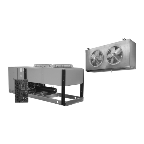
System and Components Condensing Unit (Vertical Air Discharge Design) Standard Features: Evaporators • Electronic Hot Gas Defrost Controller includes Defrost Initiation and (Medium Profile & High Profile Unit Coolers) Termination Control, Pressure Fan Cycling for Head Pressure Control, Ambient Fan Cycling Option, Anti-Short Cycling Protection, and Low Pressure Control •... -
Page 8: Unit Cooler Installation
Unit Cooler Installation Unit Cooler Installation Most evaporators can be mounted with rod hangers, lag screws, or bolts. Use 5/16" top and the ceiling with an NSF listed sealant and ends of open hanger channels must bolt and washers or rod for up to 250 pounds, 3/8" for up to 600 pounds and be sealed to prevent accumulation of foreign matter. -
Page 9: Placement
Unit Cooler Installation & Condensate Lines Unit Coolers (continued) Recommended Unit Cooler Placement Traps on low temperature units must be outside of refrigerated enclosures. Traps Some general rules for evaporator placement which must be followed are: subject to freezing temperatures must be wrapped with heat tape and insulated. The air pattern must cover the entire room NEVER locate evaporators over doors Location of aisles, racks, etc. -
Page 10: Condensing Unit Installation
Condensing Unit Installation Space & Location Requirements for Air Cooled Condensing Units and Remote Condensers The most important consideration which must be taken into account when deciding Another consideration which must be taken is that the unit should be mounted away upon the location of air-cooled equipment is the provision for a supply of ambient from noise sensitive spaces and must have adequate support to avoid vibration air to the condenser, and removal of heated air from the condensing unit or remote... -
Page 11: Rigging
Condensing Unit Installation Condensing Unit Rigging and Mounting Rigging holes are provided on all units. Caution should be exercised when moving Spring Mounted Compressor these units. To prevent damage to the unit housing during rigging, cables or chains Compressors are secured rigidly to make sure there is no transit damage. Before used must be held apart by spacer bars. -
Page 12: Field Piping Guidelines
Refrigerant Pipe Support Normally, any straight run of tubing must be supported in at least two locations The system as supplied by Heatcraft Refrigeration Products, was near each end of the run. Long runs require additional supports. The refrigerant thoroughly cleaned and dehydrated at the factory. Foreign matter may enter the lines should be supported and fastened properly. - Page 13 Piping The following are examples of proper piping layout for typical system configurations...
- Page 14 Piping...
- Page 15 Piping Unit Cooler Piping Pipe size example: NOTE: This is a line sizing example. Use diagrams on page Given: -10°F Freezer with one system having (2) evaporators 13-14 for piping orientation. • One condensing unit rated at 24,000 BTUH’s @ -20°F SST R404A refrigerant. •...
- Page 16 Line Sizing Table 1. Recommended Line Sizes for R-407* SUCTION LINE SIZE SUCTION TEMPERATURE ˚F ˚F ˚F System Equivalent Lengths Equivalent Lengths Equivalent Lengths Capacity 100' 150' 200' 100' 150' 200' 100' 150' 200' 1,000 3,000 4,000 6,000 9,000 12,000 15,000 18,000 1 1/8 1 1/8...
- Page 17 Line Sizing Table 1A. Recommended Line Sizes for R-407 (continued)* LIQUID LINE SIZE Receiver to Expansion Valve Expansion Valve 100' 150' 200' 1,000 3,000 4,000 6,000 9,000 12,000 15,000 18,000 24,000 30,000 36,000 42,000 48,000 54,000 60,000 66,000 72,000 78,000 84,000 90,000 120,000...
- Page 18 Line Sizing Table 2. Recommended Line Sizes for R-448A/R-449A SUCTION LINE SIZE SUCTION TEMPERATURE System Capacity ˚F ˚F ˚F BTU/H Equivalent Lengths Equivalent Lengths Equivalent Lengths 100' 150' 200' 100' 150' 200' 100' 150' 200' 1,000 3,000 4,000 6,000 9,000 1 1/8 12,000 1 1/8...
- Page 19 Line Sizing Table 2. Recommended Line Sizes for R-448A/R-449A (continued)* SUCTION LINE SIZE SUCTION TEMPERATURE System ˚F ˚F ˚F Capacity Equivalent Lengths Equivalent Lengths Equivalent Lengths BTU/H 100' 150' 200' 100' 150' 200' 100' 150' 200' 1,000 3,000 4,000 6,000 1 1/8 9,000 1 1/8 1 1/8...
- Page 20 Line Sizing Table 2A. Recommended Line Sizes for R-448A/R-449A LIQUID LINE SIZE Receiver to Expansion Valve Expansion Valve 100' 150' 200' 1,000 3,000 4,000 6,000 9,000 12,000 15,000 18,000 24,000 30,000 36,000 42,000 48,000 54,000 60,000 66,000 72,000 78,000 84,000 90,000 120,000 150,000...
- Page 21 Line Sizing Table 3. Recommended Line Sizes for R-404A and R-507 * SUCTION LINE SIZE SYSTEM SUCTION TEMPERATURE CAPACITY +40˚F +10˚F 0˚F +20˚F BTU/H Equivalent Lengths Equivalent Lengths Equivalent Lengths Equivalent 100' 150' 200' 100' 150' 200' 100' 150' 200' 1,000 3,000 4,000...
- Page 22 Line Sizing Table 3A. Recommended Line Sizes for R-404A and R-507 (continued) * SUCTION LINE SIZE LIQUID LINE SIZE SUCTION TEMPERATURE Receiver to -20˚F -30˚F -40˚F Expansion Valve SYSTEM Lengths Equivalent Lengths Equivalent Lengths Equivalent Lengths CAPACITY 100' 150' 200' 100' 150' 200'...
- Page 23 Line Sizing Table 4. Weight of Refrigerants in Copper Lines During Operation (Pounds per 100 Lineal feet of type"L" tubing) Line Size Suction Line at Suction Temperature O.D. Liquid -40˚F -20˚F 0˚F +20˚F +40˚F in Inches Refrigerant Line R-507/R-404A R-407 R-448A/R-449A R-507/R-404A R-407...
- Page 24 Line Sizing Table 5. Pressure Loss of Liquid Refrigerants in Liquid Line Risers (Expressed in Pressure Drop, PSIG, and Subcooling Loss, ˚F). Liquid Line Rise in Feet 100' PSIG ˚F PSIG ˚F PSIG ˚F PSIG ˚F PSIG ˚F PSIG ˚F PSIG ˚F PSIG...
-
Page 25: Optional Controls
Optional Controls Head Pressure Control CAUTION: For Ambient Fan Cycling; Under no circumstance should all condenser motors be allowed to cycle off A. Dual Valve System on one control. At least one motor shall be wired to The system employs an ORI (open on rise of inlet pressure) valve and an ORD ( open operate at all times. -
Page 26: Operation
Optional Controls E. Copeland Demand Cooling for Discus L6 Models Demand Cooling System Design Energy efficiency regulations drive continuous change in the availability of refrigerants When Demand Cooling operates, it “diverts” refrigeration capacity in the form of to the marketplace. With the introduction of R-22 as a replacement for R-502 injected saturated refrigerant from the evaporator to the compressor. -
Page 27: System Wiring
The temperature and pressure sensors Mohave Hot Gas System Controller Battery Back-Up - The control board has a located on the condensing unit are pre-connected to the control board at the factory. - Page 28 Wiring Diagram (24V) (Standard Independent Evaporator Power Supply) CONTROL BOARD (Field supplied, not used when auxiliary temperature sensor is field installed and activated to control room temperature)
- Page 29 Wiring Diagram (24V) (Standard Independent Evaporator Power Supply) CONTROL BOARD (Field supplied, not used when auxiliary temperature sensor is field installed and activated to control room temperature)
- Page 30 Wiring Diagram Typical Evaporator Wiring (Electric Drain Pan Heater) (Standard Independent Evaporator Power Supply) 208-230V / 3 / 60 HZ Heatcraft Refrigeration -OR-575V / 3 / 60HZ Products LLC FOR SINGLE PHASE EVAP FAN EVAP EVAP T-STAT LIQ. LINE SEE NOTE # 2 DEFR.
- Page 31 Wiring Diagram Typical Evaporator Wiring (Hot Gas Drain Pan) (Standard Independent Evaporator Power Supply) Heatcraft, Inc. 208-230V / 3 / 60 HZ 460V / 3 / 60HZ 575V / 3 / 60HZ FOR SINGLE PHASE SEE NOTE #2 T1 T2...
- Page 32 Wiring Diagram Typical Evaporator Wiring (Electric Drain Pan Heater) (Optional Evaporator Powered Off Condensing Unit) Heatcraft Refrigeration Products LLC CONDENSING UNIT EVAP EVAP EVAP FAN LIQ. LINE T-STAT DEFR. HTR DEFR.TEMP SOL. 24 VAC 18 GA. MIN. HEATER CONTACTOR CONTACTOR...
- Page 33 Wiring Diagram Typical Evaporator Wiring (Hot Gas Drain Pan) (Optional Evaporator Powered Off Condensing Unit) Heatcraft, Inc. EVAP FAN EVAP LIQ. LINE T-STAT DEFR.TEMP SOL. CONDENSING 24 VAC UNIT 18 GA. MIN. CONTACTOR * ROOM THERMOSTAT ( FIELD SUPPLIED )
- Page 34 Wiring Diagram (Standard Independent Evaporator Power Supply) 208-230V/60Hz/3Ø - CONDENSING UNIT - UNIT WIRING CONTACTOR C2 COMPRESSOR POWER BLOCK CONTACTOR C1 SHEET 2 10 11 YELLOW BLUE CRANKCASE HEATER SERVICE MATE COMP AUX1 AUX2 CMOD HEADER/COMPRESSOR END LEGEND C ------- CONTACTOR SHEET 1 OF 2 Model #: BDV2702L6C...
- Page 35 Wiring Diagram (Standard Independent Evaporator Power Supply) 208-230V/60HZ/3Ø - CONDENSING UNIT - CONTROL BOARD WIRING SHEET 1 230V PRESSURE REGULATOR 3-Way Sol. Alarm 3-Way Sol. SERVICE SW. Defrost Sol Defrost Sol SAFETY CKT. Suction Sol Suction Sol BLUE Bypass Valve SUCTION TEMP CU Suct Temp Bypass Valve...
- Page 36 Wiring Diagram (Standard Independent Evaporator Power Supply) 460V/60Hz/3Ø - CONDENSING UNIT - UNIT WIRING COMPRESSOR POWER BLOCK CONTACTOR C1 460V H4 TRANSFORMER 230V SHEET 2 13 14 YELLOW BLUE CRANKCASE HEATER SERVICE MATE COMP AUX1 AUX2 CMOD HEADER/COMPRESSOR END HEADER/COMPRESSOR END C ------ CB ----- CM ----...
- Page 37 Wiring Diagram (Standard Independent Evaporator Power Supply) 460V/60HZ/3Ø - CONDENSING UNIT - CONTROL BOARD WIRING SHEET 1 230V PRESSURE REGULATOR 3-Way Sol. Alarm 3-Way Sol. SERVICE SW. Defrost Sol Defrost Sol SAFETY CKT. Suction Sol Suction Sol BLUE Bypass Valve CU Suct Temp SUCTION TEMP Bypass Valve...
- Page 38 Wiring Diagram (Standard Independent Evaporator Power Supply with VFD Condenser Fans)
- Page 39 Wiring Diagram (Standard Independent Evaporator Power Supply with VFD Condenser Fans)
-
Page 40: Hot Gas Unit Cooler Typical Factory Piping
Hot Gas Unit Cooler Typical Factory Piping Note: Control contactors mount under a cover on front of unit (not shown) Electrical Connections (this side) Flow Suction Connection Liquid Connection Liquid Solenoid Valve Thermostatic Expansion Valve Check Valves Check Valve Hot Gas Suction rain Pan P-Trap... -
Page 41: Hot Gas Condensing Unit Typical Factory Piping
Hot Gas Condensing Unit Typical Factory Piping COMPRESSOR SUCTION ACCUMULATOR DEFROST DEFROST SOLENOID VALVE SOLENOID (NC) (NC) SUCTION PRESSURE SENSOR LOCATION REDUNDANT LOW PRESSURE SWITCH LOCATION 3-WAY VALVE (NO BLEED PORT) LIQUID PRESSURE SENSOR LOCATION BASE SUCTION STOP SUCTION VALVE SOLENOID VALVE SOLENOID (NC) -
Page 42: Refrigeration Operation
Refrigeration Operation During refrigeration operation, the hot gas controller monitors liquid pressure The refrigeration operation of the Mohave Hot Gas System is very similar to a to determine if each fan should be ON or OFF. standard refrigeration system. An external thermostat is connected to the hot... - Page 43 Refrigeration Operation To pump down, the Liquid Line Solenoid(s) is deactivated and the compressor runs until the pressure measured at the suction accumulator falls below the pre-programmed cut out pressure value, or two minutes has elapsed. The compressor is then turned off until the start of the next cooling cycle.
-
Page 44: Defrost Operation
Defrost Operation Defrost Operation Defrost Timing/Schedule Programming The hot gas controller can be programmed with up to 12 defrost start times. Termination of defrost is accomplished by either both evaporators reaching The Program Review menu section describes the process to program or their target termination temps, or the liquid pressure measured between the delete a valid start time. - Page 45 Defrost Operation Hot Gas Defrost Cycle Diagrams Black = Piping Inactive Gray = Piping Active...
- Page 46 Defrost Operation Hot Gas Defrost Cycle Diagrams Black = Piping Inactive Gray = Piping Active...
- Page 47 Defrost Operation Defrost Termination Parameters The hot gas controller uses a combination of temperature, pressure and time values to make the decision to end the defrost cycle. The Defrost Failsafe Time is used at all times to limit the length of defrost. At cool ambient temperatures, the controller checks both the temperature and pressure of the defrosting evaporator(s) before making a termination decision.
-
Page 48: Evacuation & Leak Detection
Evacuation & Leak Detection Leak Testing Evacuation & Leak Detection After all lines are connected, the entire system must be leak tested. The complete Due to the smaller molecule size of HFC’s, they will tend to leak more readily than system should be pressurized to not more than 150 psig with refrigerant and CFC’s. -
Page 49: Check Out & Start-Up
Start-Up Operation and Program Review Check Out and Start Up Start-Up Operation - Initial Power On After the installation has been completed, the following points should be covered before At the initial application of power to the system, the compressor and the evaporator the system is placed in operation: fans will be in a 2-minute hold-off cycle and will not start immediately. -
Page 50: Program Review
Program Review Program Review Use the Program Review button to select these (Items Available when in Mode) Expert items: CLKH ..Set the Time of Day clock hour value CLKM ..Set the Time of Day clock minute value °F°C ..Set Fahrenheit/Celsius temperature units (°F/°C) Clock Hour setting –... - Page 51 – This parameter is the box temperature, or room equalization process and the ‘post-defrost’ drain time. The selection range is 1 minute to 10 temperature, set point that the Mohave board will control to using the auxiliary temperature minutes. Default: 2 minutes.
-
Page 52: Monitoring & Reviewing Operation Values
Monitoring and Reviewing Operation Values Forced Output Items Reviewing Operation Values These items are displayed as the blue knob is turned in a clockwise direction. Turning the knob The Monitor button is used to examine and review the current operating conditions of the counter clockwise reverses the order. -
Page 53: Error And Alarm Details
Error and Alarm Details Alarms Mode Safety Circuit Interruption - Alr3 Alr1 Persistent input sensor/transducer failure If the safety circuit input signal is broken during normal refrigeration or defrost, Combined Err4 and Err8, system off Alr2 Err9 is displayed. This failure is caused when one of the components connected to the Service Mate such as the oil pressure switch or the high pressure switch Alr3... -
Page 54: Refrigerant Charging
Refrigerant Charging Charge Quantity and Condenser Fan Control Refrigerant Charging Instructions The method of head pressure control affects refrigerant charge and the staging of Install a liquid line drier in the refrigerant supply line between the service the condenser fans. The system should have the minimum charge necessary to allow gauge and the liquid service port of the receiver. - Page 55 Refrigerant Charging Condenser Flooding Charge, Lbs (90%) RECEIVER -5F SST -25F SST -5F SST -25F SST CAPACITY Lbs -20F AMB -20F AMB 20F AMB 20F AMB MODEL/ REFRIG SIZE L6 (R404A/R507) 0602, 0752 L6 (R404A/R507) 0902, 1002, 1202 L6 (R404A/R507) 1502 L6 (R404A/R507) 2202...
-
Page 56: Operational Check Out
System Balancing - Compressor Superheat To properly determine the superheat of the evaporator, the following procedure is the method Heatcraft recommends: IMPORTANT: In order to obtain the maximum capacity from a Measure the temperature of the suction line at the system, and to ensure trouble-free operation, it is necessary to balance each and every system. -
Page 57: Refrigeration Oils
Refrigeration Oils Polyol Ester Lubricants Hygroscopicity Polyol Ester Lubricants Ester lubricants (POE) have the characteristic of quickly absorbing moisture from The Mobil EAL ARCTIC 22 CC is the preferred Polyol ester due to unique additives the ambient surroundings. This is shown graphically in Figure 7 where it can be included in this lubricant. -
Page 58: Troubleshooting
Troubleshooting Hot Gas Controller Troubleshooting Chart... - Page 59 Troubleshooting General Evaporator Troubleshooting Chart SYMPTOMS POSSIBLE CAUSES POSSIBLE CORRECTIVE STEPS Fan(s) will not operate 1. Main switch open 1. Close switch 2. Blown fuses 2. Replace fuses. Check for short circuits or overload conditions 3. Defective motor 3. Replace motor 4.
- Page 60 4. Correct piping. Compressor thermal protector switch open 1. Operating beyond design conditions. 1. Add components to bring conditions within acceptable limits (Consult Heatcraft) 2. Discharge valve partially shut. 2. Open valve. 3. Blown valve plate gasket. 3. Replace gasket.
-
Page 61: Preventive Maintenance
Preventive Maintenance Unit Coolers Air Cooled Condensing Units At every six month interval, or sooner if local conditions cause clogging or fouling of air passages through the finned surface, the following items should be checked. Quarterly 1) Visually inspect unit 1) Visually inspect unit •... - Page 62 Preventive Maintenance Semi-Annually (cont.) Annually 5) Inspect electrical wiring and components 7) In addition to quarterly and semiannual maintenance checks, submit an oil sample for analysis • Verify that all electrical and ground connections are secure, tighten as required. • Look for high concentrations of acid or moisture. Change oil and driers until test results read normal.
-
Page 63: Interlink Service Parts
Hot Gas Defrost System Service Parts Whenever possible, replacement parts are to be obtained from a local wholesaler authorized to sell one of Heatcraft Refrigeration Products’ brands. Replacement parts which are covered under the terms of the warranty statement on page 6 of this manual, will be reimbursed for total part cost only. The original invoice from the parts supplier must accompany all warranty claims for replacement part reimbursement. -
Page 64: Service Record
Service Record A permanent data sheet should be prepared on each refrigeration system at an If another firm is to handle service and maintenance, additional copies should be installation, with a copy for the owner and the original for the installing contractor's files. prepared as necessary. -
Page 65: Factory Default Settings
Factory Default Settings Fan Cycle Settings (Liquid Pressure, PRES), psig CAREL ALCO DFT 1 MODEL REFRIG SIZE Fan 1 Fan 2 Fan 3 Fan 4 Fan 1 Fan 2 Fan 3 Fan 4 DFT 2 DEFP DEFT EQUT LPSH LPSL FZET FZTM °F... - Page 66 Factory Default Settings Fan Cycle Settings (Liquid Pressure, PRES) , psig CAREL ALCO DFT 1 MODEL REFRIG SIZE Fan 1 Fan 2 Fan 3 Fan 4 Fan 1 Fan 2 Fan 3 Fan 4 DFT 2 DEFP DEFT EQUT LPSH LPSL FZET FZTM...
- Page 67 Factory Default Settings Fan Cycle Settings (Liquid Pressure, PRES) , psig CAREL ALCO DFT 1 MODEL REFRIG SIZE Fan 1 Fan 2 Fan 3 Fan 4 Fan 1 Fan 2 Fan 3 Fan 4 DFT 2 DEFP DEFT EQUT LPSH LPSL FZET FZTM...
- Page 68 FZET- Evap. Refreeze Temp FZTM- Evap. Refreeze Max. Time **Drawing 29326701 indicates, " Valve has been qualified by Heatcraft for a minimum room temperature of -30C (-22F) and a minimum refrigerant temperature of -35C (-31F) ***Suction Pressure Transducer, 28911202, (0-300 psia)
-
Page 69: Mohave Control Board Comparison
Mohave Control Board Comparison FIRST GENERATION HRP# 28910301 SECOND GENERATION HRP# 28910302 No Terminal Block Note: Screws must be tight to provide grounding. Redundant Low Pressure Switch Terminals ( REMOTE DEFR & C Redundant Low Pressure Switch Terminals ( SEPARATE TERMINAL BLOCK... -
Page 70: Electronic Pressure Regulator Comparison
Electronic Pressure Regulator Comparison SEE PAGE 39 OF INSTALLATION MANUAL FOR LOCATION OF PRESSURE REGULATOR IN CONDENSING UNIT. DETERMINE THE MANUFACTURER BASED UPON THIS PICTORIAL... -
Page 71: Modbus Definitions
Heatcraft Mohave Control Modbus Definitions Heatcraft Mohave Control Rev. 17 10/4/2016 ModBus Definitions NOTE: For this device, ModBus message frames must be no larger that 256 bytes NOTE: For ModBus commands, temperatures are always degrees F, pressures are always psia, and times are always 24-hour HHMM... - Page 72 Mohave Hot Gas Control Modbus Definitions Suction Pressure (0 to 300 psia), displayed as 30" Hg to 285 psig Word SucP Liquid Pressure (0 to 500 psia), displayed as 30" Hg to 485 psig Word LIQP Evap 1 Defrost Temp (-55 to +125 degrees F)
- Page 73 Heatcraft Mohave Control Modbus Definitions Last elapsed defrost time (minutes) Word DFTM Compressor cycles since midnight (0 to 255) Word CCYC Run time since midnight (0000 to 2359 HHMM) Word RnTM Elapsed time since last defrost (00000 to 25559 HHHMM)
- Page 74 67 to 7999 Remote Control (0xAA55=activate, 0xFF00=deactivate) Word 8000 NOTE: The Write Remote Control command with a data value of 'activate' is ignored unless the Mohave Control is in "Off" or "Service" modes Diagnostic - CMD 0x08 (Read/Write) Sub-Function Restart communications...
- Page 75 Notes...
- Page 76 Since product improvement is a continuing effort, we reserve the right to make changes in specifications without notice. Heatcraft Refrigeration Products LLC 2175 West Park Place Blvd. • Stone Mountain, GA 30087 770-465-5600 • Fax: 770-465-5990 • www.heatcraftrpd.com H-IM-HGD0221 | Version 002...
Need help?
Do you have a question about the Mohave and is the answer not in the manual?
Questions and answers