Table of Contents
Advertisement
Quick Links
Advertisement
Table of Contents

Summary of Contents for Milesight Agricultural Kit
- Page 1 Agricultural Kit Quick Guide Milesight IoT...
- Page 2 Safety Precautions Milesight will not shoulder responsibility for any loss or damage resulting from not following the instructions of this operating guide. The kit must not be remodeled in any way. EM300/EM500 are not intended to be used as reference sensors, and Milesight will ...
-
Page 3: Table Of Contents
5. EM300/EM500 Configuration....................11 5.1 EM500 Assembly......................11 5.2 Software Configuration....................12 5.2.1 Mobile APP Configuration...................12 5.2.2 Windows Software Configuration..............13 6. Milesight IoT Cloud Configuration...................15 7. Hardware Installation........................ 16 7.1 UG65 Installation......................16 7.2 UC1114 Installation......................17 7.3 EM300 Installation......................18 7.4 EM500 Installation...................... -
Page 4: Overview
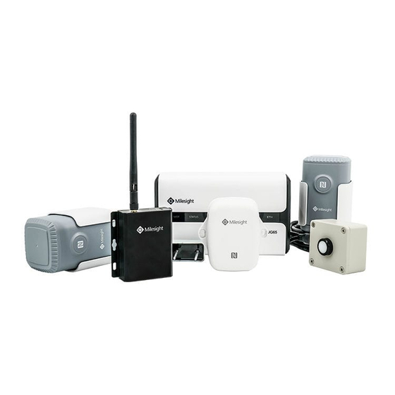
PoC about LoRaWAN ® network establishment and remote monitoring for the agricultural environment. More information about every product is available on Milesight IoT website. 2. Preparation 2.1 Packing List 1 × DC Jack Power 1 × Mounting 1 ×... -
Page 5: Software Preparation
Mobile APP for NFC EM300/EM500 Apple Store or Google Toolbox configuration. sensors Play (APP ver.) Milesight IoT Add and manage the Milesight IoT Apple Store or Google Cloud LoRaWAN ® nodes on the Cloud Play (APP ver.) Milesight IoT Cloud. -
Page 6: Ug65 Gateway Configuration
3. UG65 Gateway Configuration 3.1 Fitting Installation Step 1: Insert the SIM card into the device according to the direction icon on the device. If you need to take out the SIM card, press into the SIM card and it will pop up automatically. -
Page 7: Network Connection
your Internet browser to log in the web GUI. Wired Mode: Connect Ethernet port of UG6x to your computer and configure the IP address of computer manually, then type 192.168.23.150 to your browser to log in the web GUI. Here are steps of configuring computer IP address manually based on Windows 10 system. -
Page 8: Configure The Cellular Connection
3.3.2 Configure the Cellular Connection Step 1: Go to “Network” → “Interface” → “Cellular” → “Cellular Setting” page to enable cellular settings and fill in SIM card information like APN or PIN code. -
Page 9: Lorawan Configuration
3.4 LoRaWAN Configuration Step 1: Go to “Packet Forwarder” → “General” page to enable the “Milesight” type server. Step 2: Go to “Network Server” → “General” page to enable the network server and Milesight IoT Cloud mode. -
Page 10: Uc1114 Configuration
4. UC1114 Configuration Step 1: Rotate the antenna into the antenna connector accordingly. The external LoRa antenna should be installed vertically always on a site with a good signal. Step 2: Connect the terminal devices to digital input or reply output of the UC1114. Step 3: Power on the UC1114 via terminal block(VIN, GND). -
Page 11: Em300/Em500 Configuration
5. EM300/EM500 Configuration 5.1 EM500 Assembly Follow the steps below to connect light and soil sensor cable to EM500 transceiver if they are separated. Step 1: Take off the mounting bracket, remove the cap, rubber seal and the screws on the bottom of the device, and then take off the enclosure cover. -
Page 12: Software Configuration
5.2 Software Configuration EM300/EM500 sensors can be configured by one of the following ways: Mobile APP (NFC); Windows Software (Type-C Port). In order to ensure the security of the EM300/EM500 sensors, please type correct password to verity when changing the settings. Default password: 123456. 5.2.1 Mobile APP Configuration Step 1: Enable NFC on the smartphone and open the APP “Toolbox”, then attach the... -
Page 13: Windows Software Configuration
Step 4: Configure other parameters like reporting interval and alarms. 5.2.2 Windows Software Configuration Step 1: Open the case and connect the EM300/EM500 to computer via Type-C port. Step 2: Open Toolbox, select type as “General” and click password to log in Toolbox. (Default password: 123456) - Page 14 Step 3: Click “Power On” to turn on the device. Step 4: Go to “LoRaWAN Settings”→”Channel” to change the supported frequency and channels according to UG65 radio settings, then save the configurations. Frequency settings can be referred to appendix. Step 5: Configure other parameters like reporting interval and alarms.
-
Page 15: Milesight Iot Cloud Configuration
Please register a Milesight IoT Cloud account before operating following steps: cloud.milesight-iot.com. Step 1: Go to “My Devices” page and click “+New Devices” to add gateway to Milesight IoT Cloud via SN. Gateway will be added under “Gateways” menu. Step 2: Click “+New Devices”... -
Page 16: Hardware Installation
7. Hardware Installation 7.1 UG65 Installation Step 1: Mounting Bracket Mounted Wall mounting: A. Align the mounting bracket horizontally to the desired position on the wall, use a marker pen to note four mounting holes on the wall, and then remove the mounting bracket from the wall. -
Page 17: Uc1114 Installation
Pole mounting: Straighten out the hose clamp and slide it through the rectangular rings in the mounting bracket, wrap the hose clamp around the pole. After that use a screwdriver to tighten the locking mechanism by turning it clockwise. Step 2: Gateway Mounted Screw the bracket mounting screws behind the equipment and hang the device to the mounting bracket via bracket mounting screws on the back of device. -
Page 18: Em300 Installation
7.3 EM300 Installation Step 1: Attach EM300 to the wall and mark the two holes on the wall. The connecting line of two holes must be a horizontal line. Drill the holes according to the marks and screw the wall plugs into the wall. Step 2: Mount the EM300 to the wall via mounting screws and cover the mounting screws with screw caps. -
Page 19: Transceiver Installation
Installation Note: Abnormal data may show up if sensor prongs are exposed in the air. It is possible to get sticks, bark, roots or other material stuck between the sensor prongs, which will severely affect the sensor data readings. Any air gaps or excessive soil compaction around the sensor can also influence the readings. -
Page 20: Appendix
Pole mounting: Straighten out the hose clamp and slide it through the rectangular holes in the mounting bracket, wrap the hose clamp around the pole. After that use a screwdriver to tighten the locking mechanism by turning it clockwise. Appendix Default Uplink Channels UC1114/EM300/EM500 Frequency... -
Page 21: Default Lorawan Parameters
923.2, 923.4, AS923 923.2, 923.4 922, 922.2, 922.4 ,922.6, 922.8 ,923 Default LoRaWAN Parameters DevEUI On the device label. 24e124c0002a0001 AppEUI 24e124c0002a0002 (UC1114) Appport 0x55 NetID 0x010203 The 5 to 12 digits of SN DevAddr e.g. SN = 61 26 a1 01 84 96 00 41 Then DevAddr = a1018496 AppKey 5572404c696e6b4c6f52613230313823...
Need help?
Do you have a question about the Agricultural Kit and is the answer not in the manual?
Questions and answers