Advertisement
QUICK START GUIDE
USE OF NIS-ELEMENTS WITH THE NANOSCAN SP RANGE OF
SAMPLE SCANNERS AND THE NANOSCAN OP OBJECTIVE POSITIONER
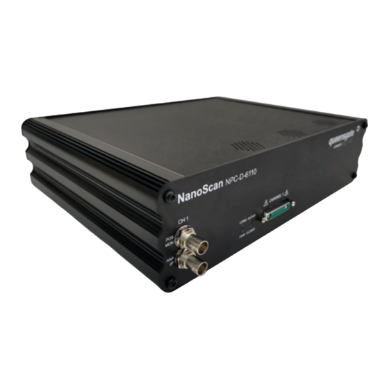
CONNECTING YOUR SYSTEM – FRONT OF UNIT
POS MON connector analogue
position monitor output BNC
connector(s)
Single ended output(s)
ANA I/P connector
Signal used to control the stage position
analogue command input
BNC connector(s)
Single ended output(s)
CONNECTING YOUR SYSTEM – REAR OF UNIT
Earth stud – M4 threaded provides additional
On/off
switch
ground connection to reduce interference of
background electrical noise
Do not raise above 0V ground potential
PWR connector
Provides power to controller electronics
4 pin mini-DIN with screen input
+24V DC ±0.75V @ 5A
Only connect an approve power supply
The NanoScan SP series sample scanners and the NanoScan OP400 objective
positioner have basic control within NIS-Elements using the NanoScan Z functionality.
COMS indicator LED
indicates status of communications with
connected computer
Not lit = No communications taking place
GREEN lit or flashing = Communications active
PWR indicator LED
Indicates power status and controller ready
RED steady = Controller configuring/not
ready (can take up to 30 seconds)
GREEN steady = Controller powered and
ready for operation
ETHERNET connector is used to communicate
with controlling computer dual connector for
SYNC IN/OUT connector
Provides RS-232 connection with connected
computer using supplied gender changer adapter
Also used to synchronize multiple 6000 controllers
9-pin D-type socket
www.prior.com
IN POS indicator LED
Indicates status of stage position in CLOSED loop mode
OFF = Stage has not reached desired position
ORANGE = Stage settings being loaded on connection
GREEN = Stage has reached desired position
Nanomechanism connector provides all
connections to nanomechanism
NOTE: High voltage present on connector
– up to 160V DC
Indicates status of control loop
OFF = Stage not connected
ORANGE = Stage settings being loaded on connection
RED = Controller operating in OPEN loop mode
GREEN = Controller operating in CLOSED loop mode
YELLOW = Controller servo output frozen
pass-through connection
Provides digital inputs and outputs for interfacing controller
to external equipment TRIG inputs and outputs
Stepped inputs and outputs
MUST use shielded cable
CLOSED indicator LED
USB type B connector is used
to communicate with
controlling computer
DIGITAL I/O connector
IN POS outputs
25-pin D-type socket,
5V TTLinputs/outputs
Advertisement
Table of Contents

Summary of Contents for Prior Queensgate NanoScan NPC-D-3110
- Page 1 TRIG inputs and outputs +24V DC ±0.75V @ 5A Also used to synchronize multiple 6000 controllers IN POS outputs Only connect an approve power supply 9-pin D-type socket Stepped inputs and outputs 25-pin D-type socket, 5V TTLinputs/outputs MUST use shielded cable www.prior.com...
- Page 2 Once installed navigate to Device Manager and select the USB to Serial Port COM setting. Make a note of the COM port used. Open NS-Elements and navigate to the manage device section; install devices as shown below and select Prior ProScan III/OptiScan III. www.prior.com...
- Page 3 DEVICE MANAGER Set the port to the setting found under device manager. Under manage devices within element select Prior ProScan III/OptiScan III and then select Z Piezo. www.prior.com...
- Page 4 Within the Z Piezo configuration set the travel range. This is 400um for the NanoScanOP-400 and NanoScanSP-400 and 600um for the NanoScanSP-600. The conditions for operation are set within the capture Z series page within NS-Elements. Here you can set the step size, direction and number of steps to build a Z stack. www.prior.com...
Need help?
Do you have a question about the Queensgate NanoScan NPC-D-3110 and is the answer not in the manual?
Questions and answers