
Summary of Contents for Amphenol Excel Mate CC
- Page 1 AMPHENOL PCD SHENZHEN EXCEL|MATE CC Electric car charging coupler www.amphenolpcd.com.cn...
-
Page 2: Table Of Contents
CONTENT PRODUCT INTRODUCTION .....……….....……..………...………..2 SPECIFICATIONS ...……………………………………………....….…...... 3 ChARgINg mODES ClASSIFICATION ……………..……….…..………...………..4 INSERT ARRANgEmENT ...………....…..…..………...………..……….……... 5 CIRCUIT DIAgRAm: VEhIClE SIDE ..……………………..………...………..…..6 CIRCUIT DIAgRAm: ChARgINg STAKE SIDE ............7 AC COUPlER DImENSIONS ……………………..………..........8 PANEl mOUNTINg DImENSIONS ...………….…………....……......9 INSERT ARRANgEmENT (DC) ................ -
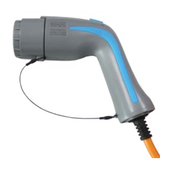
Page 3: Product Introduction
PRODUCT INTRODUCTION Amphenol PCD Shenzhen charging couplers are all compliant with GB/T 20234.1/2/3-2015 standards. User-friendly, easy to unmate, IP 55 (mated). High current contacts with Amphenol Radsok Technology. -
Page 4: Specifications
MECHANICAL Mating cycles ≥ 10000 cycles Connector (in mated condition) retention force: Unmating 100N Max AC coupler Mating 200N Min DC coupler Unmating 140N Max Mating 200N Min ELECTRICAL AC (R6) DC (R12) Rated current 63A Max 250A Max Rated voltage 250V/440V AC 750V/1000V DC Contact resistance... -
Page 5: Charging Modes Classification
ChARgINg mODES ClASSIFICATION ChARgINg mODE 2: When connecting electric vehicle to AC network, the plug and socket-outlet at power supply side shall comply with requirements of gB 2099.1. Phase line, neutral line and protective earth conductor shall be used at power supply side and the residual current operated circuit breaker shall be used at power supply side. -
Page 6: Insert Arrangement
insErT ArrAngEMEnT AC Coupler insert arrangement National standard VEhIClE INlET VEhIClE CONNECTOR CONFIgURATION Contacts Number & function Rated Voltage & Current function 250V/440V 16/32A AC power 250V/440V 16/32A Neutral PE, connect charging stake and vehicle chassis ground 30V 2A Charging confirmation 30V 2A Control confirmation Back up contact... -
Page 7: Circuit Diagram: Vehicle Side
CIRCUIT DIAgRAm: VEhIClE SIDE VEhIClE CONNECTOR VEhIClE INlET Mains (L1) Mains (L1) Back up 1 (L2) Back up 1 (L2) Back up 2 (L3) Back up 2 (L3) Neutral (N) Neutral (N) Ground (PE) Ground (PE) Charging confirmation (CC) Charging confirmation (CC) Control confirmation (CP) Control confirmation (CP) -
Page 8: Circuit Diagram: Charging Stake Side
CIRCUIT DIAgRAm: ChARgINg STAKE SIDE PlUg SOCKET-OUTlET Mains (L1) Mains (L1) Back up 1 (L2) Back up 1 (L2) Back up 2 (L3) Back up 2 (L3) Neutral (N) Neutral (N) Ground (PE) Ground (PE) Charging confirmation (CC) Charging confirmation (CC) Control confirmation (CP) Control confirmation (CP) -
Page 9: Ac Coupler Dimensions
AC COUPlER DImENSIONS PlUg VEHICLE CONNECTOR CHARGING STAKE PLUG SOCKET E-lock E-lock VEhIClE INlET SOCKET-OUTlET... -
Page 10: Panel Mounting Dimensions
mOUNTINg INSTRUCTIONS VEhIClE INlET mOUNTINg INSTRUCTION Wall Sealing gasket (selective) Frange square Panel installation guide SOCKET-OUTlET mOUNTINg INSTRUCTION Wall Sealing gasket (selective) Frange square E-lock Panel installation guide... -
Page 11: Insert Arrangement (Dc)
INSERT ARRANgEmENT DC Coupler inserts arrangement National standard VEhIClE INlET VEhIClE CONNECTOR CONFIgURATION Contacts Number & Rated Voltage & Current function function 750V/1000V 125/250A DC+, connect DC+ and battery+ DC - 750V/1000V 125/250A DC -, connect DC- and battery - PE, connect power supply equipment and vehicle chassis ground Charging communicattion CAN_H, connect... -
Page 12: Dc Circuit Diagram
DC CIRCUIT DIAgRAm Charging stake Plug Socket Electric vehicle (DC+) (DC+) (DC-) (DC-) Chassis ground (PE) Chassis ground (PE) Charging communication CAn_H (s+) Charging communication CAn_H (s+) Charging communication CAn_H (s-) Charging communication CAn_H (s-) Charging confirmation (CC1) Charging confirmation (CC1) Charging confirmation (CC2) Charging confirmation (CC2) Low voltage auxiliary power + (A+) -
Page 13: 80A Dc Coupler Dimensions
80A DC COUPlER DImENSIONS VEhIClE CONNECTOR DC CIRCUIT DIAgRAm (DC+) (DC-) Chassis ground (PE) Charging communication CAn_H (s+) Charging communication CAn_H (s-) Charging confirmation (CC1) Charging confirmation (CC2) Low voltage auxiliary power + (A+) Low voltage auxiliary power - (A-) E-LOCK (-) E-LOCK (+) E-LOCK (signal) -
Page 14: 125A To 250A Dc Coupler Dimensions
125A TO 250A DC COUPlER DImENSIONS VEhIClE CONNECTOR VEhIClE INlET mOUNTINg INSTRUCTION... -
Page 15: Product Series Summary
PRODUCT SERIES SUmmARY ChARgINg mODE 2 ChARgINg mODE 3 ChARgINg CIRCUIT INTERRUPTINg DEVICE (CCID) VEhIClE CONNECTOR + PlUg ChARgINg mODE 4 (80A) ChARgINg mODE 2 & 3 VEhIClE CONNECTOR VEhIClE INlET ChARgINg mODE 4 (125A TO 250A) VEhIClE CONNECTOR VEhIClE INlET... -
Page 16: How To Order
hOW TO ORDER HVCO R6 PSXXX LXXXX XXXX Connector type: M: Plug F: Receptacle E: Electric switch Used for: - AC vehicle connector - and DC plug Omit: No electric switch needed L: Electronic lock (Only for DC plug) B: New national standard (2015) T: Thermistor (for rated current over 16A) Omit: No thermistor needed S: Charging stake side... -
Page 17: Part Numbers
1. Cable section & pin installations are compliant with the national standards. Please contact us if any alternative installation is desired. 2. Cable assembly is recommended to be done by Amphenol PCD Shenzhen, for professional and safety reasons. for any special request, please contact us. -
Page 18: Vehicle Inlet - 90° Right-Angle
VEhIClE INlET - 90° RIghT-ANglE P/N: HVCO02R12Sf935RDL0000, 125A, 1000V DC Max HVCO02R12Sf970RDL0000, 200A, 1000V DC Max FRONT mOUNTED INSTAllATION INSTRUCTIONS: VEhIClE INlET... -
Page 19: Dc Vehicle Inlet (Small Size) - Front Mounted
DC VEhIClE INlET (SmAll SIZE) - FRONT mOUNTED P/N: HVCO01R12Sf935RL0000, 125A, 1000V DC Max HVCO01R12Sf970RL0000, 250A, 1000V DC Max REAR mOUNTED INTAllATION INSTRUCTIONS: DC VEhIClE INlET (SmAll SIZE) P/N: HVCO02R12Sf935RL0000, 125A, 1000V DC Max HVCO02R12Sf970RL0000, 250A, 1000V DC Max... - Page 20 Email: inquiry@amphenolpcd.com.cn www.amphenolpcd.com.cn Notes: Amphenol PCD Shenzhen has made every effort to ensure that the information contained in this catalog is accurate at the time of publication. Specifications or information stated in this publication are subject to change without notice.
Need help?
Do you have a question about the Excel Mate CC and is the answer not in the manual?
Questions and answers