Table of Contents
Advertisement
Advertisement
Table of Contents

Subscribe to Our Youtube Channel
Summary of Contents for Tec-Innovation InnoMake v.1
- Page 1 User manual Version: 03 / 2021...
-
Page 2: Table Of Contents
Table of Contents 1. Introduction .................. 4 1.1. Trade name and identification ............4 1.2. Explanation of symbols ..............5 2. Product description ..............6 2.1. Getting to know the product components......... 7 2.2. Control elements and interfaces ............ 10 2.3. - Page 3 5.2. Information and measures in case of environmental influences ..29 6. Handling ..................31 6.1. Storage and transportation ............31 6.2. Cleaning and disposal ..............32 7. Technical data ................33 8. Legal information ............... 35 9. Closing remarks ................. 36 TDIM1_4_User Manual_1...
-
Page 4: Introduction
Introduction We at Tec-Innovation GmbH are happy that you have chosen our InnoMake product. InnoMake is an intelligent obstacle detection system with which we want to provide greater walking safety and reduce barriers in the interaction with our environment. For the unrestricted and safe use of InnoMake, it is important that you carefully read through this entire user manual and also follow the safety instructions. -
Page 5: Explanation Of Symbols
1.2. Explanation of symbols An understanding of the following symbols in the table below are important and helpful for this user manual and the labelling on the product. Symbol Description The symbol of an open book with the letter “i” for “Information”... -
Page 6: Product Description
You can have the App user manual and this user manual read aloud with the aid of a reading programme on our website www.tec-innovation.com. If required, we will also send you the App user manual in paper form to your door free of charge. -
Page 7: Getting To Know The Product Components
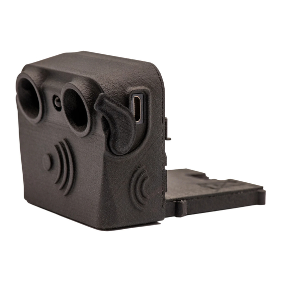
The above-mentioned product components are shown in connection with each other in the drawing below. The drawing shows a shoe with a narrow midsole, the concealed compartment at the front of the shoe and the underlying profiled sole. An attachment part with the processing unit is shown in front of the shoe. The attachment part contains the two ultrasonic sensors facing forward and away from the shoe for obstacle detection in the walking direction. - Page 8 Shoes with built-in metal tracks If you hold one of the two shoes in your hand, you can feel the compartment for the attachment parts in front, at the front of the shoe. This compartment is integrated in the shoe midsole and results from an integrated metal track and gap above.
- Page 9 Sensors are installed in the two notches on the front side. These two sensors send and receive ultrasonic waves while your InnoMake is switched on. When your InnoMake is in use, the ultrasonic sensors point in your walking direction and detect obstacles in front of you. An LED is integrated in the middle between the ultrasonic sensors.
-
Page 10: Control Elements And Interfaces
An LED is installed on the left next to the push button, which provides you with colour feedback on the battery status when the battery is charging. Of course, InnoMake also provides you with acoustic information on the battery charge level. Refer to section 4.3. Information on application will follow in section 4. -
Page 11: Product Variants And Shoe Models
A list of our available shoe models and possible colour versions can be found on our website at www.tec-innovation.com/schuhmodelle/. Would you like to have more than one pair of shoes on your shoe rack for... -
Page 12: Accessory: Innomake App
You can always have a second (or third, etc.) pair of shoes adapted for the use of InnoMake. To this end, we work alongside our partner Waldviertler Werkstätten GmbH and together with selected orthopaedic shoemakers who can fulfil this wish for you. You can then easily insert the attachment parts from the right and left shoe into another pair and use the same settings adapted for you. -
Page 13: Purpose And Function
App and its functions. You can have the App user manual read aloud with the aid of a reading programme on our website www.tec-innovation.com. The QuickGuide starts automatically when you open the InnoMake App for the first time. -
Page 14: Intended Users
distance from an object in the walking direction is communicated directly to you by a vibration in the shoe. The vibrational feedback varies in frequency in proportion to the measured object distance, i.e. ▪ the closer the object, the faster the vibrational feedback ▪... -
Page 15: Area Of Application And Environmental Conditions
InnoMake is intended for use by people with impaired vision, especially people with severe visual impairment and blind people who are able to stand and walk independently. Since, on the one hand, you operate the InnoMake product as a user and, on the other hand, you experience the medical benefit of the product, you are a patient and operator at the same time in medical technology language. -
Page 16: Application
There are also application restrictions in case of extreme natural influences, such as e.g. flooding, fire, hail or temperatures above 40°C and below -5°C, as well as hazardous environments, such as e.g. in constructions sites or workshops. The detailed permissible environmental conditions can be found in the technical data in section 7. -
Page 17: Charging The Battery
Information on changing the measurement range can be found in section 4.6. Switching off In order to switch an attachment part off, hold the push button on the back of the attachment part for at least 2 seconds. A descending audio signal indicates when the attachment part is switched off. -
Page 18: Checking The Battery Charge Level
inserting into the micro-USB socket. Then connect the power supply unit of the battery charger to a voltage source (220-230V) O T E Only use the battery charger included in the product scope to charge the battery in your InnoMake because the power supply unit meets the safety standard required for medical devices. -
Page 19: Prepare Shoes And Attachment Parts
High tones indicate the charged battery capacity, low tones indicate discharged battery capacity. The following table describes the five possible tone signals: Tone signal Battery charge level 4x low 0% to 7 % charged 1 x high / 3 x low 8% to 25% charged 2 x high / 2 x low 26% to 50% charged... -
Page 20: Your First Steps
When using the InnoMake App, please follow the instructions in the App user manual because the attachment parts are assigned to “left” and “right” in the App. 4.5. Your first steps If you are using your InnoMake for the first time, familiarise yourself with the InnoMake functions in a known environment first. - Page 21 Since we are all on the move in different and changing environments, you have the possibility of changing the measurement range of your InnoMake for each attachment part separately and adjusting for your use. The distance to objects can be provided as feedback between 0.3 and 1.5 metres or between 0.3 and 4.0 metres.
-
Page 22: Activate Intelligent Mode
4.7. Activate intelligent mode The InnoMake attachment parts are equipped with an intelligent mode that you can activate at any time. When intelligent mode is activated, an attachment part detects when the respective shoe is in a resting position. Should the shoe with the attachment part be in a resting position for 3 seconds, the attachment part will switch to sleep mode and stop providing instant feedback. -
Page 23: After Use
You can activate the LED by pressing the push button on the back of the attachment part. In order to avoid damaging the casing, do not use too much force when pressing the push button. In order to activate or deactivate the LED, press the push button 3 times in quick succession. -
Page 24: Attachment Part Warning Tones
See: Measures in case of environmental influences in section 5.2 • Are the attachment part batteries charged? See: Charging the battery in section 4.2 4.10. Attachment part warning tones Your attachment parts emit certain warning tones in two situations. 1st warning tone: If you do not charge the battery in an attachment part for a long period of time, it can occur that the battery runs empty while in use. -
Page 25: Overview Of Innomake Signals
In this case, we recommend taking the shoes off and allowing the product to cool down before touching the attachment parts. Other safety instructions and measures can be found in section 5. 4.11. Overview of InnoMake signals The signals listed in the following table are only emitted in the switched-on and active InnoMake state. -
Page 26: Safety Instructions
Button Event Audio signal LED signal press section Charge level: 4x high 76% – 100% 1x long / low, Activate LED 1x short / high 3x short Deactivate LED 1x long, 1x short 2x long / low, Activate intelligent mode 1x short / high 4x short Deactivate... -
Page 27: Information And Measures In Case Of Product (Mal)Functions
▪ The compartments in the shoes adapted for InnoMake are exclusively intended for the insertion of InnoMake attachment parts. ▪ In order to prevent the contamination of the compartments, do not use your InnoMake shoes without the correctly inserted attachment parts. ▪... - Page 28 Malfunctions Possible causes Necessary action Clean your InnoMake, Dirt on the sensors see section 6.2 Approach or move away from Obstacle is not in the an obstacle in the walking measurement range between direction to bring it into the 0.3 and 4.0 metres measurement range and get feedback Material or shape of an object...
-
Page 29: Information And Measures In Case Of Environmental Influences
Malfunctions Possible causes Necessary action Nearby sources of interference in the same frequency range of the Switch off and on again and ultrasonic sensors, e.g. a wait for operational state jingling keychain, other ultrasonic sensors The measurement range was An obstacle is Stand still while adjusting the adjusted immediately before detected too late... - Page 30 This section provides you with information in connection with external influences or environmental conditions that you may encounter when using your InnoMake. Temperature ▪ Since the attachment part electronics are equipped with overheating protection, it may happen that an attachment part switches itself off due to high environmental temperatures (see section 4.10).
-
Page 31: Handling
If devices in your home environment cause malfunctions and functional failures, please switch your InnoMake off and on again. Resetting the system should restore the full functionality of your InnoMake in these cases. The switching on and off of InnoMake is described in section 4.1. Listed below are examples of potential influences in the home environment which, among other things, can cause your InnoMake to not measure distances to obstacles. -
Page 32: Cleaning And Disposal
The detailed permissible environmental conditions can be found in the technical data in section 7. Keep your InnoMake and the USB charging cable out of the reach of small children < 3 years. There is a risk of strangulation due to the length of the USB cable of 1 metre. -
Page 33: Technical Data
Technical data This section contains a table concerning InnoMake’s technical data, the environmental conditions, the built-in battery and the InnoMake App. Product Model InnoMake v.1 Year of manufacture 2021 Medical device Class 1 Hardware version number IMK1v4 (as of 20.07.2020) Firmware version number IMK-1.0.0 (as of 20.07.2020) - Page 34 Interfaces Micro-USB, Bluetooth® Range of the InnoMake Bluetooth Max. 15 metres depending on terminal connection to the InnoMake App Bluetooth: Frequency band 2.402 - 2.480 GHz Bluetooth: Transmission power RF TX Power: 0 dBm Protection rating IP 57 Environmental conditions -5°C to +40°C, 15% to 93% relative Operation humidity, non-condensing...
-
Page 35: Legal Information
Directive 2011/65/EU (Restriction of Hazardous Substances Directive) InnoMake is a class 1 medical device. We at Tec-Innovation GmbH have therefore drawn up the declaration of conformity under our sole responsibility pursuant to Annex VII of the Medical Device Directive. Reporting of incidents... -
Page 36: Closing Remarks
▪ medical or surgical intervention to prevent the three consequences above. 9. Closing remarks We hope you enjoy your reliable InnoMake and enjoy greater safety and comfort on your journeys. TDIM1_4_User Manual_1...
Need help?
Do you have a question about the InnoMake v.1 and is the answer not in the manual?
Questions and answers