
Related Manuals for Janus AC-4CM10-640-F-20-000

Summary of Contents for Janus AC-4CM10-640-F-20-000
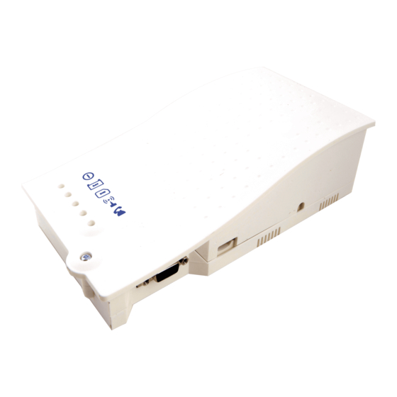
- Page 1 Installation & Operations Manual 4G Cellular Gateway Part #: AC-4CM10-640-F-20-000 415 Oser Avenue, Suite Q Hauppauge, NY 11788 RP8500DCPJ Ver. 2 800-527-9156 www.avire-global.com/us 11/20...
- Page 2 800-527-9156 www.avire-global.com/us Table of Contents Items Needed ....... Page 3 Setting up the Cellular Gateway .
- Page 3 • Standard size AT&T GSM SIM card (25mm x 15mm) with voice and data IMPORTANT NOTE: If the connected elevator phone is not equipped with external power, you must order Janus part # POWPK-12VC. Setting up the Cellular Gateway 1. Open the Cellular Gateway by unscrewing the screw on the left side of the front cover with a Phillips screwdriver and gently pull up on the left side.
- Page 4 5. Connect the phone(s). The Cellular Gateway provides an RJ11 jack or hardwired screw terminals for connecting devices. Do not exceed 1,000 feet. RJ11 Jack: a. Take a male RJ11 phone line cord or plug it into the J1A jack on the Cellular Gateway. b.
- Page 5 J8 - CANBUS: CANBUS can only be used with specific Avire products. See supplemental manual. J2 - External Antenna: Connect the provided external antenna to the J2 connector. Only antennas approved by Janus should be used otherwise the Cellular Gateway may not function properly and may be damaged. J3 - BATTERY...
- Page 6 LED Indicators This Cellular Gateway has five indicator LEDs that constantly report the device status. The indicators will be red, amber, or green. Each indicator will be fully on, fully off, or flashing. The table below provides an overview of what each colored LED indicates: RUN LED FLASHING...
- Page 7 Single Pair EMS5 System Wiring Diagram: Antenna Do not exceed 120vac 1,000’ Power Cellular Single PORTS Single Pair Gateway Pair TELCO Janus Elevator EMS5 Phone CALL DIRECTOR LOCAL ® SERVICE Building Communication System Janus COM-ERROR Elevator ACTIVE CALL CHARGING Phone...
- Page 8 The battery provides 4 hours of talk time. The battery should be replaced every 4 years. Only install batteries authorized by Janus, and only allow qualified personnel to replace the battery. The battery should be properly recycled and not disposed of with unsorted household waste. Please take all necessary precautions when changing the battery.
Need help?
Do you have a question about the AC-4CM10-640-F-20-000 and is the answer not in the manual?
Questions and answers