Advertisement
Quick Links
English
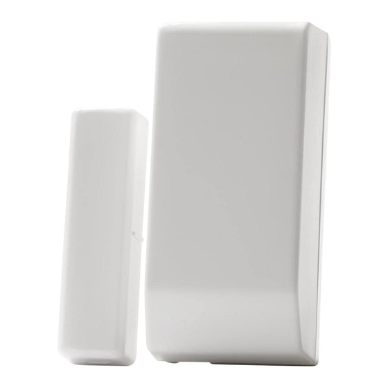
The EL-2601 is a magnetic door and window contact designed for
use with Electronics Line 3000's supervised wireless range of
receivers.
Installation Instructions
1.
To open the housing, insert a small screwdriver at the bottom
of the unit between the front and back cover and twist the
screwdriver to release the cover.
2. Remove the divider separating the battery from the contacts
on the battery holder. When you apply power and the Tamper
switch is open, the EL-2601 enters Test mode during which a
transmission is sent every few seconds. You can terminate
Test mode by closing the Tamper switch. Test mode is
automatically terminated after approximately five minutes.
Note: Due to the occurrence of voltage delay in lithium
batteries that have been in storage, the batteries may initially
appear to be dead. In this case, leave the unit in Test mode for
a few minutes until the battery voltage level is stabilized.
3.
While the EL-2601 is in Test mode, set the receiver to
Registration mode and make sure that the EL-2601's LED
lights up at least twice. After registration, close the Tamper
switch to terminate Test mode. The receiver allocates a
transmitter number to each registered unit. Write this number
and the number of the zone on the sticker provided. Affix the
sticker inside the front cover for future reference.
Alternatively, the EL-2601 can be registered to the receiver by
manually entering the transmitter's serial number.
4.
Before permanently mounting the unit, test the transmitter
from the exact mounting position. If necessary, improve the
position of the transmitter.
5.
To remove the PCB, press the PCB release tab and carefully
lift the board and slide the board away from the back cover.
Note: When handling the PCB, do not apply pressure on the
antenna.
6. The EL-2601 is able to operate in three modes: Magnetic Switch,
Universal Transmitter or a combination of the two (see Table 1). If
connecting a wired contact loop (N.C.), connect the terminal block
as follows: 1 - Alarm; 2 - GND. For this purpose, a wiring knockout
is provided in the back cover.
7. Mount the back cover using two screws and replace the PCB. Use
ISO 7050 (ST3.5 x 22) or similar countersunk screws so that the
screw head will not touch the PCB – see Figure 2.
8. To open the magnet's housing, insert a small screwdriver into one
of the pry-off slots located at either end of the magnet's back cover
and lift to separate from the front cover.
9.
Mount the back cover of the magnet using two screws. Make
sure that the guideline on the magnet is correctly aligned with
the guideline on the transmitter.
magnet further than 1cm from the transmitter.
10. Test the transmitter, making certain that the LED is lit when
opening the door/window and again when closing.
11. Close the front covers of the transmitter and the magnet.
Technical Specifications
Antenna: Built-in Internal Whip
Frequency: 868.35, 43 3.92 or 418MHz FM
Power: 3.6V ½ AA Lithium Battery
Caution: Fire, explosion and severe burn hazard!
Do not recharge, disassemble or heat above 100°C.
Current Consumption: 25mA (transmission)
Loop Input Voltage Range: 0-15VDC/AC (peak to peak)
RFI Immunity: 40V/m
Operating Temperature: 0-60°C
Note: Do not install the
10µA (standby)
1cm max.
Figure 1: EL-2601 (cover off)/Figure 1: EL-2601
(sans couvercle) /Figura 1: EL-2601 (sin tapa)
1.
Magnet/Aimant/Magnético
2.
Antenna/Antenne/Antena
3.
Battery Holder/Support de batterie/
Soporte de la Batería
Note:
4.
LED Indicator/Indicateur de LED/
Indicador LED
5.
Operation Mode Jumper/Cavalier de mode
opérationnel/Jumper de Modo de Operación
6.
Tamper Switch/Contact
d'autoprotection/Llave del Tamper
7.
Location of Wiring Knockout/Prédécoupe
de passage des câbles/Localización del
agujero de salida de cables
8.
Loop Terminal Block/Borniers/Lazo Bloque
de Terminales
9.
PCB Release Tab/Touche de relâchement
PCB/Traba del PCB
Jumper Position/
Position Cavalier/
Posición Jumper
Pins 1 & 2/
Broche 1 & 2/
Pines 1& 2
Pins 2 & 3/
Broche 2 & 3/
Pines 2 & 3
Jumper Removed/
Cavalier Enlevé/
Jumper Removido
Table 1: Operation Mode Jumper/Tableau 1: Cavalier de Mode
Opérationnel/Tabla1: Jumper de Modo de Operacion
PCB
HOUSING/
BOÎTIER/
CAJA
EL-2601
Operation Mode/
Operation Mode
Operation Mode
Universal Transmitter/
Transmetteur universel/
Transmisor Universal
Magnetic Switch/
Contact Magnétique/
Contacto Magnético
Magnetic + Universal/
Magnétique+ Universel/
Magnético + Universal
Figure 2: Mounting Screw Position/
Figure 2: Position de la vis de montage/
Figura 2: Posición Tornillo de Montaje
Advertisement

Summary of Contents for Electronics Line EL-2601
- Page 1 6. The EL-2601 is able to operate in three modes: Magnetic Switch, Loop Terminal Block/Borniers/Lazo Bloque Universal Transmitter or a combination of the two (see Table 1). If de Terminales connecting a wired contact loop (N.C.), connect the terminal block...
- Page 2 France: ZI-61, rue du Marché Rollay, 94500 Champigny-Sur-Marne. Tel: (33-1) 45.16.19.20, Fax: (33-1) 45.16.19.29 All data is subject to change without prior notice. In no event shall Electronics Line 3000 Ltd. (EL3K) be liable for an amount in excess of EL3K.’s original selling price of this product, for any loss or damage whether direct, indirect, incidental, consequential or otherwise arising out of any failure of the product.