Advertisement
Quick Links
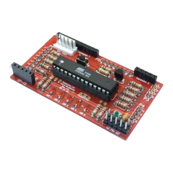
The Solarbotics SUMOVORE
Atmel ATMega8L Brainboard Add-on
Version 2.0
Ready to step up from the discrete brain on
your stock Sumovore?
Here's the Atmel ATMega8L-based Brainboard to take over!
The ATMega8L is a very popular microcontroller, supported by many
programming languages (some free!). Program it with a home-made parallel-
port cable, or use the popular Atmel STK-500 development system.
The new version 2 brainboard adds full I2C interface support, better
programmability and the ability to add bread-board space!
It's a fast, inexpensive, and very powerful upgrade for your
Solarbotics Sumovore Robot Kit!
(Sumovore Sumo robot kit and programmer/DB25 printer cable req'd)
Produced by
®
Ltd
Document Release: November 20, 2006
Advertisement

Summary of Contents for Solarbotics SUMOVORE
- Page 1 The new version 2 brainboard adds full I2C interface support, better programmability and the ability to add bread-board space! It’s a fast, inexpensive, and very powerful upgrade for your Solarbotics Sumovore Robot Kit! (Sumovore Sumo robot kit and programmer/DB25 printer cable req’d) Produced by ® Document Release: November 20, 2006...
-
Page 2: Disclaimer Of Liability
Solarbotics Ltd. reserves the right to make substitutions and changes to this product without prior notice. - Page 3 1 - ATMega8L 28 pin Carrier 1 - Atmel ATMega8L Microcontroller 1 - Reset Button 1 - QRD1114 edge sensor (for Sumovore’s middle sensor) 1 - 5-Socket programming header 1 - Polarized 5-Pin I2C interface header 1 - 10-Pin (2 rows of 5 pins) STK-500 programming header...
- Page 4 The ATMega8L Brainboard Introduction Looking for a more flexibility out of your Sumovore? Well, welcome to the next in our series of brainboards - the ATMega8L. The ATMega8L offers an impressive list of features, including (but not limited to): 8kB flash memory...
- Page 5 The ATMega8L Brainboard Building It - Steps 1, 2, 3 Remember - when you’re building this kit, you must bend the resistors down right near the resistor body. This PCB is designed on the tight side, so being compact counts! Step 1 - 3 x 240 Ohm Resistors (Red / Yellow / Brown): These resistors are part of the SP12 programming interface that buffer the signals.
- Page 6 The ATMega8L Brainboard Steps 4, 5, 6 Step 4 - 100k (Brown / Black / Yellow) Resistor: Install the 100k resistor in position R10. This resistor works with the transistor to turn on the programming LED. Step 5 - 2 x 47k (Yellow / Violet / Orange) Resistors: The 47k resistors are installed in positions R11 and R12.
- Page 7 The ATMega8L Brainboard Steps 6, 7 Step 7 - Tiny Red Indicator LEDs: You can’t have a robot without blinky lights. Really. Besides, they truly are useful for figuring out what your robot is thinking at any moment. Unlike resistors, these have to be installed the right-way-around. Look underneath the LED to see which side has the painted bar.
- Page 8 The ATMega8L Brainboard Steps 9, 10, 11, 12 Step 9 - Reset Button: Sometimes you have to reach out and ... make that robot behave! We do this by installing the reset pushbutton at position Reset. The holes may be a little snug, so if you want it to sit flat to the PCB, use some force to get it in there.
- Page 9 The ATMega8L Brainboard Steps 13, 14, 15 Step 13 - I C Header: Going to interface to other I C peripherals? You’ll need to install this header. Make sure the big flat tab is nearest the top of the PCB, where the long line is shown on the symbol.
- Page 10 The ATMega8L Brainboard Steps 16, 17 Step 16 - 8 Pin Headers (x 2): To attach your new Brainboard to the robot, you’ll need to solder the two 8-pin headers in positions P1 and P2, but on the underside. I don’t think you heard me, so... NOTE / IMPORTANT / READ ME, DARN IT: Install all these pins on the bottom of the PCB.
- Page 11 The ATMega8L Brainboard Step 18, 19 Step 18 - Short Expansion Port Headers: Although you may not use an expansion board immediately, it’s best to install the headers now so they don’t get lost. Install them on the top-side in Expansion 1 and Expansion 2 spots. These headers are special in that they’re short, specially selected to mate with short-pins on the expansion breadboard.
- Page 12 The ATMega8L Brainboard Step 20 On the Sumovore, you have to add the center edge-sensor to make full use of the Atmel Brainboard: Step 18 - Installing the 5th line sensor: Yank the edge-sensor board out of your Sumovore, and install the included line sensor in position ‘Edge3’, just like you did when you originally built your Sumovore.
- Page 13 There are three sections to the code, startup, Sumo, and the Line-follower. If you start your Sumovore on a black sumo-ring surface, the low signal from the edge sensors kick into sumo mode. White surface reflection (white table with black...
- Page 14 “Pin1” lines with the red stripe on the cable, and make sure the motor enable switch is off. If you don’t, the STD-500 will try to power up the motors. Using “GCC” sourcefiles from Solarbotics.com, open “Sumovore_2.aps” into the AVRStudio programming suite. “Sumovore_2.c” and “Sumovore_2.hex” will automatically open.
- Page 15 The ATMega8L Brainboard Brainboard Schematics ATMega8L Microcontroller Pin Usage Brainboard I/O Reset I2C (SCL / PC5) IR Left (RxD /PD0) Edge Right / Pin5Exp2 (I2C SDA/PC4) IR Right (TxD / PD1) Edge Center Right / Pin4Exp2 (PC3) LED1 / Pin7Exp1 (PD2) Edge Center / Pin3Exp2 (PC2) LED2 / Pin8Exp1 (PD3) Edge Center Left / Pin2Exp2 (PC1)
- Page 16 If you have any questions regarding this kit, please contact us! Solarbotics Ltd. 201 - 35th Avenue N.E. Calgary, Alberta, Canada T2E 2K5 Toll Free: 866-276-2687 / 403-232-6268 Fax: (403) 226-3741 Website: http://www.solarbotics.com Email: Sales@solarbotics.com © Copyright Solarbotics Ltd., 2006...
Need help?
Do you have a question about the SUMOVORE and is the answer not in the manual?
Questions and answers