Table of Contents
Advertisement
WARRANTY CERTIFICATE
(
CLIENT'S COPY)
/
/
TECHNICAL DELIVERY DATE:
INVOICE NUMBER:
DEALERSHIP INFORMATION
NAME:
STAMP AND SIGNATURE:
CLIENT INFORMATION
NAME
:
PHONE:
ADDRESS
:
PURCHASED UNIT INFORMATION
MODEL:
MANUFACTURED DATE:
SERIAL NUMBER:
IMPORTANT!
Warranty issues will only be address if this certificate is properly
filled-out at the time of delivery by technician. This certificate must be
presented with every warranty claim, along with the sales invoice.
Advertisement
Table of Contents

Summary of Contents for Stara Hercules 10000
- Page 1 WARRANTY CERTIFICATE CLIENT’S COPY) TECHNICAL DELIVERY DATE: INVOICE NUMBER: DEALERSHIP INFORMATION NAME: STAMP AND SIGNATURE: CLIENT INFORMATION NAME PHONE: ADDRESS PURCHASED UNIT INFORMATION MODEL: MANUFACTURED DATE: SERIAL NUMBER: IMPORTANT! Warranty issues will only be address if this certificate is properly filled-out at the time of delivery by technician.
- Page 3 TECHNICAL DELIVERY TERMS (self-propelled) (this form must be completed by the technician and sent to Stara) DELIVERY DATE: INVOICE Nº: TECHNICIAN/DELIVERY AGENT: CUSTOMER DATA: NAME: PHONE: ADDRESS: PURCHASED PRODUCT DATA: MODEL: MANUFACTURED DATE: SERIAL Nº: INSTRUCTIONS AND DIRECTIVES TECHNICIAN FUNCTIONS:...
- Page 5 Conditions of the Warranty A) Stara guarantees its product “only to” the DEALERSHIP, and for the period of six months, starting on the day of delivery to the CLIENT, along with the original invoice and warranty certificate, which must be presented at the time of claim.
- Page 7 Constant Evolution HÉRCULES 10000/ STAINLESS SEEDER & FERTILIZER TRAILER INSTRUCTION MANUAL PARTS CATALOG STARA S.A. - Agricultural Machinery and Implements Industry AV. STARA, 519 Não-Me-Toque,RS - Brazil CEP 99470-000 Phone/Fax:+55 54 3332-2800 e-mail: stara@stara.com.br Home page: www.stara.com.br Nov./2010 - Revision 06...
-
Page 9: Table Of Contents
TABLE OF CONTENTS INTRODUCTION.........................06 MAIN COMPONENTS......................07/08 IDENTIFICATION PLATE......................08 3 - TECHNICAL SPECIFICATIONS..................09/10 4 - SAFETY INSTRUCTIONS....................10/11 MAINTENANCE.........................11/12 5.1 - Filter and oil change of the transmission system ............11/12 5.2 - Tire Pressure........................12 6 - MOUNTINGS AND ADJUSTMENTS..................13/25 6.1 - Montagem dos Cubos, dos Aros e Pneus no Eixo Rodado...????......13 6.2 - Wheel axle adjustments(options).. - Page 10 11.9 - Disc Assembly- 18-24; w/Vane 1 0-18/Complete ............50 11.10 - Disc Assembly 18-24/Right & Left; w/Vane 10-18/Complete ........51 11.11 - Disc Assembly- 18-24/Complete..................52 11.12 - Disc Assembly 18-24/Right & Left ................53 11.13 - Fertilizer Deflector Assembly ..................54 11.14 - Deflector Adjustment Support Assembly ..
- Page 11 Main Tank Cap/Grating Set ..................148 11.89 - Sample Collector Pckg(buckets) .................149 11.90 - Row Spreader(Optional) ..................150/151 11.91 - Upper Box Assy- Hercules 10000/S.S................152 11.92 - Row Spreader for Adjustable Tandem .................153 11.93 - Wheel Drive Axle with Pneumatic Brakes ..............154 11.94 - Hub/Pneumatic Brake Assy ..................155...
-
Page 13: Introduction
So, with that in mind, it is extremely important that the operational manual be read thoroughly, and should be consulted always when doubts or questions arise. Stara offers its after-market sales services, to assist you and your dealer, in the hopes of achieving the highest profitability and yield of your machine. -
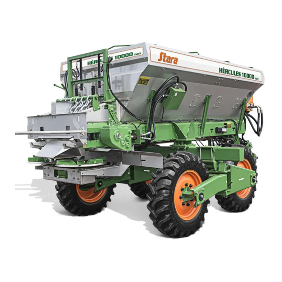
Page 14: Main Components
1 – COMPONENTS The 10000/Stainless Hercules is equipt with a basic set of components, as shown in figures 01 and 02 A - Chassis. Main Tank. O -Ladder. C - Fixed Gooseneck/ hitching arm (optional). P - Main Tank cap for fertilizer (optional). D - Adjustable Gooseneck/hitching arm(opt.) Q - Deflector for fertilizers. -
Page 15: Identification Plate
2 – IDENTIFICATION PLATE The ID plate (Figure 03) shows the model no. of the machine, weight, serial no., and also the date STARA S.A. IND. DE IMPLEMENTOS AGRÍCOLAS NÃO-ME-TOQUE - RS BRASIL manufactured . This information is fundamental in the MOD.:... -
Page 16: Technical Specifications
TECHNICAL SPECIFICATIONS/ HÉRCULES 10000 STAINLESS - w/f ixed gooseneck/hitching arm : 6,500 mm Length - w/adjustable gooseneck/hitching arm: 6,770 mm Height - W/tarp support arches: 2,500mm - 1,910mm Width (w/o tires): - Total weight (w/o tires): - 1,800kg - W/standard wheels: 10,000kg or 5,000/l - Load capacity and Volume - W/wheels using options: 5,000kg or 2,500/l - 13kg/ha to 6,000kg/ha... -
Page 17: Safety Instructions
TECHNICAL SPECIFICATIONS/ HÉRCULES 10000 STAINLESS (Dimensions) Hércules 10000 Stainless with: - Adjustable Gooseneck - Tire: TM64/R - 18.4/15-30 - 12PR 2600 6770 Figure 04 4 - SAFETY PRECAUTIONS The Hércules 10000/Stainless Spreader, is like any other piece of equipment, as with any agricultural implement or machinery, certain precautionary measures are indispensable for the avoidance of accidents. -
Page 18: Maintenance
-do not step on the conveyor while its moving; - retighten all screws/bolts before using the implement, take special care with the wheel nuts, the goose-neck engagement and transmission case supports; - after first 5 working hours, review all nuts and bolts and retighten as needed; - adopt as a standard procedure to inspect daily all the wheel nuts and bolts and the gooseneck 5 - MAINTENANCE So that all available resources of the implement can be fully appreciated, with durability and... -
Page 19: Tire Pressure
The oil quantity of each case is as follows: Triple case - 3/ l; Conveyor belt case - 7/ l; axle case- 0.6/l. - The first time oil change should be done after 50 work hours. - The gear case has a vent with a dip-stick to monitor the oil levels, which should be refilled when necessary. -
Page 20: Mountings And Adjustments
6 -MOUNTING AND ADJUSTMENTS The Hércules 10000/Stainless leaves the factory assembled, with the exception of the wheel/tire assemblies, the goose-neck and the optional items needed to work with granular or powdered products. It is important to note in this manual that certain components need special adjustments, be it in the application of powdered or granular products. -
Page 21: Wheel Axle Adjustments/Height
2,100 to 1,800 to 2,700mm 2,400mm Figure 07 Figure 08 2nd Option: allows for a wheel base adjustment width between 1,800 to 2,400mm (figure 08). 6.2.2 - Wheel axle height adjustment: To adjust for the height use the height extender, always observing the maximum weight limit of 5,000 kg. -
Page 22: Goose-Neck Mounting
6.3 - Goose-neck mounting The Hércules 10000/Stainless offers two goose-neck options, allowing for the needs of job diversities. The Fixed Goose-neck, shown on figure 10, is used in the distribution of limestone, in irregular terrain. In the application of products the Adjustable Goose-neck is used, allowing for the implement to follow the tractor in its course around curves, thus avoiding product built-up. -
Page 23: Braking System Adjustments
HÉRCULES WITH ADJUSTABLE GOOSE-NECK GEAR DRIVE SYSTEM POWER TAKE-OFF Figure 12 6.4 - Braking system adjustments The Adjustable Goose-neck Braking System on inclined terrain serves as a means to avoiding side swipes, providing a greater stability during the job. It leaves the factory fully adjusted,but it is field adjustable, depending on the need and application. -
Page 24: Configuration For Powdered Products (Limestone)
6.6.1 - Configuration when using powdered products (limestone): Consisting of the following items, which should be removed when working with granular products: Chain Set; Discs for Limestones and 2 Load Reducers (Figure 13). 2 LOAD REDUCERS CHAIN DISCS FOR LIMESTONE DISTRIBUTION Figure 13 6.6.1.1 - Mounting and adjusting discs for limestone:... -
Page 25: Configuration For Granular Products (Fertilizer)
On Figures 15, 16 and 17 we can better see the correct and incorrect ways to assemble the distribution discs and the vanes. IMPORTANT! Maintain the gear box axles greased, so as to facilitate the mounting and dismounting of the discs. CORRECT! LEFT RIGHT... -
Page 26: Mounting And Adjusting The Discs For Granular Applications
CAP UNIT FERTILIZER DISTRIBUTION DISCS FERTILIZER DEFLECTOR UNIT INCLINE SEPARATOR UNIT Figure 18 6.6.2.1 - Mounting and adjusting discs for granular seed The discs should be mounted to the gear box with butterfly screw, being careful to engage the disc channels with cotter pins onto the gear boxes, which are 90º... - Page 27 RIGHT CORRECT! LEFT Figure 20 - This is the proper mounting of the discs, which guarantee the adjustments and uniform distribution. IMPORTANT! Check the disc markings for : “E” or “L” for the left and, “D” or “R” for the right. Figure 20 WRONG INCORRECT!
-
Page 28: Adjusting The Deflector
6.7 - Deflector adjustments The deflector is used exclusively with granular products. It has the two selectable positions (position 1 and 2) - see figure 24, which should be verified before starting the job. The adjustment is directly affected by the type of application conditions: Position 1: for rate up to 150 kg/ha;... -
Page 29: Adjusting The Conveyor Gear Box
- Conveyor gear box adjustment The operation of the conveyor is done through the gear box, as shown on figure 26, there are three adjustable positions. The positions are used as follows: Position 1: is used for low flow rates (fertilizers under 1,500 kg/ha). -
Page 30: Adjusting The Drive-Wheel And The Conveyor Gear Box
6.9 - Adjusting the conveyor drive wheel and gear box The conveyor drive-wheel should be proportionally adjusted to guaranty its proper function, without jeopardizing its operation, and/or damaging components like the drive-shaft/cardan and the transmission gear boxes. Basically, follow the procedure listed below: - Always maintaing the conveyor drive-wheel tire (tire, 18 x 8.5-8 ATV MAX), centered with the machine’s tire, as shown on figure 28. - Page 31 2) Start the tractor, initializing the system (pressurize) again, according to figure 30. Figure 30 3) Distance the drive-wheel tire away from the conveyor at about 100mm in relation to the implements wheel as shown on figure 31. Following, with the tractor turned on, replace the bolt removed at step “1”, onto the nearest bolting pattern, re-tightening the nuts on the bolts.
-
Page 32: Using And Adjusting The Cardan/Drive-Shaft
6.10 - Using and adjusting the Cardan/ drive-shaft Due to various brands and models, it is necessary to adjust the length of the cardan in its first usage. 6.11 - Positioning and adjusting the triple box The operation of the triple box, which controls the distribution discs, has a specific setting which needs to be maintained, so that the product distribution will not be jeopardized, this is in regards to the positioning of the same, above the discs. -
Page 33: Problems, Possible Causes And/Or Solutions Of The Hyd.system
7 - HYDRAULIC SYSTEM PROBLEMS WHICH MAY OCCUR - POSSIBLE SOLUTIONS: SOLUTIONS CAUSES PROBLEMS Loose connections. Retighten with caution Leakage on screw-on Apply sealing tape Insufficient sealing connections/fixed hoses. and retighten with caution tape on threads. Retighten with caution Loose connections. Apply sealing tape Insufficient sealing Leakage on... -
Page 34: Instructions And Usage Of The Calculation Scale
8 - INSTRUCTIONS ON THE USAGE OF THE CALCULATION SCALE: For adjustments to be calculated using the scale, firstly it is necessary to, calculate the product density to be dispensed, which can be done by weighing the product, place it in a container measuring exactly 1 liter. - Page 35 OBTAINED FLOW- RATE BY THE DENSITY 1000 1100 1200 1300 1400 I/ha ADJUSTMENT RESULTS Figure 35 For example: The adjustment flow-rate is 250 l/ha. Check the back-side of the scale, for a job width of 36m, the scale adjustment of the floodgate will be on position 25 (see figure 36). EXAMPLES: EXAMPLES: Figure 36...
-
Page 36: Flow-Rate Calculations Using The Trays
Gear box 2nd speed adjustment: The scale calculation procedure is the same as was done on the 1st speed, but before initiating the calculations, devide the desired flow-rate of kg/ha by 2. For example, if the operator desires to distribute 600kg/ha of a product, dividing this value by 2, obtaining a flow-rate of 300kg/ha, being that this is the initial value on the scale. - Page 37 Therefore, using a set of four trays, place them in-line (see figure 37), being that: on a line of trays placed laterally within the row of application, or be it, if the product spreads within 36m, the trays should be spaced every 18m (from the beginning of one to the beginning of another) - (use a tape measure to measure the distances).
-
Page 38: Verifying The Row Distribution And Overlap
9.4 - Verifying the distribution row and the overlapping After the product has been distributed within the subscribed area, collect the product from one set of four trays and place the collections into one of the collection vessels, and the other set of 4 trays place its collection into the other collection vessel. -
Page 39: Verifying Product Flow-Rates
9.5 - Verifying the product flow-rates The product flow-rate verification should be done, in relationship to the desired amount of product (kg/ha) based on the sample amounts collected in the trays. Knowing that 1/ha equals an area of 10,000m , and the trays have a total area of 2m (each tray has area of 0.25m ). Example: You intend on distributing 2,500 kg/ha of limestone. -
Page 40: Adjusting The Flow-Rates(Kg/Ha) Using The Sample Collection Set
9.7 - Adjusting the flow-rate (kg/ha) using a set of sample collectors Another way to adjust the the product distribution flow-rates is to use sample collectors( part no.7410-3029). For this we suggest the following procedure: 1) Define the product to be applied, the rates kg/ha and the distribution width (on the tables select the job width and the discs to be used, checking for the vane positions on the discs);... - Page 41 EXAMPLE: The process to apply 70kg/ha of urea 45% N PRILLIS, grain diameter of 2.28mm and with a specific weight of 0.78 kg/l. 1) Application conditions- Dose: 70kg/ha Discs: 18-24 Fertilizers (see example on pg. 31, item 10.1) Distribution width: 24m Vane positions: 17/49 (see table) Vane position: minor 17 Vane position: major 49...
-
Page 42: Adjusting The Distribution Discs
10 - ADJUSTMENT OF THE DISTRIBUTION DISCS 10.1 - Adjustment of the distribution discs 18-24 - FERTILIZERS GRAIN GRAIN JOB WIDTH SPEC. PRODUCT DIAG. WEIGHT (mm) (Kg/l) Kcl 60.5% K POTASSIUM 3.03 10/40 11/46 13/51 CHLOROFORM Kcl 60% 2.97 1.11 10/43 10/48 10/49 12/50 12/52 14/54 UREA 46% N 0.76... - Page 43 10.2 - Adjustment of the distribution discs 18-24 - FERTILIZERS GRAIN GRAIN JOB WIDTH SPEC. PRODUCT DIAG. WEIGHT (mm) (Kg/l) NK 30-00-01 10/43 11/45 12/46 MANAH FOSTAG 567 M4 11/43 11/44 13/49 14/52 PK 0-12-28 14/54 PK 0-20-30 2.78 1.13 10/43 10/48 MANAH 10/49...
-
Page 44: Adjusting The Distribution Discs 18-24 - Seeds
10.3 - Adjustment of the distribution discs 18-24 - SEEDS SPEC. JOB WIDTH GRAIN GRAIN PRODUCT DIAG. WEIGHT (mm) (Kg/l) BARLEY 17/44 17/44 17/51 WHEAT 15/41 15/41 15/48 15/45 15/45 17/47 SUNFLOWER 13/53 13/54 RICE (Pre-germinated) 14/50 15/51 17/54 long grain ALFALFA 0.85 16/44 21/50 20/52 16/54... - Page 45 10.4 - Adjustment of the distribution discs 24-36 - FERTILIZERS SPEC. JOB WIDTH GRAIN GRAIN PRODUCT DIAG. WEIGHT (mm) (Kg/l) 10 12 Kcl 60.5% K 3.03 1.11 10/47 10/51 12/55 Potassium Chloride UREA 45% N 2.28 0.78 10/49 UREA 45% N 2.16 0.78 11/52...
-
Page 46: Adjusting The Distribution Discs 24-36 - Seeds
10.5 - Adjustment of the distribution discs 24-36 - SEEDS SPEC. GRAIN JOB WIDTH GRAIN PRODUCT DIAG. WEIGHT (mm) (Kg/l) 10 12 WILD 14/55 16/55 TURNIP 16/55 MILLET 2,05 0,86 14/53 MILLET 1,73 11/49 12/50 ALFALFA 16/45 17/47 17/55 17/46 21/50 GREEN PEAS 21/50 SUNFLOWERS...
Need help?
Do you have a question about the Hercules 10000 and is the answer not in the manual?
Questions and answers