Table of Contents
Advertisement
Quick Links
Advertisement
Table of Contents

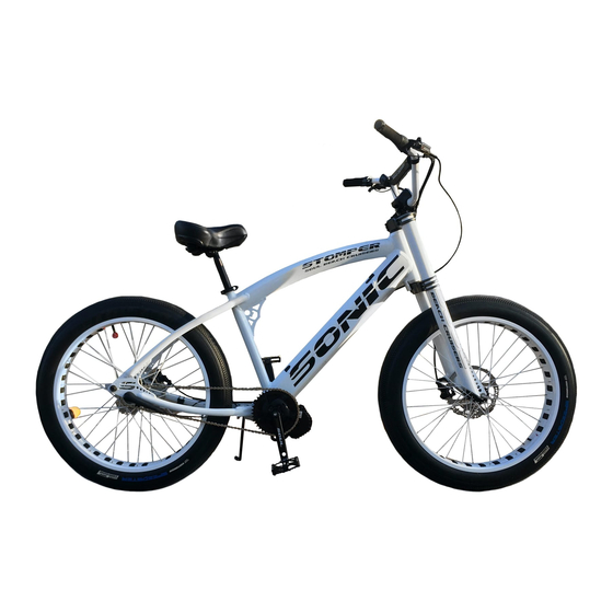
Summary of Contents for Soul Stomper
- Page 1 Assembling and Care for your new Soul Beach Cruiser...
- Page 2 Part 1: Assembly 1. Unbox and unpack your new bike. There are two to three items to look for in your bike box: 1. The bike Figure 1 The bike with standard packing 2. The main parts box - there may be a Figure 2 Contents of parts box secondary parts box dependent on model ordered...
- Page 3 Upon removal of the bike and assorted parts boxes, please remove the protective packing materials, zip ties and plastics. Take care not to cut any cables or brake hoses. Inspect for any damage during shipment. 2. Organizing the assembly - You will have the following parts/components: a.
- Page 4 Figure 4 Headset parts on right, rotor and caliper bolts left, front wheel spikes Find the fork and headset parts (optional) lower left, fender/reflector mount bolt upper left Take the black plastic lower seal and place Figure 5 Lower fork seal, shown facing up, flip over, should face down towards fork crown the rounded side down onto the headset bottom race already located on the fork...
- Page 5 The frame has some grease already in both Figure 7 Pre-installed grease races, we recommend adding a small amount of grease, if possible, to each bearing. It does not need to be packed full, just a light coating. (XTR - step not necessary) Take the 2nd ball bearing race and install it Figure 8 Bearing installed in proper orientation, add more grease if desired...
- Page 6 Take the keyed washer and put it onto the Figure 10 Keyed washer fork steerer tube. (On XTR place all black aluminum spacers onto the fork, large near bottom, thin at top) Install the lock nut on the top of the fork Figure 11 Locking nut is last to be installed, hand tighten steerer tube.
- Page 7 Figure 13 Add grease inside the fork steerer tube to allow the stem to be Apply grease into the inside of the fork, removed in the future where the stem will go to prevent rust and corrosion fusing the stem into the bike over time.
-
Page 8: Assemble The Front Wheel
Remove the bolts for the handlebar plate Figure 15 Stem with top plate removed, and bar placed Take the handlebar, and ensure the cables Figure 16 Center the bar in the stem using the knurling as a guide are not twisted, place into the stem, using the knurling as a guide to center the bar in the stem. - Page 9 Find the brake rotor and observe the two Figure 18 Rotor with stamping sides. One side has stamped letters and arrows, the other side has no stamping at all. The stamped side will face outwards away from the wheel hub. (XTR rotors have small arrows on the “spokes”...
-
Page 10: Assemble The Seat
Figure 21 Using a T25 Torx wrench, tighten bolts until they touch, then torque In either a circle or star pattern, torque each each of the bolts. (2-4 NM or 18 in pounds) If installing the optional bike spikes, remove Figure 22 Wheel installed, using spikes and axle retainer the axle nuts and begin to thread the spikes onto the axle for 2-3 turns. - Page 11 Loosen the seat clamp using a 14mm Figure 24 Seat clamp on bottom of seat wrench, to allow rotation of the seat post on the seat. Placing the saddle on a flat surface, rotate Figure 25 Adjust angle of post for basic fit up the post until it is at a 45 degree angle pointed towards the nose/front of the saddle.
-
Page 12: Install Pedals
Tighten the quick release to allow the cam Figure 27 Seat post clamp quick release shown in locked position actuation to lock the post into the frame so that it cant twist easily. (On XTR - it might be necessary to use the cam first on a lighter setting, and use a 4mm allen to add tension after moving the cam to a lock position) 7. -
Page 13: Part 2: Final Adjustment
Do the same with the left pedal Figure 29 Left hand pedal denoted with an L on pedal body Use a 15mm wrench to tighten each pedal 8. Install reflectors (US DOT safety standards recommend all bikes have reflectors) a. The white reflector is installed onto the fork. A bolt, nut and washers are included in the parts box for its installation. -
Page 14: Brake Calipers
Figure 31 Using either the fork dropout or the centerline of the tire, center the Sight through the stem to the front wheel stem and then tighten to full torque and adjust the stem for straightness. Use a 6mm allen to tighten the quill expander bolt to 11 nm or 100 inch pounds. - Page 15 Figure 34 The front brake mount bolts run through the fork into the aluminum On the front brake begin by threading in the arm that the brake rests on brake adapter arm fixing bolts into the fork and tightening to 11 nm or 100 in pounds Thread the caliper bolts in, until the caliper Figure 35 Shown top and bottom, the caliper mount bolts are not fully threaded in from the factory, begin tightening to remove some movement, but...
- Page 16 Figure 36 From the front, look through the brake comparing the brake pads to Sight through the brake, observing the the rotor, and adjusting until the gap from the rotor is the same for both pads space between the pads and the rotor. Your goal is to rotate the caliper so that there is equal space between the pads and rotor on both sides.
- Page 17 Using a 36mm headset wrench, or a large Figure 38 Thread the adjustable cup until play is reduced or not existent crescent wrench, thread the adjustable upper cone down until there is no play in the headset, but rotation of the handlebars is not under resistance.
- Page 18 With the bike flat on the ground, crouch Figure 310 Saddle after initial adjustment, nose up. down and sight across the saddle from the side of the bike. At the most, the saddle tip and rear should Figure 40 Our normal adjustment. Due to the springs, the riders weight will settle the saddle to a level adjustment be level.
- Page 19 By hand, pop the black protective cover off Figure 42 There are two adjusters under the plastic cover the adjuster area on bikes equipped with a Sturmey Archer hub. Loosen the fine tune adjuster 5- 7 turns. Figure 43 The fine tune adjuster is to the left as shown by the arrow This adjuster is threaded in quite far from the factory.
-
Page 20: Crank Adjustment
Figure 45 Use the fine tune adjuster to take up further slack until the chain With the fine tune adjuster, tighten until you moves slightly see the shifter pin chain start to move slightly. Tighten the lock nuts to finger tight and snap the protective cover back in place. Crank Adjustment Start on the drive side (with chain) crank Using a 6mm allen, tighten both bolts to... - Page 21 On the left side crank, loosen the pinch bolt first. Now, loosen the left side adjuster bolt 1 thread. With your fingers, attempt to twist the small shiny black ring between the crank arm and the bottom bracket bearing. If the ring can be moved slightly, but doesn’t spin freely, tighten the pinch bolt. Otherwise, tighten/loosen the adjuster bolt until the ring can move with mild resistance.
-
Page 22: Finishing Touches
Finishing Touches To tidy up the cables and hoses, we like to use either spiral loop tubing or zip ties. Additionally, we add small zip ties to the frame cable guides to prevent them from opening up over time. - Page 23 It is always a good idea to check the bike over from time to time for safety purposes. Your new Soul Beach Cruiser is now ready to ride. We recommend checking torque and adjustment after the first ride, and then again after 20 rides.
Need help?
Do you have a question about the Stomper and is the answer not in the manual?
Questions and answers