Table of Contents
Advertisement
Quick Links
Advertisement
Table of Contents

Summary of Contents for Munro L60iF
- Page 1 L60iF Large Volume Air Sampler Instruction Manual Munro Instruments, 44-45 Burnt Mill, Elizabeth Way, Harlow, Essex, CM20 2HU, UK Email info@munroinstruments.com Phone +44 (0) 20 8551 7000 www.munroinstruments.com Registered in England 06965050 Vat: GB 977 7939 30.
-
Page 2: Table Of Contents
L60iF Large Volume Air Sampler with Integrated Flow and Volume Display INSTRUCTION MANUAL Contents Chapter Description Page Introduction Specification Installation & Operation 3.1 Installation 3.2 Preparation for sampling 3.3 Taking a sample Technical Description Maintenance 5.1 Regular maintenance 5.2 Servicing 5.3 Fault location... - Page 3 The approach taken in the L60iF is to assume that the precise flow rate is not as important as the exact volume of air sampled, within reasonable limits, because the average flow rate is only used to calculate volume sampled.
-
Page 4: Specification
Flow and total volume - depends on the accuracy class of the rotameter flow gauge used for calibration. Initial calibration of flow rate will be 2% of reading. The user can improve on this if required. Accuracy of total measured volume will be similar to that of the flow. L60iF Issue 9 November 2018... - Page 5 Anglepoise trolley to support remote sampling head. A variety of filter papers. DC/AC Converter to enable the L60iF to operate from a 12V d.c. source in a vehicle. (Current requirement is approximately 15A) This converter is only recommended for use in a vehicle.
-
Page 6: Installation & Operation
3. Installation and operation 3.1 Installation The L60iF is a portable instrument with a permanently connected mains cable. Unless otherwise marked, it is designed to operate from a 110V 50Hz supply. The power cable uses the standard colour code of Live - Brown;... - Page 7 HF appended. If a limit less than 1 l/min is attempted, the high alarm will be disabled. Alarm Sounder The audible alarm that sounds when a flow failure is recorded can be muted. L60iF Issue 9 November 2018...
- Page 8 This mode will be entered as soon as the operator selects Run test and then confirm to start the test. The test will run until stop is selected by the operator. Flow, total volume and elapsed time will be displayed during the test. L60iF Issue 9 November 2018...
- Page 9 All media must be handled carefully to avoid loss of particulate and to maintain traceability. Used filters should be analysed as soon as possible. 3.2.3 Leaving supervisory mode To revert to operator mode, switch the sampler off and on again after five seconds. L60iF Issue 9 November 2018...
-
Page 10: Taking A Sample
LF – Sample ended by low flow alarm (will not resume) HF – Sample ended by high flow alarm (will not resume) TL – sample time reached 10,000 hours. Sample ended. OV – sample volume reached 10,000 m³. Sample ended L60iF Issue 9 November 2018... -
Page 11: Technical Description
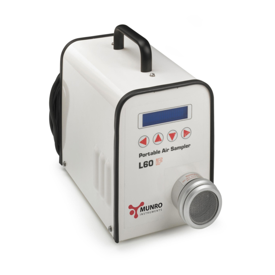
4. Technical Description The L60iF is a large volume air sampler with a nominal sampling rate of 60 litres per minute. It uses a standard Munro Instruments Pump and Motor unit to draw air through a 60mm open face filter holder. -
Page 12: Maintenance
Sampler is in constant use. If servicing is to be carried out locally, a course is available from Munro Instruments on Large Volume Air Sampler maintenance and servicing, which includes stripping down and re-assembly of pumps, checking blade dimensions and making performance measurements. -
Page 13: Re-Calibration
Notes on accuracy The accuracy of the flow indication of the L60iF will be almost as good, (but not quite) as the flowmeter used to calibrate it. Consider a flow gauge with a full-scale reading of 100 litre/minute, the most likely range for calibrating the L60iF. -
Page 14: Basic Calibration
60mm filter holder. Unscrew the filter holder and locate the cone adapter in its place using its locking ring. 6.1.2. Connect the flow gauge to the L60iF via the Restriction Valve (see diagram above). Open the valve to offer minimum restriction. -
Page 15: Temperature Compensation
6.1.3. With the L60iF switched OFF, press and hold the right ( ) and left ( ) arrows on the front panel while switching on the power. This will force the L60iF into Calibration mode. The motor will start in order to warm it up ready for calibration. - Page 16 6.2.3. With the L60iF switched OFF, press and hold the right ( ) and left ( ) arrows on the front panel while switching on the power. This will force the L60iF into Calibration mode. The motor will start in order to warm it up ready for calibration.
-
Page 17: Order Codes
These can be at our premises or on site, and may be of particular interest to users who cannot easily return samplers to Munro Instruments for servicing and re-calibration. Courses can be at user level, including first line servicing or at a more advanced level, including stripping down and resetting of pumps, testing and recalibration. -
Page 18: Diagnostic Mode
3. To assist in fault finding. 8.1 Accessing Diagnostics Mode With the L60iF powered down, press and hold the ( ) and ( ) buttons while powering p. An opening screen reading L60iF Diagnostics and the version number is briefly displayed, changing to... - Page 19 It can be seen from the above typical figures that there is a difference of nearly 4 l/min between true and L60iF measured flow when the pump is cold, and only a small residual difference of 0.3 l/min when the pump is hot.
- Page 20 By restricting the flow to one of the set points the corresponding ADC value should be indicated. Temperature 40.2 C 63.1 l/min ADC 254.0 An indicated flow rate of 00.0 l/min indicates an invalid calibration. Press ( ) or ( ) to stop the pump. L60iF Issue 9 November 2018...
-
Page 21: A1.1 Temperature Compensation
This is what would be expected since at the beginning of the test, when the temperature was 13°C, the true (Flow Gauge) reading was 71 l/min and the L60iF internal reading was 74.7l/min. The small error of 0.3l/min is negligible, and is caused by the assumption that the error is linear with temperature change. The true variation is slightly non-linear. -
Page 22: A1.2 Accuracy Of Reading
The temperature calibration uses a highly accurate sensor as the primary temperature reference, whose output is accurate to ±0.5°C. The L60iF assumes that the error in flow reading is linear with temperature, an assumption justified by tests. The flow indication is ±0.5 litre/minute over the working range of approximately 50- to 65 litre/minute. -
Page 23: A1.3 Changing The Eprom
9. Insert the Eprom, ensure that the notch is away from the edge of the board and that no pins are bent. 10. Press home firmly. 11. Replace the lid of the case. 12. Apply power. The Version should now read the updated value. L60iF Issue 9 November 2018... - Page 27 Taking flow reading Please wait 9.9 sec Temperature Cal Temperature Cal req? Cold flow rate 70.0 Hot flow rate 65.0 adjust Save adjust Save Calibration data stored Opening display 10:30 Fri 14/04/2000 last test run test L60iF Issue 8 July 2014...
- Page 28 Issue 5 Calibration diagram and following paragraph amended. An inline filter is not now used in calibration. This modification record added. Issue 6 Amendments reflecting new ownership Issue 7 Auto Resume. Higher maximum values. Firmware V1.04 Issue 8 Safety warning for fan filter change Issue 9 Address details updated L60iF Issue 8 July 2014...
Need help?
Do you have a question about the L60iF and is the answer not in the manual?
Questions and answers