
Related Manuals for Armstrong ABH 299

Summary of Contents for Armstrong ABH 299
- Page 1 Armstrong High Efficiency Water Heaters And Heating Boilers Installation & Operations Manual Please read and save these instructions HW-400-EN V2.6...
-
Page 2: General Safety Guidelines
Safety Icon Legend — DANGER! … Injury or death and property damage are imminent — WARNING! … Injury or death and property damage are possible — CAUTION! … Potential property damage, expensive repairs, and/or voiding the equipment warranty may result BURN HAZARD! Contact with steam, hot water, or hot metal surfaces can cause severe skin burns. - Page 3 Warning and Cautions Do not store or use gasoline or other flammable vapors and liquids in the vicinity of this or any other appliance. WHAT TO DO IF YOU SMELL GAS: • Do not try to light any appliance • Do not touch any electrical switch •...
-
Page 4: Table Of Contents
Table Of Contents Safety ..................2 Icon Legend ........................2 General Safety Guidelines: ..............2 General Information .................6 How It Operates ......................6 ABH Hot Controls Special Section .................7 Glossary .........................8 ABH Dimensions ......................9 Pre-Installation Requirements ..................10 Pressure Relief Valve ....................11 ELECTRICAL ................12 Electrical Connection / Requirements ................12 Internal Wiring Connection ...................12 Gas Connection ................ - Page 5 Start-Up Procedures ............... 36 Items To Be Checked Before Lighting The ABH ............36 Lighting Instructions ......................36 Operating Instructions ....................37 Adjusting The Temperature On The ABH Display ............37 Sequence Of Operation ....................37 0–10V Direct Control ....................38 Servicing ..................40 Servicing The ABH .......................40 Placing The ABH Into Normal Operation ..............40 ABH Hot™...
-
Page 6: General Information
General Information How It Operates The ABH product line is an extremely high efficiency water heating product, requiring special venting and condensate removal precautions. All high efficiency condensing appliances will require more maintenance (cleaning) than their non-condensing counterparts. Failure to do so may result in damage to the appliance that is not covered under warranty. Failure to follow all of the instructions contained in this manual may also cause premature product failure that may not be covered under warranty. -
Page 7: Abh Hot Controls Special Section
General Information - continued ABH Hot Controls Special Section BCB—Boiler Control Board BDB—Boiler Display Board CCB – Cascade Control Board CDB - Cascade Display Board EDB – Eeprom Data Board – contains all operating parameters of CCB and BCB Designs, materials, weights and performance ratings are approximate and subject to change without notice. Visit armstronginternational.com for up-to-date information. North America •... -
Page 8: Glossary
General Information - continued Glossary Air pressure switch Interface Cascade Manager (with or without WiFi) Indirect Tank Boiler Control Board Sanitary hot water tank with a built in heat exchanger Boiler Display Board Baseline data initialization, runs by default every 14 days Blocking Lead-Lag System Limit situation is touched, boiler OFF;... -
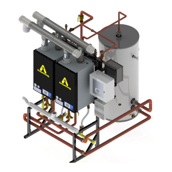
Page 9: Abh Dimensions
Condensate Trap Cleaning Point Condensate Waste Condensate Waste Condensate Waste Condensate Waste Inlet (B) Gas (D) Table 1.1 ABH Dimensions Width Height Depth Model ABH 299 18.9 44.9 1140 19.3 ABH 399 18.9 45.2 1148 19.3 ABH 599 18.9 47.2 1199 Table 1.2 ABH Information... -
Page 10: Pre-Installation Requirements
• PH—below 6.5 or above 7.5 For total combined hardness over 15 grains (250 ppm or mg/l) or longer pipe lengths, contact Armstrong Hot Water, Inc. for correct pump sizing. Combined, the hardness and TDS can be no more than 450 ppm. Our internal term for this is the TCH (Total Combined Hardness). -
Page 11: Pressure Relief Valve
A water heating appliance should always be located in an area with a floor drain or installed in a drain pan suitable for water heating appliances. Under no circumstances, shall Armstrong Hot Water, Inc. be held liable for any such water damage whatsoever. -
Page 12: Electrical
Electrical Electrical Connection / Requirements The electrical connection for the ABH is on the bottom of the unit. There is a 1/2” knockout location for an electrical connection for the heater’s incoming power connection. All electrical wiring must be performed by a qualified licensed electrician in accordance with National Electrical Code ANSI/NFPA and/or the Canadian Electrical Code, Part 1 CSA C22.1, or to any applicable local codes and standards. - Page 13 Electrical - continued EVO Appliance Wiring w/HOT Controls HW299.2-HW599.2 Cover page REVISION 11/15/2017 Brian Updated wire colors & AWG 10/10/2017 Brian REV. DATE NAME CHANGES SCHEME User data 2 LOCATION: Main Panel CONTRACT N° : Document created with version : 2016.0.0.114 Figure 2.1 Field Wiring Connections A.
-
Page 14: Gas Connection
Gas Connection Gas Connection DANGER! Failure to follow all precautions could result in fire, explosion or death! The gas supply shall have a maximum inlet pressure of less than 14” water column (1/2 PSI) (3.44 kPa), and a minimum of 4” water column. -
Page 15: Gas Tables
Gas Connection - Continued Gas Tables TABLE 3.1 Natural Gas Supply Piping Nominal Internal Length of Pipe - Feet (Meter) Iron Pipe Diameter Size (in.) (inches) (12) (15) (21) (24) (27) (30) (38) (46) (61) 0.824 (106.4) (73) (58.6) (50.1) (44.5) (40.4) (37.2) -
Page 16: Gas Valve Setup
Gas Connection - Continued Gas Valve Setup Figure 3.2 - ABH Models 299–399 Figure 3.3 - ABH Model 599 See Start-Up Procedures Section (page 36) Before Continuing Proper gas volume and pressure is critical to the operation of any high efficiency appliance. There are three types of measurements that must be taken to provide the data to insure product performance: •... - Page 17 Gas Connection - Continued Figure 3.4 - Gas Pressure Testing Points Gas Pressure Gas Pressure Gas Pressure Test Point Test Point Test Point Table 3.3 Combustion & Fuel Related Adjustment Table Natural Gas CO Natural Gas CO ppm LP Gas CO LP Gas CO ppm Approximate, do not use for setup! Approximate, do not use for setup!
-
Page 18: Setting The Maximum Load
Gas Connection - Continued Setting The Maximum Load A means of sampling the leaving flue gas is built into the vent connector on top of the appliance. Remove the rubber plug for testing and replace when testing is completed. This plug MUST be in place during normal operation. Enter the service function from the setup menu. -
Page 19: Gas Valve Maintenance/Replacement
Gas Connection - Continued Gas Valve Maintenance/Replacement 1. When checking or replacing a gas valve, the CO percentage in the flue gas is the preferred measuring method to insure proper combustion and firing rate. CO is used as the alternate. 2. -
Page 20: Venting
6' (1.8) + (2) 90º elbows 200' (51) *The use of 6" PVC will require the purchase of aspecial adapter from Armstrong Hot Water, Inc. Designs, materials, weights and performance ratings are approximate and subject to change without notice. Visit armstronginternational.com for up-to-date information. - Page 21 Do not combine the inlet air or exhaust with any other inlet or exhaust pipe including either to an additional similar appliance, unless you have purchased an engineered Common Venting System from Armstrong Hot Water, Inc. The joints must be properly cleaned, primed and cemented if plastic, and sealed per the manufacturer’s instructions if stainless.
- Page 22 Venting - continued Figure 4.1 *NOTE: Armstrong Hot Water, Inc. recommends a minimum clearance of 4 feet (1.2m) where the exhaust plume caused by the unit may obstruct views or affect the cosmetic look of the building. In canada, there is a minimum clearance of 10 feet (3m).
- Page 23 Venting - continued Figure 4.2 - Sidewall Vent With Down Elbow (Intake) & Up Elbow (Exhaust) VENTING FOR MULTIPLE UNITS, 1/4" ft. slope to appliance Exterior wall with vents all on same horizontal plane, All horizontal runs must spaced at least 8 inches apart, and at be supported every 24"...
- Page 24 Venting - continued Figure 4.4 - Vertical Vent With PVC/CPVC 18" min.(457mm) 24" max. (609mm) Exhaust w/coupler & bird screen 24" (609mm) or Min. 12" (305mm) 12" (305mm) above above parapet wall Air intake 90˚ elbow w/bird screen maximum snow level, if withing 10' wall whichever is greater 8"...
- Page 25 Venting - continued Diagrams For Room Air Venting Termination If you’re using room air, your unit should be set up this way: CAUTION! Flue Gas will condense as it exits the vent termination. This condensate can freeze on exterior building surfaces which may cause discoloration of these surfaces. Consideration should be given to the plume of condensation that exits the exhaust which may affect the cosmetic appearance of the building.
-
Page 26: Inlet Air Vent
If the combined venting length of a heater’s exhaust/inlet air system exceeds the Maximum Combined Length called out in Table 4.1 contact Armstrong Hot Water, Inc. for an engineered venting calculation. Do not proceed without calling Armstrong Hot Water, Inc. -
Page 27: Condensate Requirements
CONDENSATE DRAIN FROM HEAT EXCHANGER a suitable inside drain. A condensate neutralizer and a CONDENSATE HOSE condensate pump kit are available from Armstrong Hot FROM AIR INLET HOSE CLIP Water, Inc. It is also very important that the condensate HOSE CLIP... -
Page 28: Piping
Basic piping connection steps are listed below. A drawing, specific to your application can be obtained from your distributor or Armstrong Hot Water, Inc., which will guide you through proper installation of the ABH. 1. Pipe properly, in accordance with generally accepted piping principals or Armstrong Hot Water, Inc. specific documents. -
Page 29: Boiler Schematic Drawings
Gas cock System Separator Floor Drain Boiler Schematic Drawings Drain Valve Temperature Sensor Air Vent Boiler pump Two Boiler Schematic To Armstrong System Separator Temperature & Ball Valve with built-in Pressure gauge Check Valve LEGEND Hot Water Supply Thermometer Make-up... -
Page 30: Fill & Purge Heating System
Removing Air From The Heat Exchanger The ABH 299–599 has an automatic air vent on the top of the appliance and the air vent cap must be loosened to allow trapped air to escape when the appliance is initially filled and put into operation. If this air vent should start to leak, there are two possible solutions: •... -
Page 31: Water Heating Piping
3. Isolation valves should be installed on each heater and on the cold and hot water system connections. Upon completion of piping, fill and properly purge of all air. Open all valves and start circulating pump. Consult Armstrong Hot Water, Inc. -
Page 32: Water Heating Schematic Drawings
Piping - continued Water Heating Schematic Drawings LEGEND LEGEND Hot Water Supply Thermometer One Water Heater Schematic To Single Tank Hot Water Return Pump From System Cold Water Ball valve To System Condensate Drain Check valve Water Heater with Stand Aquastat Storage Tank Flow direction... - Page 33 Piping - continued One Water Heater Schematic To Single Tank With Mixing Valve And CWIS ™ From System To System LEGEND Hot Water Supply Hot Water Return Cold Water Tempered Water Supply Tempered Water Return Condensate Drain Water Heater with Stand Make-up Storage Tank Water...
- Page 34 Piping - continued Three Water Heater Schematic To Single Tank From System To System LEGEND Hot Water Supply Hot Water Return Cold Water Condensate Drain Water Heater with Stand Make-up Storage Tank Water Expansion Tank Condensate Neutralizer Thermometer Pump Ball valve Check valve WH-1 WH-2...
- Page 35 Piping - continued Three Water Heater Schematic To Single Tank With Mixing Valve And CWIS ™ LEGEND Ball Valve Hot Water Supply Check Valve Hot Water Return Cold Water Aquastat Flow Direction From System To System Tempered Water Supply Pressure Relief Valve Tempered Water Return Ball Valve with Built-in Drain Condensate Drain Water...
- Page 36 Piping - continued Three Water Heater Schematic To Two Tanks LEGEND Hot Water Supply Thermometer To System Hot Water Return Pump Cold Water Ball valve From System Condensate Drain Check valve Water Heater with Stand Aquastat Storage Tank Flow direction Expansion Tank Pressure Relief valve Condensate Neutralizer...
-
Page 37: Start-Up Procedures
Start-Up Procedures Items To Be Checked Before Lighting The ABH It is recommended that you read the General Information Section (page 6-11) to get a better understanding of how the ABH operates before you start the unit and use the Start-Up Checklist as a check and to document and confirm all conditions are correct. All ABH start ups should be conducted by properly qualified professionals. -
Page 38: Operating Instructions
50–195°F for boilers. Other special ranges are available by contacting the factory. If other temperature settings are required, contact Armstrong Hot Water, Inc. Other special parameters may be set by entering a password in the display, varying from end user, installer, advanced, and factory levels. -
Page 39: 0-10V Direct Control
Start-Up Procedures - continued 6. When the post-purge is complete, the control enters an idle state while continuing to monitor temperature and the state of other system devices. If a call-for-heat is received, the control will automatically return to Step 2 in sequence and repeat the entire operating cycle. - Page 40 Start-Up Procedures - continued The following is an example of the effect of changing the voltage signal on an appliance in Load Control mode: • The operational range of a 399.x fan is 25%–100% • 0-0.9V = Appliance off • 1.0V = 25% Fan speed •...
-
Page 41: Servicing
Servicing Servicing The ABH 1. Shut off the power supply to the appliance (See Figure 1.4, page 11). 2. Remove the front cover security screw(s). 3. Undo the two latches at the bottom of the cover (if applicable). 4. Remove the cover. Placing The ABH Into Normal Operation 1. - Page 42 Servicing - continued *Codes may appear with an A, B, or C as a suffix denoting the number of times the code has appeared since the last Initialization (INI). Some SLO’s are accompanied by a reduction of the maximum firing rate; A=80%, B=50%, C=30%. After the C suffix appears, the next code of that kind becomes an HLO (manual reset required).
- Page 43 Servicing - continued Table 7.2 BCB Soft Lock Out (SLO) Codes - Continued Code Cause Recommended Action Reset the fault, cycle power on and off, if the fault reappears, the EMB–EEPROM is ID03 EMB EEPROM fault (1) corrupted. Reset the fault, cycle power on and off, if the fault reappears, the EMB–EEPROM is ID04 Internal fault (gv1) corrupted.
-
Page 44: Abh Hot™ Controls Hard Lockout Codes
Servicing - continued ABH Hot™ Controls Hard Lockout Codes Table 7.3 BCB Hard Lockout (HLO) Codes Code Cause Recommended Action Excessive pressure differential (∆P) on water side of heat Check for scaling or blockage on water side of heat exchanger, also check pump A1/A2 exchanger performance. -
Page 45: To Turn Off Gas To The Appliance
Servicing - continued Table 7.3 BCB Hard Lockout (HLO) Codes - continued Table 7.3 BCB Hard Lockout (HLO) Codes - continued Code Cause Recommended Action Appliance has been through multiple tests and checks including trying to ignite IG2/IG3 Too many restarts or relights after no-flame. at different inputs to avoid this shut down. -
Page 46: Status Readings
Servicing - continued Status Readings Figure 7.4 - Status Reading Instructions Sensor list and other details on screens will vary from system to system. ABH Sensor Resistance Table Table 7.5 ABH Sensor Resistance Table Temperature ( Resistance (Ohm) Temperature ( Resistance (Ohm) 32550 32550... -
Page 47: Maintenance
Maintenance Periodic Maintenance of Heater and Inspections All high efficiency condensing appliances will require more regular maintenance (cleaning) than their non-condensing counterparts. Failure to do so may result in damage to the appliance that is not covered under warranty. Failure to follow all of the instructions contained in this manual may also cause premature product failure that may not be covered under warranty. - Page 48 Maintenance - continued • Remove and inspect the rear fiberboard. If any resistance is encountered with the removal of the screw securing the fiberboard in place, do not exert undo force; break the fiberboard out to provide access to the screw. Apply penetrating oil to the screw, let it sit, then remove.
- Page 49 Maintenance - continued • Check the distance from the electrode to the burner; there should be a 3/8" gap in between the two. If the existing electrode pins must be adjusted for proper gap, caution must be exercised, as they will likely be brittle from exposure to the flame;...
- Page 50 Maintenance - continued Testing The following steps require the power supply be turned back on; extreme caution must be exercised when performing service with the power supply on and the door off. • When turning the appliance back on, listen for significant noises from the fan and pump. Also, inspect for leaks at the pump connections.
- Page 51 Maintenance - continued Try to keep the measuring hose flat with the inner wall of the pipe. Use a small opening to insure you are measuring static pressure and not velocity pressure P (1, 2, 3) A These will be negative pressures relative to atmosphere P (1, 2, 3) F These will be positive pressures relative to atmosphere Example...
-
Page 52: Condensate Trap Cleaning Instructions
Maintenance - continued Condensate Trap Cleaning Instructions The condensate trap and entire drain system attached to it (above the neutralizer) should be cleaned at least once every year. 1. Turn off the power to the ABH. 2. Place a bucket under the condensate trap. Use caution when removing the clean-out cap, as the trap is full of condensate and it may be hot. -
Page 53: Combustion Chamber Coil Cleaning Instructions
Maintenance - continued Combustion Chamber Coil Cleaning Instructions* *Before beginning this procedure, you must have the following items on hand: • Nylon brush - DO NOT use brass, stainless or steel brushes. • Water • Vacuum cleaner • Fernox F3 Cleaner •... - Page 54 Maintenance - continued Water Side Cleaning (de-scaling kit is required for this process, please consult factory) 1. Shut down the ABH and clean by using the following steps for heaters: - Turn off the power, close the gas valve, and shut down the unit. Wait for the unit to be cool to the touch.
-
Page 55: Abh Controls
Maintenance - continued ABH Controls DANGER! It is extremely important that you check for leaks when reconnecting the gas valve and make sure the exhaust vent is no longer blocked. Failure to do so may result in severe personal injury or death. The following components are found on the control panel on the front of the appliance. -
Page 56: Boiler Control Board (Bcb) Screens
Maintenance - continued BOILER CONTROL BOARD (BCB) SCREENS In the main screen it is possible to see: • Hamilton logo • Set point value • Type of system (icons) • Date and time • Labels for navigation through the controller (STATUS, SET POINT, HISTORY, SETUP) •... - Page 57 Maintenance - continued In case of fault indication (SLO or HLO), the main page shows the code of the fault occurred. To see the extended description you have to go into HISTORY menu, where a new item “ACTUAL FAULT” will be displayed. In case a boiler RESET is required (HLO fault), it is possible to activate the RESET procedure entering the ACTIVE FAULT page and selecting the corresponding item.
- Page 58 Maintenance - continued NOTE: the behavior described is referred to the BCB board not working as a cascade module. So, the only possible configuration modes are the following: only central heating, central heating with Indirect hot water, direct hot water. Depending on the active configuration, the corresponding items will be displayed.
-
Page 59: Coil Anti-Scaling Prevention Feature
Maintenance - continued The procedure to access the parameters is as follows: while in STANDBY mode, in SETUP page, or in HISTORY page, press DOWN and BACK keys at the same time for about 5 seconds. The passwords are as follows: Level 0= USER (No password needed) Level 1= INSTALLER EAZ1LVL... -
Page 60: Special Installation Requirements
• By adjusting the combustion characteristics as described above, there is no de-rate required at altitudes up to 19,000 feet. For elevations in excess of 19,000 feet or gas BTU content levels below 950 BTU/cubic foot, consult the Armstrong Hot Water, Inc. for adjustments and de-rating information. -
Page 61: Parts Breakdown
Parts Breakdown Designs, materials, weights and performance ratings are approximate and subject to change without notice. Visit armstronginternational.com for up-to-date information. North America • Latin America • India • Europe / Middle East / Africa • China • Pacific Rim armstronginternational.com... - Page 62 Parts Breakdown - continued Table X.X ABH Parts Breakdown Item# Part Description Part Number PANEL FRONT DOOR ABH299-399HOT ASSY W/BEVEL WIN D116957 DOOR ASSY ABH599HOT FLAT WINDOW D109348 BURNER INL HW599 AIR/GAS D105610 PILOT SPARK ELECTRODE ASSEMBLY 79-599 KNURLED PLT 94318 A GASKET 3-5/16 OD EPDM 60 DURO TUBE/BURNER D104184 BURNER DOOR HW79-599...
- Page 63 Parts Breakdown - continued Table X.X ABH Parts Breakdown - continued Item# Part Description Part Number PANEL BTM 20GA CS 1010-1020 HW299-399 POWDER COAT D113884 PANEL SHEET METAL BOTTOM ASSEMBLY 299-399 JKB 94102 B PANEL BTM 18GA CS A1008 TB HW599HOT PWDR COAT D108482 PANEL BTM ASSY HW599HOT D109370...
- Page 64 Parts Breakdown - continued Table X.X ABH Parts Breakdown - continued Item# Part Description Part Number SWITCH FLOW 1/2 MNPT 1.09 V-10 FLAT PADDLE ABH399-599SIT (HW599.3 ONLY) D114073 TRANSDUCER PRESS 1/8 MNPT 0-150 PSIG (HW599.2 QTY=2X, HW599.3 QTY=1X) D104961 ARM OUT ABH599 D104575 ARM INLET HW599 HC D104574...
-
Page 65: Appendix - Additional Electrical Drawings
Appendix - Additional Electrical Drawings Main Power & Relay Assembly and Cascade Wiring for ABH Designs, materials, weights and performance ratings are approximate and subject to change without notice. Visit armstronginternational.com for up-to-date information. North America • Latin America • India • Europe / Middle East / Africa • China • Pacific Rim armstronginternational.com... - Page 66 Appendix - Additional Electrical Drawings - continued Main Power & Relay Assembly POWER TO PUMP MAIN POWER GAS VALVE RELAY PUMP RELAY Designs, materials, weights and performance ratings are approximate and subject to change without notice. Visit armstronginternational.com for up-to-date information. North America •...
- Page 67 Appendix - Additional Electrical Drawings - continued Cascade Box with 3G Router Designs, materials, weights and performance ratings are approximate and subject to change without notice. Visit armstronginternational.com for up-to-date information. North America • Latin America • India • Europe / Middle East / Africa • China • Pacific Rim armstronginternational.com...
- Page 68 Notes Designs, materials, weights and performance ratings are approximate and subject to change without notice. Visit armstronginternational.com for up-to-date information. North America • Latin America • India • Europe / Middle East / Africa • China • Pacific Rim armstronginternational.com...
- Page 69 Notes Designs, materials, weights and performance ratings are approximate and subject to change without notice. Visit armstronginternational.com for up-to-date information. North America • Latin America • India • Europe / Middle East / Africa • China • Pacific Rim armstronginternational.com...
- Page 70 Notes Designs, materials, weights and performance ratings are approximate and subject to change without notice. Visit armstronginternational.com for up-to-date information. North America • Latin America • India • Europe / Middle East / Africa • China • Pacific Rim armstronginternational.com...
-
Page 71: Limited Warranty And Remedy
Armstrong, however caused, and whether such claim is based upon warranty, contract, negligence, strict liability, or any other basis or theory, is limited to Armstrong’s repair or replacement of the product, or, at Armstrong’s discretion, refund of the purchase price. - Page 72 At the time a claim is filed, the purchaser must present a copy of the original sales receipt or the invoice number on which the appliance was purchased from Armstrong. If, at the time of a request for service the purchaser can not provide a copy of the of the original sales receipt or the warranty card registration, the warranty period for the product shall the be deemed to have commenced thirty (30) days after the date of manufacture (based on the product serial number) and NOT the date of installation.
Need help?
Do you have a question about the ABH 299 and is the answer not in the manual?
Questions and answers