
Subscribe to Our Youtube Channel
Related Manuals for Spectris Arcom APOLLO

Summary of Contents for Spectris Arcom APOLLO
- Page 1 APOLLO Intel Celeron M/Pentium M based EBX Single Board Computer Technical Manual company www.arcom.com...
- Page 2 Issue A V1I3 27 April 2005 Release of short form manual. © 2005 Arcom. Arcom is a subsidiary of Spectris plc. For contact details, see page 47. Arcom operates a company-wide quality management system which has been certified by the...
-
Page 3: Table Of Contents
APOLLO Technical Manual Contents Contents Introduction ............................4 APOLLO ‘at a glance’ ......................5 Features..........................7 Support products........................9 Development kits .........................10 Handling your board safely ....................11 Conventions .........................12 Getting started with your APOLLO ....................13 CPU configuration........................13 Installing memory.........................13 Installing a processor ......................14 Connecting a floppy disk drive .....................15 Connecting a hard disk drive ....................15 Connecting a CD-ROM (IDE Type) ..................15 Connecting a CompactFlash card..................16... -
Page 4: Introduction
APOLLO Technical Manual Introduction Introduction The APOLLO is an EBX format, high-performance, high-functionality PC-compatible processor board designed for embedding into OEM equipment. The board is based on the Intel 855GME/ICH4 chipset and supports a range of Intel Pentium M and Celeron M mobile processors to offer a combination of high performance computing features with low power dissipation. -
Page 5: Apollo 'At A Glance
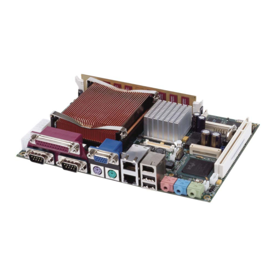
APOLLO Technical Manual Introduction APOLLO ‘at a glance’ ATX power supply connector COM4 RS485/RS422 serial port IrDA connector System and CPU fans Front panel interface Primary IDE interface LVDS display interface COM3/COM4 RS232 serial ports LCD backlight connector Firewire port 1 System control interface 3 stereo audio jacks... - Page 6 APOLLO Technical Manual Introduction VGA CRT Firewire Line Out Parallel port Primary LAN Mic In COM1 Keyboard Secondary LAN USB1 Line In COM2 Mouse USB2 Side view showing connectors © 2005 Arcom Issue A...
-
Page 7: Features
APOLLO Technical Manual Introduction Features Processor • Intel Pentium M and Celeron M processor options. Chipset • North Bridge: Intel 82555GME. • South Bridge: Intel 82801DB/ICH4. • 400MHz processor side bus speed. System memory • Up to 1024MB PC2700 DDR DIMM. BIOS •... - Page 8 APOLLO Technical Manual Introduction Other ports, connectors and sockets • Printer, mouse, keyboard and floppy drive ports. (Slimline floppy via flat flex connector.) • Auxiliary connector for LCD character display, GPIO, LED drivers and SMBus. • Two IEEE1394a-2000 Firewire ports (100/200/400Mbps). •...
-
Page 9: Support Products
APOLLO Technical Manual Introduction Support products The APOLLO is supported by the following optional products: • 1U 19" wide APOLLO ICE (Industrial Compact Enclosure) Provides easy-to-use system solutions for embedded SBC applications. It is manufactured from 0.9mm (20 SWG) finished mild steel. The enclosure conforms to the 19"... -
Page 10: Development Kits
APOLLO Technical Manual Introduction Development kits Arcom offers development kits for the APOLLO board. A choice of three different configurations is available: • Windows XP Embedded contained on 1GB CompactFlash card. • Windows XP Professional Edition contained on 2.5" 40GB IDE HDD. •... -
Page 11: Handling Your Board Safely
APOLLO Technical Manual Introduction Handling your board safely Anti-static handling This board contains CMOS devices that could be damaged in the event of static electricity being discharged through them. At all times, please observe anti-static precautions when handling the board. This includes storing the board in appropriate anti-static packaging and wearing a wrist strap when handling the board. -
Page 12: Conventions
APOLLO Technical Manual Introduction Conventions The following symbols are used in this guide: Symbol Explanation Note - information that requires your attention. Tip - a handy hint that may provide a useful alternative or save time. Caution – proceeding with a course of action may damage your equipment or result in loss of data. -
Page 13: Getting Started With Your Apollo
APOLLO Technical Manual Getting started with your APOLLO Getting started with your APOLLO Once you have a working APOLLO system, you can start adding other peripherals to enable you to start development. In this section we guide you through setting up and using peripherals and some of the features of the APOLLO. -
Page 14: Installing A Processor
APOLLO Technical Manual Getting started with your APOLLO Installing a processor The standard and Gigabit variants of the APOLLO board have a zero insertion force PGA socket soldered to the board that accepts a range of Pentium M and Celeron M µFC-PGA processors. -
Page 15: Connecting A Floppy Disk Drive
APOLLO Technical Manual Getting started with your APOLLO Mount a suitable cooling solution to contact the exposed processor die before the board is powered on. The BIOS automatically determines the processor installed and adjusts the settings accordingly. No BIOS modifications are required. Connecting a floppy disk drive The APOLLO supports one slimline floppy drive via a flat flex connector. -
Page 16: Connecting A Compactflash Card
APOLLO Technical Manual Getting started with your APOLLO Connecting a CompactFlash card The APOLLO has a single CF+ version 2.0 Type II CompactFlash socket that supports both Type I and Type II CompactFlash cards. This provides support for magnetic disk drive data storage and I/O cards such as Ethernet, serial, fax/modem, barcode scanner, Bluetooth, 802.11b wireless LAN, wireless digital cell phone cards, and so on. -
Page 17: Connecting A Printer
APOLLO Technical Manual Getting started with your APOLLO Connections to COM1 and COM2 are via standard DB9 connectors. COM3 and COM4 are interfaced via a 10-way boxed header. The pin assignment of these headers is arranged to enable a 9-way IDC D-Type plug to be connected directly to pins 1-9 on the cable. -
Page 18: Using The 1394 Ports
APOLLO Technical Manual Getting started with your APOLLO Two LEDs on each RJ-45 port provide information about its operation, as follows: • The LED on the left (as you look at the connector) tells you about the speed the port is currently operating at. -
Page 19: Jumpers And Connectors
APOLLO Technical Manual Jumpers and connectors Jumpers and connectors The following diagrams show the jumpers and connectors on the APOLLO. Click on any jumper or connector name for information. © 2005 Arcom Issue A... - Page 20 APOLLO Technical Manual Jumpers and connectors © 2005 Arcom Issue A...
-
Page 21: Jumpers
APOLLO Technical Manual Jumpers and connectors Jumpers There are three jumpers on the APOLLO with a total of eight user-selectable jumper positions. These are summarized in the following table: Jumper Description Performs two functions: • PCI Grant/PCI Auxiliary power selection. •... - Page 22 APOLLO Technical Manual Jumpers and connectors JP1 PCI – PCI Grant/PCI Auxiliary power selection Used to select the functionality of PCI slot pin A14. There are two options available. These are 3.3V PCI auxiliary voltage routed to the PCI slot or GNT4 routed. GNT4 is made available to support a third PCI slot (via a riser card).
- Page 23 APOLLO Technical Manual Jumpers and connectors USR1 – User-defined jumper 1 This jumper is user-configurable and can be used by an application program to signify a configuration setting. The status of this jumper is read through the firmware hub general purpose inputs, located at memory location FFBC0100H bit 1.
- Page 24 APOLLO Technical Manual Jumpers and connectors This position is used with the APOLLO TPM option to provide a tamper detect facility. Further information about the operation of this function will be made available in future updates. JP3 – RS485/422 configuration This jumper is used to configure the RS485/422 serial interface.
-
Page 25: Connectors
APOLLO Technical Manual Jumpers and connectors Connectors There are 34 connectors on the APOLLO that let you connect external devices such as keyboards, floppy disk drives, hard disk drives, printers etc. Connector Function See … ATX power connector. Page 26. Audio Line Out. - Page 26 APOLLO Technical Manual Jumpers and connectors Connector Function See … Primary LAN. Page 41. Secondary LAN. Page 41. CompactFlash socket. Page 42. PCI slot. Page 43. Video option and USB ports 5/6 Page 44. connector. CPU fan. Page 46. 184-pin DDR SDRAM DIMM socket. System fan.
- Page 27 APOLLO Technical Manual Jumpers and connectors J1, J2, J3 – Audio connectors 3.5mm stereo audio jacks are used for audio connection. The audio codec can operate in either of the following modes: • 2.1 mode, which allows for microphone in, line in and line out operation. •...
- Page 28 APOLLO Technical Manual Jumpers and connectors J2 - 3.5mm audio jack PC99 Colour: light blue Signal name 2.1 mode 5.1 mode Line in left Rear surround left Ring Line in right Rear surround right Sleeve Ground Ground J3 - 3.5mm audio jack PC99 Colour: pink Signal name 2.1 mode...
- Page 29 APOLLO Technical Manual Jumpers and connectors J8 – S/PDIF digital output 3-way 2mm pitch shrouded header. Mating connector: JST PHR-3 Mating connector crimps: JST SPH-004T-P0.5S Signal name S/PDIF Output to optical transmitter J4A – IEEE1394 connector port 0 6-pin IEEE1394 connector. Signal name +12V (Fused) Ground...
- Page 30 APOLLO Technical Manual Jumpers and connectors J19 – IEEE1394 connector port 1 10-way, 2.54mm (0.1") x 2.54mm (0.1") dual row header. Mating connector: Harwin M20-1070500. Mating connector crimps: Harwin M20-1180022. Signal name Signal name TPA1+ TPA1- Ground Ground TPB1+ TPB1- +12V (fused) +12V (fused) Shield Ground...
- Page 31 APOLLO Technical Manual Jumpers and connectors J18 – USB ports 3 and 4 10-way, 2.54mm (0.1") x 2.54mm (0.1") dual row header. Mating connector: Harwin M20-1070500 Mating connector crimps: Harwin M20-1180022 Signal name Signal name VBUS (port 3) VBUS (port 4) D- (port 3) D- (port 4) D+ (port 3)
- Page 32 APOLLO Technical Manual Jumpers and connectors J6B – PS/2 keyboard Connector: 6-pin Mini-DIN PC99 Colour: Purple Signal name KB DATA No Connect Ground KB CLOCK No Connect J6C – PS/2 mouse Connector: 6-pin Mini-DIN. PC99 Colour: Green Signal name MS DATA No Connect Ground MS CLOCK...
- Page 33 APOLLO Technical Manual Jumpers and connectors J26 – IrDA connector 4-way 2mm pitch shrouded header. Mating connector: JST PHR-4 Mating connector crimps: JST SPH-004T-P0.5S Signal name TX data Ground RX data J7B and J7C – COM1 and COM2 RS232 serial ports DB9 male PC99 Colour: Aqua Signal name...
- Page 34 APOLLO Technical Manual Jumpers and connectors J22A and J22B – COM3 and 4 RS232 serial ports 20 way, 2.54mm (0.1") x 2.54mm (0.1") boxed header. Mating Connector: 71600-020. (20-way Signal name (9-way header) D-type plug) Data Carrier Detect (DCD) COM3 1 Data Set Ready (DSR) COM3 Receive Data (RX) COM3 Request To Send (RTS) COM3...
- Page 35 APOLLO Technical Manual Jumpers and connectors J25 – COM4 RS485/RS422 serial port 5-way 2mm pitch shrouded header. Mating connector: JST PHR-5 Mating connector crimps: JST SPH-004T-P0.5S Signal name Signal name (RS422) (RS485) TX-/RX- TX+/RX+ No Connect No Connect Ground Ground J6A –...
- Page 36 APOLLO Technical Manual Jumpers and connectors J17 – LVDS display interface (Dual Channel) 40-way 2mm Hirose DF13-40DP-1.25V. Mating connector: Hirose DF13-40DS-1.25C Crimps: Hirose: DF13-2630SCFA For optimum performance of the LVDS interface a shielded twisted pair cable should be used. Signal name Signal name +3.3V +3.3V...
- Page 37 APOLLO Technical Manual Jumpers and connectors J24 – Front panel interface connector 26-way 2mm pitch shrouded header. Mating connector: Neltron 2418HJ-26-PHD Mating crimps: Neltron 2418TJ-PHD Signal name Signal name Ground CONTRAST ENABLE /IOW CATHODE ANODE (Ground) USER LED1 LED1 RES USER LED2 LED2 RES Ground...
- Page 38 APOLLO Technical Manual Jumpers and connectors J7A – Parallel port (LPT1) DB25 female PC99 colour: Maroon DB25 Signal name D-type socket STROBE ACKNOWLEDGE BUSY PAPER EMPTY SELECT AUTOFEED ERROR INIT SELECT IN Ground Ground Ground Ground Ground Ground Ground Ground ©...
- Page 39 APOLLO Technical Manual Jumpers and connectors J27 – Slimline floppy drive interface 26-way 1mm pitch FPC connector to support slimline floppy drive. Signal name Signal name /INDEX /DS0 /DSKCHG /MTR0 /DRVDEN0 /DIR /STEP Ground /WDATA Ground /WGATE Ground /TRK0 Ground /RDATA Ground /HDSEL...
- Page 40 APOLLO Technical Manual Jumpers and connectors J23 – Primary IDE interface 40-way, 2.54mm (0.1") x 2.54mm (0.1") boxed header. Mating Connector: 71600-040. Signal name Signal name /RESET Ground Ground Key (No pin) DREQ Ground /IOW Ground /IOR Ground /IOCHRDY Ground DACK Ground INTR...
- Page 41 APOLLO Technical Manual Jumpers and connectors J5A – Primary LAN RJ-45 10/100Mb/s or optional 10/100/1000Mb/s. Signal name Signal name (10/100) (10/100/1000) MD0+ MD0- MD1+ No Connect MD2+ No Connect MD2- MD1- No Connect MD3+ No Connect MD3- For a Gigabit Ethernet (10/100/1000) connection the network cable should be a CAT5 or above and include all four pairs.
- Page 42 APOLLO Technical Manual Jumpers and connectors J20 – CompactFlash socket Compact Flash CF+ type I/II socket. Connector: 50 pin right angle CompactFlash. Signal name Signal name Ground /CE1 CF VCC /IOCS16 /CD2 /CD1 /CE2 /VS1 /IORD /IOWR /INTRQ CF VCC /VS2 RESET /WAIT...
- Page 43 APOLLO Technical Manual Jumpers and connectors J13 – PCI connector 32-bit card edge connector. Three grant/request lines routed. Connector: 120-way PCI card edge connector (5V 32-bit 33MHz PCI socket). Side B Side A Side B Side A -12V /TRST AD17 AD16 TCK (GND) +12V /CBE2...
- Page 44 APOLLO Technical Manual Jumpers and connectors Side B Side A Side B Side A AD23 +3.3V AD01 AD00 Ground AD22 +5V(I/O) +5V(I/O) AD21 AD20 /ACK64 /REQ64 AD19 Ground +3.3V AD18 Slot IDSEL GNT/RQT AD27 AD29 AD31 4 (Jumper Selected) J16 – Video option and USB ports 5/6 connector Hirose FX8C-80S-SV5.
- Page 45 APOLLO Technical Manual Jumpers and connectors Signal name Signal name USB5 D+ DVOBD0 USB5 D- Ground Ground DVOBCLK# USB Overcurrent DVOBCLK DVO_REF DVOBHSYNC /RESET DVOBVSYNC Ground DVOBBLANK# ADDID7 DVOBFLDSTL ADDID6 Ground ADDID5 DVOCD11 ADDID4 DVOCD10 ADDID3 DVOCD9 ADDID2 DVOCD8 ADDID1 DVOCD7 ADDID0 DVOCD6...
- Page 46 APOLLO Technical Manual Jumpers and connectors J10, J11 – system fan, CPU fan Both are 3-way 2.54mm (0.1") friction lock pin headers. The APOLLO supports PWM fan control and fan tachometer feedback. Connector: MOLEX 22-04-1031. Signal name Ground - PWM +12V Tachometer J14 –...
-
Page 47: Appendix A - Contacting Arcom
APOLLO Technical Manual Appendix A – Contacting Arcom Appendix A – Contacting Arcom Arcom sales Arcom’s sales team is always available to assist you in choosing the board that best meets your requirements. Contact your local sales office or hotline. Sales office US Sales office Europe Arcom... -
Page 48: Appendix B - Specification
APOLLO Technical Manual Appendix B – Specification Appendix B – Specification The APOLLO supports: • Intel Pentium M 478-pin µFCPGA package 90nm and 130nm processors with 400MHz FSB. • Intel Celeron M 478-pin µFCPGA package 90nm and 130nm processors with 400MHz FSB. •... - Page 49 APOLLO Technical Manual Appendix B – Specification Bus support 32-bit 33MHz PCI connector rev 2.2 (3 grant/request pairs). Support for 3 PCI cards via a PCI riser card. IDE drive support Primary IDE Controller onboard ICH4. Supports Ultra ATA100/66/33, PIO and 8237 style DMA transfers.
- Page 50 APOLLO Technical Manual Appendix B – Specification Temperature Fan-less operation (passive cooling): -20°C to +65°C (based on Pentium M CPU running at 600MHz). Operating (active cooling): -20°C to +65°C (based on Pentium M CPU running at 1.6GHz). Storage -40°C (-40°F) to +70°C (158°F). Humidity 10% to 90% RH (non-condensing).
-
Page 51: Appendix C - Apollo Mechanical Diagram
APOLLO Technical Manual Appendix C – APOLLO mechanical diagram Appendix C – APOLLO mechanical diagram © 2005 Arcom Issue A... - Page 52 APOLLO Technical Manual Appendix C – APOLLO mechanical diagram 18.0 x 26.4 16.2 x 27.4 Ø12.00 ( 2 off ) Ø8.20 ( 3 off ) 32.00 25.97 25.70 27.10 6.30 6.50 6.20 0.00 © 2005 Arcom Issue A...
-
Page 53: Appendix D - Tft Display Interface Cable
APOLLO Technical Manual Appendix D – TFT display interface cable Appendix D – TFT display interface cable The following table shows the connection details for the AU Optronics 15” LCD flat panel display G150XG01 used in the development kits: APOLLO J17 DF-14H-20P-1.25H Panel signal name +3.3V... - Page 54 APOLLO Technical Manual Appendix D – TFT display interface cable The following table shows the connection details for the backlight inverter cable: APOLLO J15 51021-0500 Housing Pin 4 of the 5 way housing is not used and should be removed. ©...
-
Page 55: Appendix E - Reference Information
APOLLO Technical Manual Appendix E – Reference information Appendix E – Reference information Product information Product notices, updated drivers, support material: www.arcom.com PCI special interest group PCI Bus specification and list of manufacturers: www.pcisig.org USB information Universal Serial Bus (USB) specification and product information: www.usb.org Intel Information about Pentium M and Celeron M processors:... - Page 56 APOLLO Technical Manual Appendix E – Reference information Trusted Computing Group Information about TCG open specifications: www.trustedcomputinggroup.org Trusted Computing Platform Alliance Information about Trusted Platform: www.trustedcomputing.org © 2005 Arcom Issue A...
-
Page 57: Index
APOLLO Technical Manual Index Index AC97 · 7 EMC · 11 anti-static · 11 Ethernet · 4, 7 applications · 4 Gigabit · 4, 17 ATX · 26 LEDs · 17 audio · 7, 17, 27, 28 ports · 17 auxiliary header ·... - Page 58 APOLLO Technical Manual Index J19 · 30 J2 · 27, 28 parallel port · 4, 38 J20 · 42 PCI · 9, 21, 22, 43 J22A · 34 bus · 8 J22B · 34 peripherals · 13, 48 J23 · 40 PL1 ·...
- Page 59 APOLLO Technical Manual Index VGA video · 48 video · 7, 44 USB · 4, 7, 9, 17, 30, 31 USR1 · 23 USR2 · 23 weight · 48 Windows XP · 16 write protection · 21, 22 variants · 4 ©...
Need help?
Do you have a question about the Arcom APOLLO and is the answer not in the manual?
Questions and answers