Table of Contents
Advertisement
Quick Links
Advertisement
Table of Contents

Related Manuals for Raytec PULSESTAR VCT6 Series

Summary of Contents for Raytec PULSESTAR VCT6 Series
- Page 1 PULSESTAR VCT6 Installation Guide Issue 009...
- Page 2 For your notes:...
-
Page 3: Table Of Contents
Contents Getting started .......................... 5 Safety ............................6 Heat ............................. 6 Electrical ............................6 General ............................7 Eye/skin safety guidance ......................7 2.5.1 IEC/BS EN62471 Risk Groups ....................8 2.5.2 Product labelling ........................8 Sicherheit ..........................9 Wärme ............................9 Elektrik ............................ - Page 4 General description ......................... 22 Pulse and duty cycle limits ......................22 Pulsed output ..........................23 Switched output ........................23 Internal trigger timer ........................23 Trigger input options........................24 Factory settings .........................24 Ethernet address ........................25 IP address ..........................25 Programmed IP address and DHCP ...................26 8.2.1 DHCP ............................26 8.2.2 Fixed IP address ........................27...
-
Page 5: Getting Started
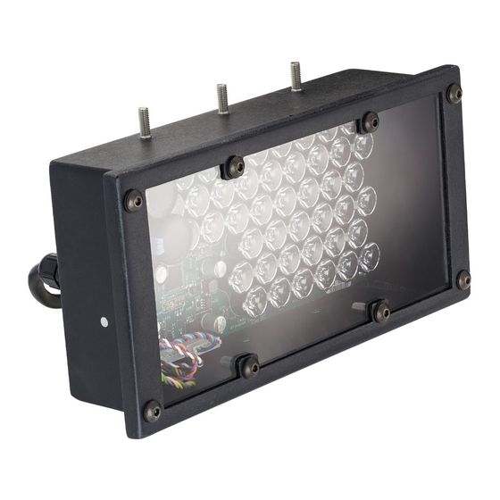
Getting started This user manual describes the setting up and operation of the VCT6 strobe light. The VCT6 is a strobe light suitable for use in traffic applications. It is available in white or infrared and can be controlled through an Ethernet connection or RS232 depending on the version specified. -
Page 6: Safety
Safety Read this before using the VCT6. Always observe the following safety precautions. If in doubt, contact your distributor or Raytec. The following symbols mean: Warning: Read instructions to understand possible hazard. Warning: Surface may get hot. Warning: Possible hazardous voltage. -
Page 7: General
Installation guidance (disclaimer) This information is for guidance only. Installers must perform their own risk assessment specific to each installation. While Raytec has taken every care in the preparation of this advice, Raytec accepts no liability for damages of any kind except those required by law. -
Page 8: Iec/Bs En62471 Risk Groups
IEC/BS EN62471 Risk Groups 2.5.1 The following applies to all variants of the VCT6 running full power and at maximum duty cycle: Risk Group 2 — VCT6-850-14-xxx — VCT6-850-28-xxx — VCT6-850-50-xxx — VCT6-940-14-xxx — VCT6-940-28-xxx — VCT6-940-50-xxx Exempt — VCT6-W-12-xxx —... -
Page 9: Sicherheit
Sicherheit Bitte lesen Sie vor Verwendung des VCT6 diese Informationen. Beachten Sie immer die folgenden Sicherheitshinweise. Wenden Sie sich im Zweifelsfall an Ihren Händler oder Raytec. Die folgenden Symbole haben die folgende Bedeutung: Warnung: Lesen Sie die Hinweise, um eine mögliche Gefahr zu verstehen. -
Page 10: Allgemein
Risikobewertung für die jeweilige Installation durchführen. Auch wenn Raytec diese Empfehlung mit größter Sorgfalt erstellt hat, übernimmt Raytec keine Haftung für Schäden jeglicher Art, außer in dem gesetzlich erforderlichen Maße. Vorsätzliche Gefährdungs- oder Zerstörungshandlungen werden in diesem Dokument nicht behandelt und... -
Page 11: Sicherheitsleitfaden Für Augen/Haut
Sicherheitsleitfaden für Augen/Haut Hohe künstliche optische Strahlung kann sowohl Augen als auch Haut schädigen. Für eine derartige Gefährdung wurden Expositionsgrenzwerte festgelegt. Alle Lichtsysteme werden in Risikogruppen eingeteilt, die das Risikoausmaß bei normaler Verwendung der Leuchte definieren. Bei der Verwendung müssen die dieser Risikogruppe entsprechenden Vorsichtsmaßnahmen getroffen werden und dafür gesorgt werden, dass im Nahbereich der Leuchte niemand Schaden nehmen kann. -
Page 12: Sécurité
Lisez ce document avant d'utiliser le VCT6. Respectez les mesures de sécurité suivantes en toutes circonstances. En cas de doute, contactez votre distributeur ou Raytec. Les symboles ci-dessous auront la signification suivante: Attention: Lisez les instructions pour comprendre quels sont les risques éventuels. -
Page 13: Généralités
Ces informations sont seulement à titre indicatif. Les installateurs doivent effectuer leur propre évaluation des risques, pour chaque installation. Même si Raytec a préparé minutieusement ces conseils, Raytec décline toute responsabilité pour tout dommage, quel qu'il soit, à l'exception de ceux requis par la loi. -
Page 14: Conseils De Sécurité Pour Les Yeux Et La Peau
Conseils de sécurité pour les yeux et la peau Des niveaux élevés de rayonnements optiques artificiels peuvent causer des dommages aux yeux et à la peau. Les valeurs limites d’exposition ont été établies pour de tels dangers. Tous les systèmes d’éclairage sont placés dans des groupes de risque, qui définissent le niveau de risque lorsque l’éclairage est utilisé... -
Page 15: Mounting The Vct6
Mounting the VCT6 Half nuts are fitted permanently to the six M5 mounting studs on the standard VCT6. If these studs are fitted to your unit, do not attempt to remove them. -
Page 16: Heat-Sinking
Heat-sinking The heat dissipation of the VCT6 can be calculated as follows: HD = (6 x Br x PW x TF) + 2 Where: HD = Heat dissipation in Watts PW = Strobe pulse width in seconds TF = Maximum trigger frequency in Hertz Br = Brightness of light output in percent. -
Page 17: Connecting The Vct6
Connecting the VCT6 All connections to a standard VCT6 are made through an unterminated, screened 12 core cable. The length of this cable is typically 2000mm ± 100mm. The terminations for this cable are explained in Section 6.1, Ethernet variants and Section 6.2, RS232 variants. - Page 18 Wire colour Function (RS232) Brown Trigger in + Grey Not connected Pink Yellow Green Orange Trigger out – Violet Trigger out + Screen Case ground Note: Using a 9-way D-type connector, the following connections are made: Wire colour Pink Yellow Green For RS232 units fitted with a cable assembly terminated with Mini-Fit connectors, refer to the table overleaf:...
-
Page 19: Connecting The Power Supply
Wire colour Function Connector Connector Terminal Black Power supply - 8 Way Molex part no. Blue Power supply - 39-01-3083 Power supply+ Fitted with crimp Turquoise Power supply+ contacts: 39-00-0040 White Trigger in - Brown Trigger in + Orange Trigger out - Violet Trigger out + Yellow... -
Page 20: Trigger Input
Trigger input The trigger input is opto-isolated. The opto-isolator isolates voltages up to 50V. Signal Function TRIGI – Trigger input – TRIGI + Trigger input + The trigger input circuit is shown below: The trigger input circuit operates as follows: Logic 1 (on) When a voltage of 5V to 24V is applied across TRGI negative (-) and TRGI positive (+), the trigger input is logic 1 (on). -
Page 21: Trigger Output
Trigger output The trigger output is opto-isolated and can be used to trigger other external equipment, such as additional lights or an external camera. The opto-isolator isolated voltages up to 50V. The outgoing pulse length and transmission delay can be adjusted, enabling the complete control of the trigger timing between a VCT6 and a camera. -
Page 22: Communications
Communications The VCT6 may be specified as having Ethernet or RS232 communications. 6.6.1 Ethernet option The Ethernet connection is 10-Base T and runs at 10Mbits per second. Serial option 6.6.2 The RS232 connections are as follows: The communications port should be set to 115200 baud, no parity, 8 data bits and 1 stop bit. -
Page 23: General Description
General description Two modes of operation are provided for the light output: Pulse (strobe) — the output is pulsed once per trigger. One trigger input is used as a trigger. The delay from trigger to pulse, the pulse duration and the brightness can all be set. -
Page 24: Pulsed Output
Pulsed output The output is off by default. When the VCT6 is triggered, it waits for a delay and then pulses the output. Re-trigger delay is the minimum allowed time from one trigger to the next. Any triggers that occur too soon after the previous trigger are ignored. The re-trigger delay is set in multiples of 100μs. -
Page 25: Trigger Input Options
Trigger input options The trigger sense and the way the VCT6 is triggered can be changed according to how you set the 'P' flag. This is summarised in the table below: Mode Trigger input Output Is off if P Flag = 1 Input = off Is on if P-Flag = 0 Switched... -
Page 26: Ethernet Address
Ethernet address When setting up Ethernet versions of the VCT6, you may need to ask your network administrator for advice about making the Ethernet connection. Ethernet set-up is not affected by power cycling the VCT6. The Ethernet link uses a 10-base T connection. An RJ45 connector may be wired to the free end of the cable to facilitate this. -
Page 27: Programmed Ip Address And Dhcp
RaytecMaint allows you to view the controllers on your network, change their IP addresses and upgrade their firmware if it becomes necessary. In the messaging section of RaytecMaint, you can communicate with your light using the commands explained in Section 10, Configuration commands. You can also open the light's web pages by clicking the Link to controller webpage button. -
Page 28: Fixed Ip Address
Fixed IP address 8.2.2 When using a fixed IP address, you must ensure that you use an IP address that is not being used by any other device on the network. It is usual to keep the first three numbers of the IP address (which are comprised of the first seven digits, in the example below) the same as those of other devices on your network and to change only the last number (the digits after the last point). -
Page 29: Webpage Configuration
Webpage configuration You can set up the VCT through its own internal web page. Click the Open webpage button in RaytecMaint to take you directly to the VCT6’s web pages. You can also type the light’s IP address (displayed in RaytecMaint) into your web browser, which will display the main page. -
Page 30: General Setup Page
General setup page On the General setup page, you can set up a password for the VCT6 and send it commands. Refer to Section 10, Configuration commands for the commands you can use to operate the VCT6. You can also set up the trigger mode and turn the internal trigger on or off. -
Page 31: Light Configuration Page
Light configuration page The Light configuration page (shown below) allows you to set up the light's parameters. You can set the mode (continuous, pulsed, or switched), the light's brightness and pulse settings. You must click the Submit button to effect any changes you make. -
Page 32: Trigger Output Configuration Page
Trigger output configuration page The internal trigger configuration page (shown below) allows you to set up the pulse parameters for the trigger output pulse. -
Page 33: Configuration Commands
Configuration commands The VCT6 can be configured through the Ethernet connection using UDP or TCP/IP. A configuration program with source code can be downloaded from www.gardasoft.com. Ethernet communication For TCP, commands from a host should be sent to destination port 30313. Replies are sent to destination port 30312. -
Page 34: General Commands
For example: Parameter Meaning 0.1 milliseconds 200us 200 microseconds 0.1s 0.1 seconds Note: The characters are in USA/UK format, so that ‘a half’ is written as ‘0.5’ (rather than ‘0,5’). The command codes and their meanings are summarised below (that is, in the table on the next page). - Page 35 Report the configuration ST This command reports all the channel settings. A typical output is: CH 1, MD 1, S 100.0 DL 10us, PU 1.000ms, RT 1.020ms, IP1,FL0, CS0.000A, RA24V CH 2, MD 1, S 100.0 DL 10us, PU 1.000ms, RT 1.020ms, IP1,FL0, CS0.000A, RA36V Where: Channel number...
- Page 36 Enable Ethernet messages Where: = 0 to disable Ethernet messages = 1 to enable Ethernet messages When Ethernet messages are enabled, any error reports are sent to the most recent UDP or TCP addresses from which a command has been received.
-
Page 37: Lighting Commands
Lighting commands 10.3 The lighting command codes, and their meanings are described below. The upper-case commands are shown, followed by lower case letters denoting the numeric argument. Note that any changes using these commands are not saved permanently until the AW command has been issued. Set switched mode The output is set to switched mode at a specified percentage of full brightness. - Page 38 P Flag: 0 is set (positive triggers), 4 is cleared (negative triggers). Set the internal trigger This command enables or disables the internal trigger. When enabled, all outputs are triggered simultaneously using an internal trigger signal. This setting can be saved to non-volatile memory using the AW command.
-
Page 39: Command Summary
Command summary 10.4 Command Example Effect Save changes. Clear configuration. Show configuration. Enable Ethernet messages. Clear any error condition. EY65,66 Set web page password to 'AB' (where 'A' is ASCII character 65, and 'B' is 66, and so on). See note below. -
Page 40: Reference Information
Reference information This section gives the electrical ratings and details of any restrictions on the use of your VCT6. Event and error codes are also listed. Ratings and restrictions 11.1 The electrical ratings for the connections are as follows: Signal Rating Power input: The VCT6 operates 11.0V DC minimum to 26.4V DC... -
Page 41: Error Codes
Error codes 11.3 Error No Reason Err 1 A parameter value is invalid. Err 2 Command not recognised. Err 3 A numeric value is in the wrong format. Err 4 There is an incorrect number of parameters. Err 5 This is a warning and not an error. One of the parameters is out of range.
Need help?
Do you have a question about the PULSESTAR VCT6 Series and is the answer not in the manual?
Questions and answers