
Related Manuals for Senztek SolaStat-ST


Summary of Contents for Senztek SolaStat-ST
- Page 1 SolaStat An Intelligent Technology Solution for Water Heating INSTALLATION GuIde FOR QUALIFIED PERSONNEL ONLY...
- Page 2 ...
-
Page 3: Table Of Contents
Sensor Maintenance ..................32 Trouble Shooting Guide ................. 34 Programming Table ..................36 Specifications ....................37 For technical help contact your distributor. Distributor Details: www.senztek.com Senztek Holdings Ltd. 2009 Version 1.4 – March 2009 Table of Contents... -
Page 4: Before You Begin Installation
SolaStat™- ST Installation Guide EFORE EGIN NSTALLATION Assemble the The SolaStat™ Controller is supplied with the following components: components Roof sensor you will need Tank sensor Inlet sensor Mains Cable Pump Cable Associated screws ... - Page 5 SolaStat™- ST Installation Guide EFORE EGIN NSTALLATION ONTINUED Assemble the You will need the following tools to install the SolaStat™: tools you will Philips1 screwdriver for lid screws need Pozi 2 screwdriver for mounting screws Note: These tools are needed to mount the SolaStat™ only, and other tools may be needed for the remainder of the installation including the sensors.
- Page 6 SolaStat™- ST Installation Guide EFORE EGIN NSTALLATION ONTINUED Installers need to ensure the following: Installation Precautions: The Controller must be installed away from water sources such as rain, leaking pipes, or wet floors and must not be installed in damp areas like bathrooms.
- Page 7 SolaStat™- ST Installation Guide EFORE EGIN NSTALLATION ONTINUED Electrical When undertaking electrical installations, please note the following Precautions: All mains voltage electrical work must be carried out by a qualified electrician, especially external power outlet socket installation. A readily accessible disconnect device, overcurrent device and RCD Protection rated to suit the size of the pump plus 5VA must be incorporated in the power supply wiring.
-
Page 8: Installing The Solastat™ Controller
SolaStat™- ST Installation Guide ™ C NSTALLING THE ONTROLLER Overview The diagram below shows how the SolaStat™ is connected to the Hot Water Cylinder (HWC), the collector, and the three sensors (ROOF, TANK and INLET). Continued on next page Version 1.4 – March 2009 Page 5... - Page 9 SolaStat™- ST Installation Guide ™ C NSTALLING THE ONTROLLER ONTINUED Where to The SolaStat should be mounted so that: mount the 1. It is against a flat surface with sufficient strength to hold the enclosure SolaStat and any additional weight from the plugs, sockets and cables, 2.
-
Page 10: Mounting The Sensors And Connecting Wiring
SolaStat™- ST Installation Guide OUNTING THE ENSORS AND ONNECTING IRING Introduction The locations and way that the sensors are mounted is critical to ensure the SolaStat™ - operates correctly and at greatest efficiency; protects the system against damage from extreme temperatures, and ... - Page 11 SolaStat™- ST Installation Guide OUNTING THE ENSORS AND ONNECTING IRING ONTINUED Positioning The INLET Sensor should be fitted into a metal immersion ‘pocket’ above the HWC electric element near the bottom of the tank (usually just above the the Inlet Sensor element).
- Page 12 SolaStat™- ST Installation Guide OUNTING THE ENSORS AND ONNECTING IRING ONTINUED Connect the The SolaStat™ is normally supplied pre-wired, hence wiring inside the controller should not be necessary. Wiring However, if needed, the wiring diagrams below show you how to wire the unit for single and dual elements.
-
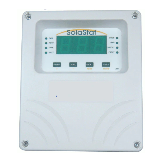
Page 13: Powering Up
SolaStat™- ST Installation Guide OWERING Before you Before you power up, make sure you have Connect the Read the safety instructions, warnings and liability statements, Power Completed installation, and Securely mounted the unit in place before you connect power to the unit. ... - Page 14 SolaStat™- ST Installation Guide OWERING ONTINUED What you will When you power up the unit, it will look like the picture below. Check that the PUMP is operating by pressing the PUMP button. This will turn the pump on for as long as you hold it down, unless it is already operating A digital readout of the TANK temperature.
- Page 15 SolaStat™- ST Installation Guide OWERING ONTINUED Note When the SolaStat is turned on for the first time, BioSafe will be turned on for an hour, if both TANK and INLET temperatures are higher than BioSafe Temperature. The unit will continue to monitor the hot water tank. If the TANK or INLET temperature is below the BioSafe temperature for about 72 hours, BioSafe will be activated again.
-
Page 16: Plumbing Tips
SolaStat™- ST Installation Guide LUMBING Overview This section will help you to ensure the plumbing associated with the SolaStat™ will enable the system to be operated safety and to maximum efficiency. All plumbing installations should be carried out by registered and qualified plumber;... - Page 17 SolaStat™- ST Installation Guide LUMBING ONTINUED Pressure Solar hot water systems can run much hotter than standard domestic hot water systems. Hotter water expands more, and needs high quality pressure Relief Valves relief valves to ensure the tank or other components do not burst under pressure.
- Page 18 SolaStat™- ST Installation Guide LUMBING ONTINUED Pump To prevent cavitation: Cavitation Make sure the pump is appropriate for the installation On a variable speed pump, make sure the setting is correct – a slower speed that still has enough head pressure is best, as it will minimise the pressure difference at the pump.
-
Page 19: About The Pump Settings
SolaStat™- ST Installation Guide BOUT THE ETTINGS Introduction The SolaStat™ works by turning the pump when the difference between the temperature at the solar hot water Collector (ROOF) and the INLET is at a certain level. The pump turns on when the difference between these two temperatures is high (i.e. - Page 20 SolaStat™- ST Installation Guide BOUT THE ETTINGS ONTINUED Adjusting the If you increase the PUMP ON value, the solar heater will heat up more Setting before the heat is transferred to your hot water tank. Hotter water will enter your tank, but it may take longer to heat the water to that level;...
-
Page 21: Holdoff, Reheat And Biosafe Functions
SolaStat™- ST Installation Guide OLDOFF EHEAT AND UNCTIONS Introduction The Holdoff, and Reheat functions operate together to ensure that heating the tank and pump operation are properly coordinated to maximise energy efficiency. They work together with the BioSafe function, which ensures that the temperature in your tank is raised to a pre-determined value at least once every 72 hours. - Page 22 SolaStat™- ST Installation Guide OLDOFF EHEAT AND UNCTIONS ONTINUED Holdoff, This example shows how Holdoff, Reheat and BioSafe modes can all work together: If the settings are: Reheat and BioSafe Mode Holdoff Timer = 4 hours Reheat Lower = 40ºC / 104ºF ...
- Page 23 SolaStat™- ST Installation Guide OLDOFF EHEAT AND UNCTIONS ONTINUED Reheat and This example shows how reheat and BioSafe can work together. If the settings are: BioSafe Mode. Holdoff Timer = ‘OFF’ Reheat Lower = 40ºC / 104ºF Reheat Upper = 55ºC / 131ºF ...
-
Page 24: Programming The Solastat
SolaStat™- ST Installation Guide ™ ROGRAMMING THE The SolaStat™ settings have been factory set with the pre-set values specified in the Programming Table at the end of this manual. These settings should not require any changes. Caution: incorrect settings of these values could damage the solar collector and/ or the pump. - Page 25 SolaStat™- ST Installation Guide ™, ROGRAMMING THE ONTINUED When you have entered the Installer programming mode, the PUMP light will Enter Adjustable be flashing. The unit is now ready to accept the ‘Maximum’ Value entry, and Values subsequent values. After each key press, you have one minute to press another key before the unit times out.
- Page 26 SolaStat™- ST Installation Guide ™, ROGRAMMING THE ONTINUED Adjust the The PUMP OFF Temperature determines the temperature at which the pump will be turned off, to allow the water in the cylinder to heat up fully (i.e. make PUMP OFF Temperature sure that the warmer water in the cylinder is not diluted with colder water).
- Page 27 SolaStat™- ST Installation Guide ™, ROGRAMMING THE ONTINUED Adjust the The PUMP ON temperature determines the temperature of the tank that will activate the pump, to transfer water into the hot water cylinder. PUMP ON Temperature The Standard Value is 12°C / 53.6°F, and the range is 2°C – 21°C / 36°F – 70°F. It is always set to a higher level than the PUMP Off temperature.
- Page 28 SolaStat™- ST Installation Guide ™, ROGRAMMING THE ONTINUED Adjusting the The Holdoff Timer controls how long after the last Pump operation elapses until the electric element can be switched on – unless the temperature fall Holdoff Timer below the Reheat Lower temperature (see next page). This stops the Hot Water Cylinder element from coming on when solar heated water is being pumped into the tank during the day.
- Page 29 SolaStat™- ST Installation Guide ™, ROGRAMMING THE ONTINUED The Reheat Lower function makes sure that the user will not run out of hot Reheat Lower Value water. It sets the temperature (in the tank) at which the heating element will automatically start to reheat the water in your cylinder.
- Page 30 SolaStat™- ST Installation Guide ™, ROGRAMMING THE ONTINUED The Reheat Upper value sets the temperature (in the tank) at which the Reheat Upper Value heating element will automatically stop reheating the water in your cylinder, after the Reheat Lower has turned it on. The Reheat Upper acts as a thermostat for the tank (provided the Holdoff Timer and BioSafe are not active).
- Page 31 SolaStat™- ST Installation Guide ™, ROGRAMMING THE ONTINUED The BioSafe function makes sure that tepid water in your cylinder does not BioSafe Settings cause is set at a temperature that does not allow biological contamination to occur. It does this by ensuring the water in your tank reaches 60°C at least once every 72 hours –...
- Page 32 SolaStat™- ST Installation Guide ™, ROGRAMMING THE ONTINUED Set the The Topout temperature is the maximum temperature that you will allow in the cylinder. Very high temperatures in the cylinder can cause damage Topout Temperature (especially for ceramic lined tanks) – both from heat, and from high pressures on plumbing fittings.
- Page 33 SolaStat™- ST Installation Guide ™, ROGRAMMING THE ONTINUED Adjust the The Frost value is installed in some (but not all) units. FROST Value It is designed to protect your collector and hot water system from freezing and bursting. When this temperature is reached, the pump will come on just enough to raise the temperature of water by 2 - 3°C/ 4 –...
- Page 34 SolaStat™- ST Installation Guide ™, ROGRAMMING THE ONTINUED Selecting You can select whether temperatures are given in Celsius or Fahrenheit using the next programmable value. Celsius or Fahrenheit Use the + or – button to toggle the setting between Celsius and Fahrenheit. Press STORE to save all values and exit programming mode to automatic operation.
-
Page 35: Sensor Maintenance
SolaStat™- ST Installation Guide ENSOR AINTENANCE Lengthening The sensor wire can be lengthened within certain guidelines: Sensor Wire The absolute maximum cable length is 100m (328 feet). Over 20m (66 feet), care must be taken to avoid electrical interference being picked up. - Page 36 Tighten the screws on the cable clamp. 9. Replace the lid, replace the four screws and tighten. 10. Push in four new screw covers available from your distributor or Senztek. Note: there are locating lugs to ensure correct orientation. 11. Reconnect the SolaStat and turn on the power.
-
Page 37: Trouble Shooting Guide
SolaStat™- ST Installation Guide ROUBLE HOOTING UIDE Symptom Cause Solution No operation, no No power/fault Check mains outlet. display and no lights Check fuses. (No Power Light) POWER light ON but Power brown out (mains power not Switch off power while mains no display or running at full voltage) - Page 38 SolaStat™- ST Installation Guide Symptom Cause Solution HWC Light flashing HWC BioSafe value has not been Wait for the tank to heat up to fast (3 times each reached Biosafe temperature second) Tank Thermostat incorrectly set Check tank Thermostat is set below BioSafe ...
-
Page 39: Programming Table
SolaStat™- ST Installation Guide ROGRAMMING ABLE Your installer may enter special programming information for your controller in the table below. Settings can be changed by a certified installer or maintenance technician. Adjustable Function Light Pre-Set Value Range Values indication The temperature difference Flash Pump 1-20 °C... -
Page 40: Specifications
SolaStat™- ST Installation Guide PECIFICATIONS Power Supply. Supply Voltage 85 – 264 Vac (high) OR 22 – 85 Vdc (medium) (must be specified at time of ordering) Max power usage 5VA + external loads. Relay Outputs. Pump: 10A (240Vac) Resistive for pre-wired option 16 A (240 Vac) Resistive for permanent wired option 1HP (240Vac) Inductive (motor) HWC: 10A (240Vac) Resistive for pre-wired option... - Page 41 ...
- Page 42 ...
- Page 43 ...
- Page 44 Senztek NZ Ltd Senztek Australia Ltd Senztek UK Ltd...
Need help?
Do you have a question about the SolaStat-ST and is the answer not in the manual?
Questions and answers