Advertisement
Advertisement

Related Manuals for Toptech TT-RE250D

Summary of Contents for Toptech TT-RE250D
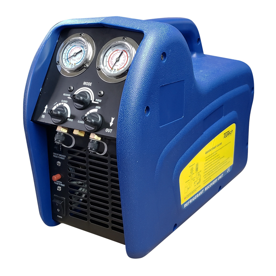
- Page 1 USER MANUAL REFRIGERANT RECOVERY UNIT...
-
Page 2: Table Of Contents
TABLE OF CONTENTS G E N E R A L S A F E T Y G U I D E L I N E S … … … … … … … … … … … … … … 2 S P E C I F I C A T I O N S …... -
Page 3: General Safety Guidelines
GENERAL SAFETY GUIDELINES 1. Read all safety, operating guidelines and instructions before operating this recovery machine. 2. Always think before acting, familiarity breeds carelessness, and carelessness can be harmful to your health, or worse, result in death. 3. Only a qualified technician should operate this Recovery machine. 4. - Page 4 GENERAL SAFETY GUIDELINES 14. A dry filter must always be used and should replace frequently. And each type of refrigerant must have its own filter. For the sake of assuring the normal operation of the unit, please use the filter specified by our company. High quality dry filters will bring high quality services.
-
Page 5: Specifications
SPECIFICATIONS MODELS TT-RE250D CAT.III:R-12, R-134A, R-401C, R-406A, R-500 CAT.IV:R-22,R-401A, R-401B,R-402B,R-407C,R-407D, REFRIGERANTS R-408A,R-409A,R-411A,R-411B,R-412A,R-502, R-509 CAT.V:R-402A,R-404A,R-407A,R-407B,R-410A,R-507 VOLTAGE 110/230VAC 50/60HZ COMPRESSOR 1/2HP OIL-LESS MAX CURRENT 4A@50HZ 8A@60HZ HP SHUT-OFF 38BAR/550PSI CAT.III CAT.IV CAT.V VAPOR 0.23KG/MIN 0.25KG/MIN 0.26KG/MIN RECOVERY RATE LIQUID 1.57KG/MIN 1.81KG/MIN 1.85KG/MIN PUSH/PULL 4.64KG/MIN... -
Page 6: Standard Liquid/Vapor Recovery Procedure
STANDARD LIQUID/VAPOR RECOVERY PROCEDURE Make sure this recovery machine is in good operating condition. 2. Make sure all connections are correct and tight. 3. Open the liquid port of the storage tank. 4. Make sure the MODE valve is set on RECOVERY. 5. - Page 7 7. Connect the recovery machine to a right outlet. (See the nameplate on the machine) Switch the power switch to the ON position, you should hear the fan running, then press the START switch to start the compressor. 8. Slowly open the input port on the machine. 1) If the compressor starts to knock, slowly throttle back the input valve until the knocking stops.
- Page 8 SELF-PURGING PROCEDURE Procedure for purging remaining refrigerant from this machine. 1. Close the ports of the system being serviced that are connected to the input/out of the machine. 2. Turn off the recovery machine. 3. Turn the Input valve to the PURGE position. 4.
-
Page 9: Liquid Push/Pull Procedure
LIQUID PUSH/PULL PROCEDURE Push/pull procedure only works with large systems where the liquid refrigerant is no less than 6.8kg (151bs.). 1. Put MODE valve knob on RECOVERY. 2. Open OUTPUT valve. 3. Open INPUT valve. 4. When the scale stops rising close all ports. 5. - Page 10 LIQUID PUSH/PULL PROCEDURE In order for this procedure, you must have a minimum of 5 lbs. (2.3kg) of liquid refrigerant in the storage tank. 1. Connect the hoses as shown. 2. Turn the MODE valve to the Recovery position. 3. Open the Vapor and Liquid valve of the storage tank. 4.
-
Page 11: Ta N K C O O L I N G P R O C E D U R E ( O P T I O N A
TANK COOLING PROCEDURE (OPTIONAL) Set up your equipment as shown, it is possible to cool the storage tank during the recovery procedure if necessary. 1. Open the vapor valve of the storage tank (it is closed while recovering). 2. Close the two valves of the manifold gauge set. 3. - Page 12 TROUBLESHOOTING PROBLEM CAUSE ACTION Power supply cord not Attach the power supply cord. Fan does not run when Power attached voltage is not right Check the power supply at job site. Switch is in ON position The circuit breaker has cut off Press the button to reset The recovery machine is in Reduce pressure and then press the...
-
Page 13: W I R I N G D I A G R A
WIRING DIAGRAM WIRING DIAGRAM-STANDARD... -
Page 14: Part S D I A G R A
WIRING DIAGRAM -LOW PRESSURE SHUT OFF FUNCTION PARTS DIAGRAM FOR TT-RE250D SERIES 1. PLASTIC CASE 9.POWER SWITCH 17.TRAP/TUB 2. CONTROL VALVE 10.DRYER/FILTER 18.BASE 3. FRONT PANEL 11.HOSE 19.RUBBER FOOT 4. INPUT GAUGE 12.TRAP/TUB 20.CONDENSER 5. OUTPUT 13.TRAP/TUB 21.FAN 6. KNOB 14.COMPRESSOR...
Need help?
Do you have a question about the TT-RE250D and is the answer not in the manual?
Questions and answers