Table of Contents

Related Manuals for Gas Sense GS-220.P

Summary of Contents for Gas Sense GS-220.P
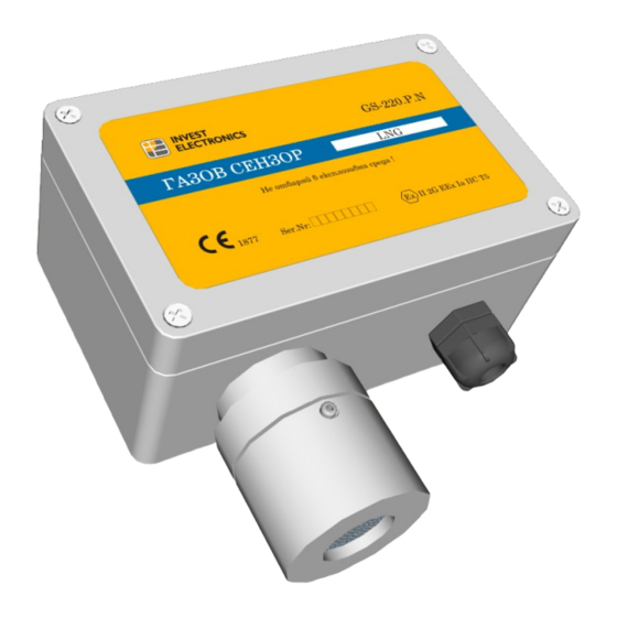
- Page 1 Invest Electronics LTD GS-220.P GAS SENSOR mount • settings • operation • maintenance mount and exploitation manual (version 1.0/October 2007) Invest Electronics reserve the right for changes in the document without notification...
-
Page 2: Table Of Contents
Gas Sensor GS-220.P www.gassense.eu GS-220.P CONTENTS 1. Introduction ....................4 1.1. Safety instructions .................. 4 1.2. Specifications ..................5 1.3. Certificates and standards ..............5 2. Product review ..................... 6 2.1. General review ..................6 2.2. Typical application .................. 7 2.3. - Page 3 Gas Sensor GS-220.P www.gassense.eu 7. Customer support ..................20 7.1. Contact information ................20 7.2. Warranty ....................20 7.3. Order codification ................. 21 APPENDIX A – abbreviations ................ 22 APPENDIX B – order codes ................23 ver.1.0 page 3 / 23...
-
Page 4: Introduction
Gas Sensor GS-220.P www.gassense.eu CHAPTER INTRODUCTION 1.1. Safety instructions Before using the unit read carefully the manual. It consists important information, regarding user safety and correct system exploitation. Gas sensor must be mounted only by licensed personnel ! Electrical installation: Electrical connections must be done only by licensed electrical installer. -
Page 5: Specifications
Gas Sensor GS-220.P www.gassense.eu 1.2. Specifications Parameters Value Dimensions 125х125х58mm Electrical supply 12 ÷ 24 VDC Power consumption max 2W Controlled gases Combustible and toxic (for full list ref. to APPENDIX B) Signalization levels Sensor element Semiconductor, catalytic or electrochemical... -
Page 6: Product Review
Gas Sensor GS-220.P www.gassense.eu CHAPTER PRODUCT REVIEW 2.1. General Review GS-220 gas sensor is designed to detect and control combustible and toxic gases in the atmosphere. They are compatible with GA-220 series gas controllers and with other devices with digital outputs. Its main specification are: Detection and control for over 20 types of gases ✔... -
Page 7: Typical Application
Gas Sensor GS-220.P www.gassense.eu 2.2. Typical application Gas sensor GS-220 is offered in different variations, depending on gas sensor element. It gives solutions for control of over 20 types of gases. Few of its typical applications are: underground parking garages ✔... -
Page 8: Mount
Gas Sensor GS-220.P www.gassense.eu CHAPTER MOUNT 3.1. Introduction Warning: gas controller must be mounted only by licensed technician, familiar with this document or authorized by the manufacturer. GS-220 is designed for mount via 2 bolts situated cornerwise on the panel. It’s connected to the gas controller by four core cable. -
Page 9: Dimensions
Gas Sensor GS-220.P www.gassense.eu 3.4. Dimensions Gas sensor GS-220 is produced in aluminum corpus with ingress protection IP65. Dimensions and installation openings on the corpus are shown on figure 3.1. Note: all dimensions are in millimeters- mm Figure 3.1. – Dimensions and mounting holes. Front view ver.1.0... -
Page 10: Mechanical Installation
Gas Sensor GS-220.P www.gassense.eu Figure 3.2 – Dimensions. Side view 3.5. Mechanical installation Gas sensor GS-220 is attached via 2 bolts φ3,8 х 35. When attaching to wall keep the following steps for gas sensor attachment : 1. Drill openings into the wall according to fig. 3.1. - Page 11 Gas Sensor GS-220.P www.gassense.eu Figure 3.3 – Take off sensor’s lid 5. Screw bolts (2 bolts) into the dubels on the wall Figure 3.4 – wall mounting 6. Proceed to electrical mount. ver.1.0 page 11 / 23...
-
Page 12: Electrical Installation
Gas Sensor GS-220.P www.gassense.eu 3.6. Electrical installation Gas sensor GS-220 is connected to the gas controller or other executing device via three or four core cable. The recommended connecting conductor’s sections according to line length are shown in table 3.1. - Page 13 Gas Sensor GS-220.P www.gassense.eu 4. Connect corresponding terminals of gas controller and gas sensor: + ↔ + 1 ↔ 1 ; 2 ↔ 2 ; - ↔ - ; Figure. 3.6. – connecting cable to terminal 5. Close the panel and screw four bolts 6.
-
Page 14: Settings
Gas Sensor GS-220.P www.gassense.eu CHAPTER SETTINGS 4.1. Introduction This chapter describes sensor adjustments. Testing and calibration of sensors must be done at least once every 6 months. 4.2. Calibration Tools necessary for GS-220 gas sensor calibration test gas for danger level ✔... - Page 15 Gas Sensor GS-220.P www.gassense.eu Steps for setting up GS-220 gas sensor 1) For sensors with semi conductor gas sensing element (ref. APPENDIX B) the device needs to be previously warmed up for at least one hour. 2) Switch on voltmeter between outputs GND and SENSE (1 and 4 ) of...
-
Page 16: Operation
Gas Sensor GS-220.P www.gassense.eu CHAPTER OPERATION 5.1. Operating modes This chapter shows operating modes of gas sensor GS-220, their activation, as well as indications and output signals, which are generated in each one. 5.1.1. Warm up mode This is the mode that starts right after the powering of the sensor. It is used for stabilizing measurements of the diagram as well as initial warming of the gas sensitive element (gas sensitive element must be warm in order to measure right). -
Page 17: Danger Mode
Gas Sensor GS-220.P www.gassense.eu Characteristics Values LED indication DANGER – does not light • ALARM – does not light • FAULT – does not light • Digital outputs DANGER ( terminal ) – digital „0“ • ALARM ( terminal ) – digital „0“... - Page 18 Gas Sensor GS-220.P www.gassense.eu Characteristics and output levels of fault mode: Characteristics Values LED indication DANGER – does not light • ALARM – does not light • FAULT – lights • Digital outputs DANGER ( terminal ) – digital „0“...
-
Page 19: Maintenance
Gas Sensor GS-220.P www.gassense.eu CHAPTER MAINTENANCE 6.1. Check and re-adjustment Technically gas sensitive elements used in GS-220 sensor, have specific life time period. And their gas sensitivity towards the gas decreases with time. Preventive maintenance and/or re-adjustment at least once every six months must be held. - Page 20 Gas Sensor GS-220.P www.gassense.eu CHAPTER CUSTUMER SUPPORT 7.1. Contact information INVEST ELECTRONICS LTD. 145 Brezovsko shose street Plovdiv 4003 Bulgaria Tel. + 359-32-960143 Fax: + 359-32-960144 e-mail: info@investelectronics.com web: http://www.gassense.eu 7.2. Warranty Warranty period is 12 months, but not more than 18 months from date of ✔...
- Page 21 Gas Sensor GS-220.P www.gassense.eu The warranty does not cover: batteries, adapters and other consumables. This warranty does not apply to cosmetic damages on the outside of the corpus, as well as normally wear of mechanical and electrochemical components, due to normal operation.
- Page 22 Gas Sensor GS-220.P www.gassense.eu APPENDIX А ABBREVIATIONS Abbreviation Meaning А Ampere Alternating Current Accumulator Atmospheres Explosibles – European directive for devices operating in combustible ATEX environment Battery Bits per second Common / common relay output The product confirm with all European directives...
- Page 23 Gas Sensor GS-220.P www.gassense.eu APPENDIX ORDER CODIFICATION Chemical Measure Dimen- Code Sensor formula range sion GS-220.P.N.01-02 Methane semiconductor 0 ÷ 100 % LEL GS-220.P.N.01-07 Hydrogen semiconductor 0 ÷ 100 % LEL GS-220.P.N.01-13 Acetone semiconductor 0 ÷ 100 % LEL GS-220.P.N.01-14...
Need help?
Do you have a question about the GS-220.P and is the answer not in the manual?
Questions and answers