Table of Contents

Related Manuals for SMARTSCAN 7000 Series

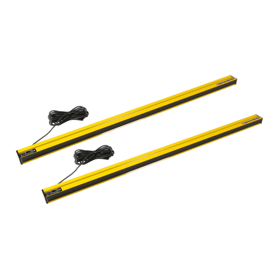
Summary of Contents for SMARTSCAN 7000 Series
- Page 1 SS-7K SEP02 7000 SERIES LIGHT CURTAINS HANDBOOK Smartscan Ltd, Pywell Road, CORBY, NN17 5XJ, UK Tel: +44 (0) 1536 401313, Fax: +44 (0) 1536 268954, Email sales@smartscan.com, www.smartscan.com ISSUE 1 7 0 0 0 S E R I E S...
- Page 2 7 0 0 0 S E R I E S...
-
Page 3: Table Of Contents
7000 SERIES LIGHT CURTAINS CONTENTS Page INTRODUCTION INTERFACE SPECIFICATION LIGHT CURTAINS 30mm DETECTION CAPABILITY LIGHT CURTAINS 70mm DETECTION CAPABILITY LIGHT CURTAINS FOR PERIMETER GUARDING INTERCONNECT CABLES CONTROL MODULE ACCESSORIES SAFETY SYSTEM SOLUTIONS INSTALLATION SHEET APPENDIX 1 APPENDIX 2 www.smartscan.com 7 0 0 0... - Page 4 7 0 0 0 S E R I E S...
-
Page 5: Introduction
INTRODUCTION 7000 Series Safety Light Curtains The 7000 Series offers a wide range of models for finger, hand, leg and body protection. The 7000 system from Smartscan is compact in size and provides many sophisticated control features as standard, including: 2 and 3 beam floating blanking for press and press brake applications, external test and auto or latched reset control options. - Page 6 Guillotines Production lines Robots 7000 Series light curtains comply with British and International Safety Standards for Light Curtains BS EN 61496-1 & BS IEC 61496-2 Type 4. They are normally used in situations which demand a high level of safety integrity, where the risk assessment for the safety related parts of a control system, as indicated in BS EN 954-1, determines a requirement up to and including Category 4 control equipment.
-
Page 7: Interface
OSSD switches. Green LED’s ON = OSSD1 and OSSD2 active ON Red LED’s ON = OSSD1 and OSSD2 inactive OFF Safety Relay Outputs (F2) - a number of 7000 Series control module types have on-board cross-monitored output switching relays. With these models the electronic outputs are connected via links to the inputs of the relay coils. - Page 8 INTERFACE Range (F6) - The range setting switch is mounted in the control module. The switch enables light curtain scanning ranges to be selected to suit a specific application. The dip switches can be set to provide the following ranges: 1) 0.5m to 1m 2) 1m to 4m 3) 4m to 15m. For settings refer to Fig.
- Page 9 The 7000 Series has the capability of 1, 2 and 3 beam floating blanking, offering much increased flexibility.
- Page 10 OFF. Safety relay input (F17) - Some 7000 Series control module types have on-board cross monitored output switching relays. With these models the electronic outputs are connected via links to the inputs of the relays.
-
Page 11: Specification
SPECIFICATION 7000 Series Light Curtains Number of beams 2 -112 Object detection 30mm, 70mm & Perimeter Guarding Detection zone 176mm to 2072mm (model dependent) Range 0.5 - 15m (model dependent) Light type Infra-Red 880nm Response time (relay output) 25ms Operating temperature 0°C to + 50°C... -
Page 12: Light Curtains 30Mm Detection Capability
LIGHT CURTAINS Light Curtains 30mm Detection Capability Range 15m Model Number Detection zone Weight number of beams (K) mm (Tx + Rx) Kg 072-150 072-151 072-152 072-153 072-154 072-155 072-156 1051 072-157 1196 072-158 1306 072-159 1488 072-160 1634 072-161 1780 072-162 1926... -
Page 13: Light Curtains 70Mm Detection Capability
LIGHT CURTAINS Light Curtains 70mm Detection Capability Range 15m Model Number Detection zone Weight number of beams (K) mm (Tx + Rx) Kg 072-201 072-203 072-204 072-205 072-206 1002 072-207 1235 072-208 1469 072-209 1818 7 0 0 0 S E R I E S... -
Page 14: Light Curtains For Perimeter Guarding
LIGHT CURTAINS Light Curtains Perimeter Guarding Range 15m Model Beam Overall length Weight number Pitch (M) mm (Tx + Rx) Kg 072-250 2 @ 500mm 072-251 3 @ 450mm 072-252 4 @ 400mm 1175 Interconnect Cables Model Length m number 071-303 071-306 7 0 0 0... -
Page 15: Control Module
CONTROL MODULES Control Module IP65 Mode Description number 072-103 Relay output (IP65) 072-107 Relay output with mute (IP65) Warning: Do not use inside control enclosures where temperature may exceed rating. amtri veritas Type Examined Report Number: 8/005027 Certificate Number: CK/KID/091/99 Certificate Number: AV EC 1456-A FM27829 7 0 0 0... - Page 16 7 0 0 0 S E R I E S...
-
Page 17: Accessories
(See appendix 2 for installation guidance). The Smartscan mirror system provides a sturdy floor mounting kit together with an aluminium column for mounting the mirror. The mirror assembly simply slots onto the column and can be adjusted to the height required for the application. - Page 18 ACCESSORIES Range of the Maximum range Maximum range light curtain through 1 mirror through 2 mirrors 0.5m – 15m Mirrors Model Description number 044-252 600mm x 110mm wide mirror unit 044-249 900mm x 110mm wide mirror unit 044-250 1200mm x 110mm wide mirror unit 044-253 1400mm x 110mm wide mirror unit Note: Mirror length must be a minimum of 100mm longer than the...
- Page 19 ACCESSORIES Power Supply If a suitable stabilised 24V DC, 2.5A power supply available the following unit is recommended. Model Description number 071-050 Power supply Input 85 - 264V AC Output 24V DC, 2.5A Features High reliability High efficiency, low working temp Built in EMI filter, low ripple noise Compact size, lightweight Short circuit, over load, over voltage protection...
- Page 20 ACCESSORIES Mounting Stands Designed to accommodate our range of safety light curtains. The Adjustable Stand (50mm x 50mm) offers the user a flexible mounting option. The stand has adjustable brackets that allow the safety light curtain to be mounted at different positions to suit a specific application.
- Page 21 ACCESSORIES Adjustable Mounting Stands Straight stands Model Description Height number 044 – 408 Pair of adjustable straight stands (with complete bracket set) 7 0 0 0 S E R I E S...
- Page 22 ACCESSORIES Channel Mounting Stands Straight stands Model Description Height number 044 - 118 Pair of channel floor stands (straight) 1.5m 044 – 218 Pair of channel floor stands (straight) 7 0 0 0 S E R I E S...
- Page 23 7 0 0 0 S E R I E S...
-
Page 24: Safety System Solutions
SAFETY SYSTEM SOLUTIONS Safety System Solutions Smartscan recognise the difficult balance that customers have to make between meeting Health & Safety legislation requirements and managing their demanding production needs. Smartscan design and manufacture systems to meet the particular needs of their customer’s safety applications - from single machines to full production lines. - Page 25 7 0 0 0 S E R I E S...
-
Page 26: Installation Sheet
Warning: Control modules and Transmitters / Receivers with serial numbers ending in X or T are not interchangeable with previous models. Mixing them may damage the units. Warning: You must Switch-off or disconnect the 7000 Series light curtain from the 24V power supply before connecting or disconnecting... - Page 27 INSTALLATION SHEET Control module – Protection rating IP65 – Din rail mounting or screw fix, 2 x M6 bolts. Suitable for mounting outside of a control cabinet. 072-103 – Relay output switching 072-107 – Relay output switching with mute function 7 0 0 0 S E R I E S...
- Page 28 INSTALLATION SHEET Control module Control module printed circuit board layout showing: Cable terminals from light curtain transmitter unit (J4) and receiver unit (J2) User input / output terminals and power supply (J1 and J6) Range setting switch (F6) Mode setting switch (F5) Status and Diagnostic indicators (F13, F8, F9, F1 and F10) 7 0 0 0 S E R I E S...
- Page 29 F10 – Yellow LED – Floating blanking ON Mute indicator – Mute ON Note: The monitored mute indicator lamp is not supplied. The Smartscan 7000 Series has an in-built mute lamp monitor circuit. In order to establish a mute condition an indicator lamp of the correct...
- Page 30 INSTALLATION SHEET Fig. G shows important light curtain parameters. Those parameters are shown as C, M, K, R and N. The parameters for each specific light curtain in the 7000 range are shown in the chart entitled ‘Light curtains’ Fig. P. C –...
- Page 31 INSTALLATION SHEET Typical Mounting Arrangement for a Smartscan 7000 System Reset devices must be located such that the danger area can be seen to be clear of persons before the system is activated. 7 0 0 0 S E R I E S...
- Page 32 INSTALLATION SHEET Detection zone width (K) - Must be of a suitable height for each application, to prevent personnel access to the danger area either over, under or around the light curtains detection zone. Detection Capability (N) - A test piece of appropriate size is provided to test that the light curtain object detection capability...
- Page 33 INSTALLATION SHEET When installing a Smartscan 7000 Series light curtain your attention is drawn to the following: (Fig. K) 1. Consider reflective surfaces, which may give rise to optically ‘short circuiting’ the direct path of the light curtain as shown in the diagram.
- Page 34 INSTALLATION SHEET Fig. L defines the features associated with the Smartscan 7000 System. Fig. M shows cable connections at terminal blocks J2 and J4 on the control module from the transmitter and receiver units. Cables supplied with the 7000 system are fitted with M12 screw in connectors for termination at the transmitter and receiver units.
- Page 35 INSTALLATION SHEET Fig. N shows the position in which the dip switches should be set when selecting the light curtain scanning range particular application. The dip switches are mounted on the printed board inside the control module as shown in Fig. D. Activate changes by switching off all power and then on again.
- Page 36 INSTALLATION SHEET Fig. P is the 7000 Series light curtain model list. 7 0 0 0 S E R I E S...
- Page 37 INSTALLATION SHEET Fig. Q shows connection details for initiation of 1, 2 and 3 beam floating blanking. Note: N = 30mm. This refers to the use of floating blanking with light curtains of 30mm Object Detection Capability (ODC) ONLY. Please refer to page 7 of this handbook for the section on floating blanking.
- Page 38 INSTALLATION SHEET Fig. R shows user input and output connections to and from the 7000 Series control module. Fig. S shows examples of labels mounted on the transmitter, receiver and control module. 7 0 0 0 S E R I E S...
- Page 39 INSTALLATION SHEET Fig. T shows all input and output connections to and from the 7000 Series Control Module. Notes: Ensure a suitable 24V DC power supply is connected at terminal J6/16 (+24Vdc) and J6/15 (L- Volts). Ground connection to J6/14. If output switching relays are provided ensure wire links are in place between terminals J6/10 and J6/6 and J6/11 and J6/7.
- Page 40 INSTALLATION SHEET Remember to connect a normally open contact from a suitable push button or key switch between terminals J6/12 and J6/13 with the exception of mode 1. If the mute function is required connect mute input switches to terminals J1/11 (+24V) and J1/12 (0V). Also, ensure a suitable mute lamp is fitted (12V 2 watt) or a 68 Ohm, 2 Watt f either a suitable lamp or resistor is not fitted the mute function...
- Page 41 Testing the Light Curtain with the Test Piece The test procedure should be carried frequently indicated risk assessment for the particular installation. Smartscan Ltd recommends the test should be carried out at least daily. For light curtains with ODC (N) 30mm Power-up the light curtain activate...
- Page 42 INSTALLATION SHEET Routine Maintenance No routine maintenance is required beyond periodic cleaning of the transmitter and receiver windows. Dirt build up on the windows may lead to intermittent tripping or a totally blocked condition of the light curtain. Clear adhesive tape may be applied to the windows of curtains in dirty or abrasive conditions.
- Page 43 INSTALLATION SHEET If a fault occurs that cannot be resolved or the equipment is damaged return the system to the nearest Smartscan distributor or Smartscan Ltd. Indicate the nature of the fault and the symptoms displayed on the form provided.
- Page 44 INSTALLATION SHEET Glossary of words and terminology used in the Installation Sheet in a number of international languages: 7 0 0 0 S E R I E S...
- Page 45 INSTALLATION SHEET Fig. Z describes indicator and function status of each mode from power Mode 0 No Interlock Mode 1 Start interlock ON Mode 2 Restart interlock ON Mode 3 Start + restart ON 7 0 0 0 S E R I E S...
-
Page 46: Appendix
The stopping performance of the machine together with the response time of the safety system (t1+ t2). To assist with the selection of a Smartscan light curtain for a specific application refer to the following information which has been taken from European Standard BS EN 999. - Page 47 APPENDIX 1 Normal approach To calculate separation distance (S) Detection Capability Use a formula below when Use a formula below when (mm) (t1+t2) is less than (t1+t2) is greater than 0.185 secs 0.185 secs 2000(t1+t2)+128 1600(t1+t2)+128 1600(t1+t2)+850 1600(t1+t2)+850 2 or 3 beam light 1600(t1+t2)+850 1600(t1+t2)+850 curtains...
- Page 48 APPENDIX 1 Normal approach Total response time of Separation distance (S) in mm machine and safety system (t1 + t2) Detection capability of the light curtain secs (30) mm (70) mm 2, 3 & 4 beam systems 0.050 0.055 0.060 0.065 0.070 0.075...
- Page 49 APPENDIX 1 Parallel approach To calculate separation distance (S) S = 1600(t1 + t2) + (1200 - (0.4 x H)) The detection capability of a parallel approach light curtain determines the lowest permissible mounting height between the curtain and reference plane (H) e.g. floor. Refer to the guidance below Detection capability Lowest allowable height of the light curtain above the...
- Page 50 APPENDIX 1 Parallel approach Total response time of Separation distance machine and safety where Note: The chart shows light systems (t1 + t2) (H) = 750mm curtain Separation Distance secs (S) in mm (S) in relation to the systems 0.050 0.055 response time (t1 + t2).
- Page 51 APPENDIX 1 Angled approach To calculate separation distance (S) If B >30 degrees calculate S as for Normal approach If B <30 degrees calculate S as for Parallel approach More detailed information on the application of safety light curtains is provided in the Health &...
- Page 52 * Based upon a 072-153 Note: Perimeter curtains will be easy to align, curtains over 900mm may be more difficult to align. Check with Smartscan technical department prior to ordering for a particular application. E-mail technical@smartscan.com, Tel: +44 (0) 1536 401313, Fax: +44 (0)
- Page 53 APPENDIX 2 Alignment though one mirror 1. Secure the transmitter, receiver and mirror units in the position in which they are intended to be used. 2. Ensure all units are perfectly upright in all planes by using a sprit level. 3.
- Page 54 APPENDIX 2 Alignment though two mirrors 9. Follow instruction 1-4 10. A second person must adjust the position of the first mirror to the left and to the right until the entire length of the second mirror is reflected in the first mirror. If difficulties are experienced in seeing the reflection on the second mirror in the first mirror then use a piece of white paper cut to size and position in front of the second mirror.
- Page 55 APPENDIX 2 16. Now turn on the power to the light curtain and check that the green LED beam indicator, mounted on the receiver unit is ‘on’. If not, it may be necessary to finely adjust each mirror in turn to ensure the infra-red energy from the transmitter unit is being reflected through the mirror(s) to the corresponding receiver unit.
Need help?
Do you have a question about the 7000 Series and is the answer not in the manual?
Questions and answers